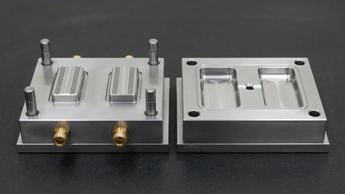
In high-performance product commercialization, the injection mold is the single most critical capital asset. It directly dictates piece-part dimensional repeatability, cosmetic consistency, cycle time efficiency, and per-part unit economics over multi-million-cycle production runs. Precision mold manufacturing transcends basic CNC machining; it represents an interdisciplinary integration of metallurgical heat treatment, precision multi-axis machining, non-traditional electro-discharge physics, thermodynamic heat transfer, and precision mold fitting. Whether engineering rapid pre-hardened bridge tooling for market launch or building multi-cavity Class 101 production molds, adherence to rigorous mold engineering disciplines separates high-yield manufacturing from catastrophic downtime.
- 1. The Anatomy of High-Precision Injection Molds
- 2. Tool Steel Selection & Metallurgy Matrix
- 3. High-Speed Hard Milling (HSM) vs Sinker EDM Spark Erosion
- 4. Mold Thermal Dynamics & Conformal Cooling Optimization
- 5. Parting Line Shut-Offs, Micro-Venting & Flash Elimination
- 6. Mold Surface Finishing & Texturing Standards
- 7. Tooling Metrology, Zeiss CMM Probing & Scientific T1 Trials
- 8. Mold Shop Troubleshooting & Tooling Maintenance Protocol
- 9. Technical Engineering FAQ
1. The Anatomy of High-Precision Injection Molds
Modern injection molds are sophisticated mechanical systems operating under immense dynamic pressures, severe thermal cycles, and tight reciprocating motions. During each molding cycle, the mold structure must withstand clamping forces ranging from 50 to over 1,500 metric tons, while containment internal cavity pressures routinely surge between 300 and 1,200 bar (4,350 to 17,400 psi). A standard high-precision mold assembly comprises several mission-critical subsystems working in exact mechanical registration:
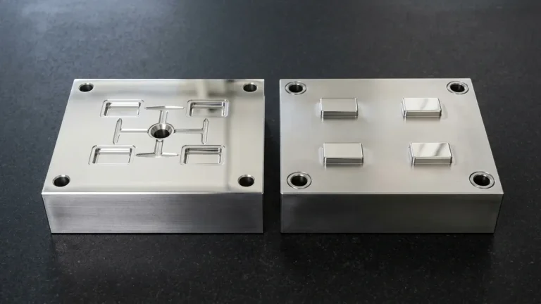
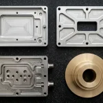
- Core and Cavity Inserts (A-Plate & B-Plate): The primary tooling blocks that define the external and internal part geometry. In precision manufacturing, inserts are nested within hardened pocket recesses in the mold base rather than cut directly into large plates, allowing targeted tool steel selection, localized replacement, and micro-shimming during mold tuning.
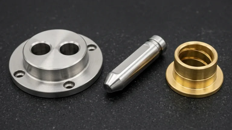
- Mechanical Guiding & Alignment Systems: To prevent core-cavity mismatch caused by thermal expansion or clamping deflection, molds utilize four-corner case-hardened guide pins mated with self-lubricating bronze-graphite bushings. In high-precision micro-molding or deep-draw components, secondary zero-clearance tapered interlocks (side locks and top locks) are ground into the insert peripheries to guarantee alignment within ±0.005 mm (±0.0002 in).
- Actuation Mechanisms (Slides & Lifters): Features with external or internal undercuts that cannot be demolded via straight line of draw require mechanical side actions. Angled horn pins (heel pins) drive hardened slide blocks during mold opening, supported by heavy-duty wedge locking blocks that absorb the direct hydrostatic pressure of the molten plastic during the injection phase. Internal undercuts are released using floating angle lifters fitted with hardened wear plates and anti-rotation guides.
- Ejection & Return System: A precision-ground ejector plate assembly driven by hydraulic machine knockouts or internal pneumatic cylinders. It carries through-hardened or nitrided cylindrical ejector pins, blade ejectors for thin structural ribs, sleeve ejectors for circular bosses, and stripper rings for uniform circumference ejection. Guided ejection pins ensure that the ejector plate maintains strict parallelism with the B-plate throughout its stroke, preventing pin galling and catastrophic tool seizure.
- Melt Delivery System (Feed System): Consists of the sprue bushing, runner network, and gates. Molds utilize balanced cold runner systems with trapezoidal or parabolic cross-sections, or advanced valve-gated hot runner manifolds that eliminate runner scrap, optimize melt pressure delivery, and enable individual cavity gate timing control.
2. Tool Steel Selection & Metallurgy Matrix
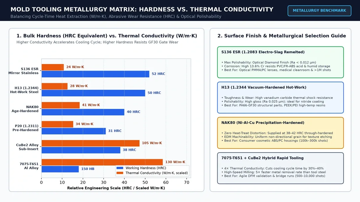
The operational lifespan, cycle time capability, and surface polishability of an injection mold are fundamentally governed by the metallurgy of the tool steel. Selecting the optimal alloy requires balancing wear resistance, impact toughness, corrosion resistance, thermal conductivity, and machinability across different resin chemistries:
1. S136 / Stavax ESR Martensitic Stainless Steel
Electroslag Remelted (ESR) martensitic stainless steel (AISI 420 modified, DIN 1.2083) is the premier tool steel for precision optical, medical, and cosmetic injection molds. The ESR refining process purifies the steel, minimizing non-metallic inclusions, carbide segregation, and micro-porosity. Through-hardened to 48–52 HRC via vacuum heat treatment followed by sub-zero cryogenic stabilization, S136 provides:
- Extreme Polishability: Uniform micro-carbide distribution allows polishing up to optical SPI A-1 and SPI A-0 diamond buff standards without orange peel, pitting, or micro-haze.
- Superior Corrosion Resistance: High chromium content (∼13.6% Cr) protects the mold cavities and internal water cooling channels against corrosive acidic condensates released by flame retardants, PVC resins, fluoropolymers (PVDF, PTFE blends), and humid shop environments.
2. Premium AISI H13 (DIN 1.2344 / JIS SKD61)
H13 is a 5% chromium hot-work tool steel renowned for extreme impact toughness, deep through-hardenability, and resistance to thermal fatigue micro-cracking (heat checking). Vacuum through-hardened and triple-tempered to 46–50 HRC, H13 possesses high yield strength at elevated mold temperatures, making it the industry standard for high-tonnage structural housings, automotive interior and under-hood components, and abrasive mineral- or glass-fiber reinforced polymers (e.g., PA66-GF30, PBT-GF20).
3. NAK80 & P20 Pre-Hardened Tool Steels
Pre-hardened tool steels are supplied in their fully heat-treated condition, eliminating the risks of post-machining volumetric shrinkage, quench distortion, or decarburization. Standard AISI P20 (DIN 1.2311) is delivered at 28–32 HRC, offering economical machinability for medium-volume production tools (up to 250,000 cycles). In contrast, NAK80 is a proprietary precipitation-hardened Ni-Al-Cu alloy steel delivered at 38–42 HRC.
Because its hardness is derived from intermetallic phase precipitation rather than carbon martensite, NAK80 exhibits exceptionally uniform micro-hardness across large cross-sections, machines with minimal burr formation, takes an SPI A-2 diamond polish with zero pinhole risk, and provides the gold standard for rapid bridge tooling runs of 10,000 to 100,000 parts.
4. Aircraft-Grade 7075-T651 Aluminum for Rapid Bridge Tooling
For low-volume production, market-entry pilot validation (1,000 to 10,000 shots), or accelerated bridge production, high-strength forged 7075-T651 aluminum delivers extraordinary tooling advantages. With a thermal conductivity of 130 W/(m·K)—more than four times higher than conventional tool steels (25–30 W/(m·K))—7075 aluminum mold inserts extract heat from the polymer melt dramatically faster, cutting cooling cycle times by 30% to 50%. Furthermore, CNC milling and EDM cutting speeds in aluminum are 3 to 5 times faster than in hardened steel, allowing AS Prototypes to complete rapid prototype tooling within 18 to 25 business days.
| Tool Steel Grade | Delivery Hardness | Thermal Conduct. W/(m·K) | Wear Resistance | Max SPI Polish | Rated Mold Life (Cycles) | Primary Application Target |
|---|---|---|---|---|---|---|
| S136 / Stavax ESR | Annealed (Harden to 48–52 HRC) | 20 W/(m·K) | Very High | SPI A-1 / A-0 | 1,000,000+ | Optical lenses, medical disposables, corrosive resins (PVC, fluoropolymers) |
| AISI H13 (1.2344) | Annealed (Harden to 46–50 HRC) | 28.6 W/(m·K) | High (Toughness focus) | SPI A-2 | 1,000,000+ | Automotive structural parts, glass-filled engineering resins, high-tonnage tools |
| NAK80 | Pre-hardened 38–42 HRC | 41 W/(m·K) | Medium-High | SPI A-2 | 100,000 to 500,000 | Rapid bridge tooling, consumer electronics, cosmetic enclosures with minimal distortion |
| AISI P20 (1.2311) | Pre-hardened 28–32 HRC | 29 W/(m·K) | Moderate | SPI B-1 / B-2 | 50,000 to 250,000 | Large automotive fascias, low-wear commodities (PP, PE, PS), mold base plates |
| 7075-T651 Aluminum | T651 Temper (150 HB) | 130 W/(m·K) | Low (Non-abrasive only) | SPI A-2 / B-1 | 1,000 to 15,000 | Fast prototype verification, rapid tooling, pilot market runs with ultra-short cycles |
3. High-Speed Hard Milling (HSM) vs Sinker EDM Spark Erosion
Modern mold making relies on two complementary subtractive processes to machine complex three-dimensional cores and cavities into hardened tool steel: High-Speed Hard Milling (HSM) and Sinker Electrical Discharge Machining (EDM).
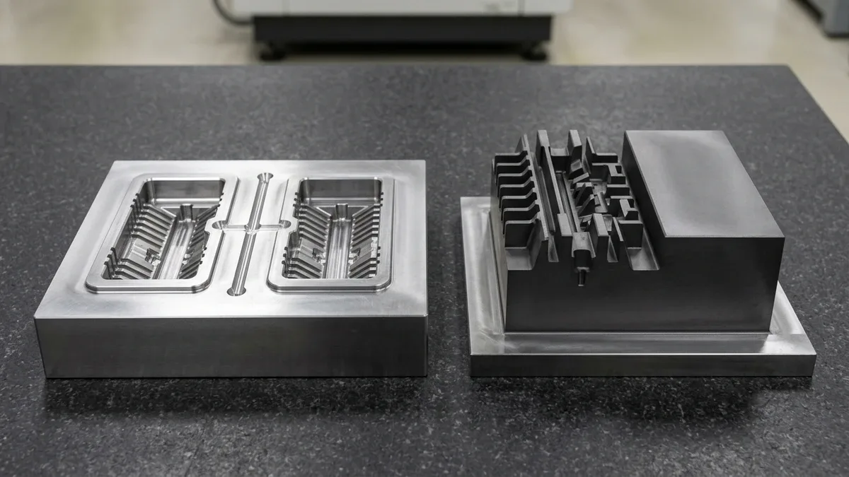
High-Speed Hard Milling (HSM) of Hardened Tool Steels
Rather than machining tool steel in an annealed state and risking distortion during vacuum hardening, high-speed machining centers cut steels directly in their fully hardened state (48–54 HRC). HSM operates on the principles of small radial depths of cut (ae), high cutting speeds (Vc = 150–300 m/min), and high spindle rotation speeds (24,000 to 40,000 RPM) utilizing HSK-E40 toolholding with tight dynamic concentricity.
By employing micro-grain solid carbide ball end mills with nanocomposite TiAlSiN or AlCrN physical vapor deposition (PVD) coatings, HSM drives the heat of deformation into the micro-chips rather than the workpiece. Fine-stepover finishing passes achieve surface finishes as fine as Ra 0.15 to 0.25 μm directly off the CNC spindle. This reduces manual benching and polishing labor by more than 70% while guaranteeing exact geometric compliance to the 3D CAD master model.
Sinker Electrical Discharge Machining (EDM)
Despite the power of HSM, physical rotary cutting tools cannot machine sharp internal inside corners (R < 0.10 mm), deep narrow structural ribs (depth-to-width ratios exceeding 10:1), or intricate texture patterns. Sinker EDM overcomes these mechanical constraints via controlled electrical spark erosion across a deionized hydrocarbon dielectric fluid gap (15 to 40 μm). Each electrical discharge melts and vaporizes microscopic volumes of the tool steel, which are instantly flushed away by pressurized dielectric oil.
The total discharge energy per spark pulse is governed by the discharge voltage ue(t) and current ie(t) over the pulse duration te:
We = ∫0te ue(t) · ie(t) dt
To maximize precision and eliminate thermal surface micro-cracking (the recast or “white layer”), AS Prototypes utilizes ultra-fine-grain isostatically pressed graphite electrodes (particle size ≤ 4 μm, Poco EDM-3 or Tokai HK-6) machined on dedicated graphite HSM centers. Sinker EDM finishes proceed through roughing, semi-finishing, and multi-step planetary orbiting micro-finishing stages, reaching surface textures from VDI 3400 Scale 30 down to VDI 12 (Ra 0.40 μm), directly ready for final diamond micro-polishing.
Wire Electrical Discharge Machining (WEDM)
For precision through-geometry, such as slide guide tracks, core pin pockets, and ejector pin through-holes, submerged 4-axis Wire EDM employs a continuously travelling brass or zinc-coated copper wire (diameter ∅0.20 to ∅0.25 mm) submerged in chilled, deionized water. Submerged WEDM delivers absolute verticality and positioning tolerances of ±0.005 mm (±0.0002 in) with corner radii as tight as R 0.12 mm, ensuring zero-play assembly fits between sliding components.
4. Mold Thermal Dynamics & Conformal Cooling Optimization
In plastic injection molding, cooling represents between 65% and 80% of the total cycle time. The rate and uniformity of heat extraction directly govern part crystallinity, residual stress levels, sink mark formation, and differential shrinkage warpage. Heat transfer across the steel mold boundary follows Fourier’s fundamental law of heat conduction:
q = –k · ∇T
where q is the conductive heat flux (W/m²), k is the thermal conductivity of the tool steel (W/(m·K)), and ∇T is the temperature gradient between the hot plastic melt and the chilled cooling water channel. For a flat molded part with uniform nominal wall thickness h, the theoretical cooling time tc required for the center plane of the wall to reach safe ejection temperature is mathematically expressed by the 1D transient heat conduction equation:
tc = [ h² / (π² · α) ] · ln[ (4 / π) · ( (Tm – Tw) / (Te – Tw) ) ]
In this relationship:
- h: Nominal wall thickness of the plastic component (mm). Notice that cooling time scales quadratically (h²)—doubling wall thickness quadruples cooling time.
- α: Thermal diffusivity of the polymer melt (α = kp / (ρ · Cp), mm²/s), reflecting how fast heat diffuses through the plastic.
- Tm: Polymer melt injection temperature (°C).
- Tw: Mold cooling channel wall temperature (°C).
- Te: Part ejection temperature (°C), at which the resin has solidified sufficiently to resist ejector pin penetration without distortion.
Traditional Drilled Cooling vs Conformal 3D Cooling
Traditional mold cooling relies on straight gun-drilled cooling lines connected with baffles, bubblers, and jumper hoses. While cost-effective, straight drilled lines cannot maintain uniform distance from complex freeform 3D curves, leaving isolated thick sections and deep core bosses undercooled, which leads to localized sink marks and severe post-ejection part warpage.
To solve this thermal bottleneck in high-precision parts, AS Prototypes incorporates Conformal Cooling Channels manufactured via Direct Metal Laser Sintering (DMLS / SLM) in high-strength maraging tool steel (1.2709). Conformal channels curve smoothly in three dimensions, maintaining a constant 2.5 to 3.5 mm offset from the molding surface. By maintaining turbulent coolant flow (Reynolds number Re > 4,000) throughout the circuit, conformal cooling extracts heat uniformly, reduces total injection cycle times by 25% to 45%, and virtually eliminates asymmetric thermal warpage.
5. Parting Line Shut-Offs, Micro-Venting & Flash Elimination
Flash—the unintended seepage of molten polymer into clearance gaps between parting surfaces—ruins cosmetic quality, interferes with downstream assembly, and increases piece-part trimming labor. Flash occurs when internal cavity pressure forces mold plates apart or when parting line shut-offs lack sufficient contact pressure.
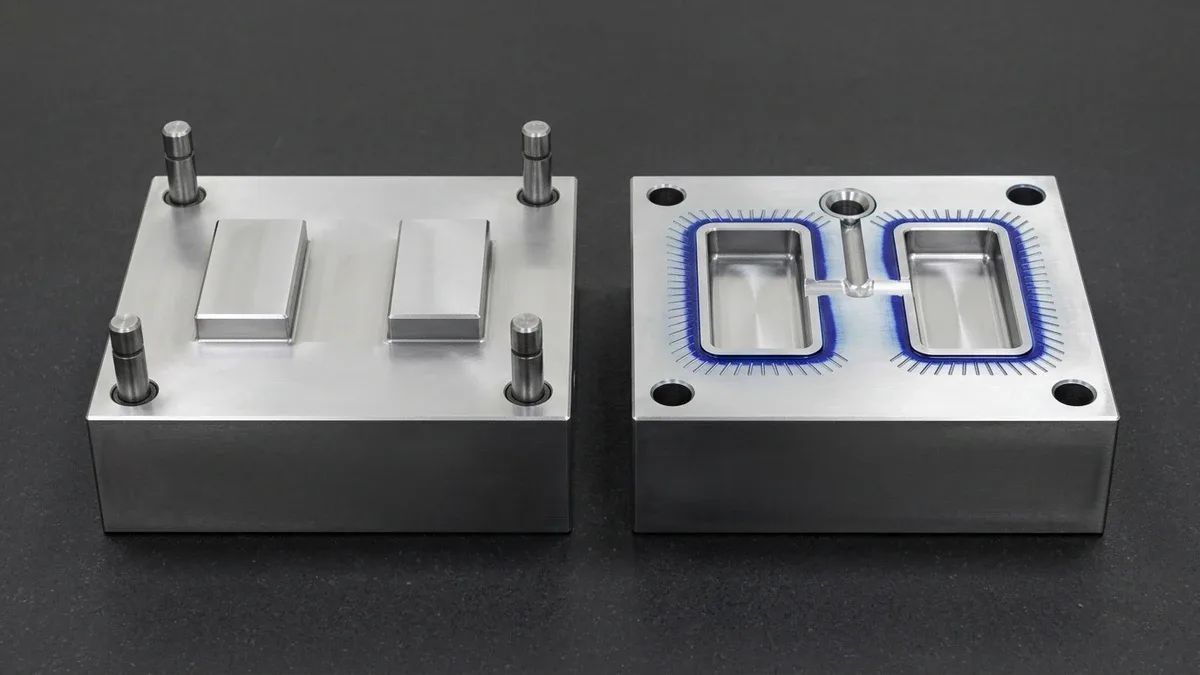
Parting Line Shut-Off Engineering
To ensure absolute zero-flash sealing across hundreds of thousands of clamp cycles, AS Prototypes executes a multi-step shut-off strategy:
- Shut-Off Draft Angles: Sliding shut-offs between core and cavity blocks must maintain a minimum draft angle of 5° to 7° (never vertical 0°). A steep draft ensures that mating faces disengage immediately upon mold opening, completely eliminating surface galling, scoring, and wear.
- Parting Land Relief: Rather than attempting to maintain precision contact across the entire mold plate surface (which dissipates clamping tonnage), we machine primary shut-off lands with a narrow width of 15 to 25 mm around the cavity perimeter. The remaining surface area is relieved by 0.50 to 1.0 mm, concentrating the injection molding machine’s full clamping tonnage precisely where molten plastic containment is required.
- Prussian Blue Spotting & Pre-Load: Mold makers perform extensive manual spotting using Prussian blue paste on precision spotting presses. Parting lands are ground and hand-stoned to achieve greater than 85% uniform contact area, with an engineered 0.02 mm (0.0008 in) crush pre-load ground into critical core-cavity shut-offs to compensate for dynamic machine platen deflection under full tonnage.
Scientific Micro-Venting Specifications
As molten plastic rushes into the mold cavity at speeds up to 300 mm/s, trapped air and polymer outgassing must evacuate instantaneously. Inadequate venting causes diesel burns (combustion of trapped volatile gases under adiabatic compression), short shots, and weak weld lines. The depth of the primary vent land must be calibrated precisely to the viscosity of the specific polymer at molding temperature:
- Low-Viscosity Crystalline Resins (PA66, POM, PBT): Vent depth must not exceed 0.010 to 0.015 mm (0.0004 to 0.0006 in) to prevent resin flash into the vent.
- Medium-Viscosity Resins (ABS, PP, PE, HIPS): Vent depth is calibrated to 0.020 to 0.030 mm (0.0008 to 0.0012 in).
- High-Viscosity Resins (PC, PMMA, Polysulfone, PEEK): Vent depth is sized to 0.035 to 0.050 mm (0.0014 to 0.0020 in).
The primary vent land extends for a short distance of 1.0 to 1.5 mm, immediately opening into a secondary atmospheric relief channel 0.8 to 1.2 mm deep that vents freely out the perimeter of the mold base.
6. Mold Surface Finishing & Texturing Standards
The cavity surface texture dictates the cosmetic appearance, tactile feel, light reflection, and mold release characteristics of the molded plastic component. Mold surface preparation follows international Society of the Plastics Industry (SPI) standards, chemical photo-etching, and EDM texture scales:
SPI Mold Finish Classifications
- SPI Class A (Diamond Buff Mirror Finish): Prepared using rotary felt bobs and progressively finer diamond paste compounds. SPI A-1 utilizes 3 μm diamond paste (roughness Ra 0.012 to 0.025 μm) for optical lenses, light guides, and high-gloss transparent acrylic (PMMA) parts. SPI A-2 (6 μm diamond, Ra 0.025 to 0.05 μm) and SPI A-3 (15 μm diamond, Ra 0.05 to 0.10 μm) are selected for premium cosmetic enclosures.
- SPI Class B (Grit Sandpaper Semi-Gloss Finish): Hand-finished using silicon carbide abrasive papers lubricated with light honing oil. Grits range from 600-grit (SPI B-1, Ra 0.05 to 0.10 μm) to 320-grit (SPI B-3, Ra 0.15 to 0.30 μm), providing a clean satin luster that masks microscopic flow lines.
- SPI Class C (Grit Stone Matte Finish): Finished with aluminum oxide polishing stones ranging from 600-grit (SPI C-1, Ra 0.15 to 0.30 μm) down to 320-grit (SPI C-3, Ra 0.60 to 1.0 μm), popular for non-cosmetic interior ribs, chassis bases, and industrial enclosures.
- SPI Class D (Dry Blast Textured Finish): Produced by dry blasting cavity surfaces with pressurized glass beads (SPI D-1, Ra 0.40 to 0.80 μm) or aluminum oxide media (SPI D-2 and D-3, Ra 1.0 to 3.5 μm), producing a non-directional matte texture that hides sink marks and scratches.
| SPI Finish Class | Polishing Method / Abrasive | Surface Roughness (Ra) | Visual & Optical Effect | Min. Draft Required | Typical Application |
|---|---|---|---|---|---|
| SPI A-1 | Grade 3 Diamond Buff Compound | 0.012 – 0.025 μm | Optically pure mirror gloss | 1.0° | Automotive lenses, light pipes, medical cuvettes, clear PMMA/PC |
| SPI A-2 | Grade 6 Diamond Buff Compound | 0.025 – 0.050 μm | High gloss reflective luster | 1.0° | Consumer electronics top covers, cosmetic enclosures and housings |
| SPI B-1 | 600 Grit Silicon Carbide Paper | 0.050 – 0.100 μm | Fine satin semi-gloss | 1.0° | Appliance panels, hand-held device bezels, non-glare displays |
| SPI C-1 | 600 Grit Aluminum Oxide Stone | 0.150 – 0.300 μm | Low-sheen uniform matte | 1.5° | Internal chassis, structural brackets, non-cosmetic subassemblies |
| SPI D-1 | Dry Blast #11 Glass Beads | 0.400 – 0.800 μm | Velvet textured satin matte | 2.0° | Industrial tool handles, automotive trim, fingerprint-resistant cases |
Draft Angle Multiplier for Textured Cavities
When applying Mold-Tech (MT) acid-etched textures, laser texturing, or VDI 3400 EDM spark finishes to deep cavity sidewalls, parts will drag and scuff during mold opening unless draft angles are scaled proportionally. The fundamental toolmaker rule of thumb dictates:
Rule of Thumb: Provide 1.0° to 1.5° of draft for every 0.025 mm (0.001 in) of texture depth.
For example, a standard Mold-Tech MT-11010 stipple texture with a nominal depth of 0.025 mm requires a minimum of 2.5° to 3.0° of draft. Heavy leather grains or geometric knurls with depths of 0.075 mm require at least 5.0° to 6.0° of draft to ensure clean part release without ejection scuffing.
7. Tooling Metrology, Zeiss CMM Probing & Scientific T1 Trials
The validation of a precision injection mold follows a rigorous closed-loop metrology and scientific molding protocol before customer shipment or production sign-off.
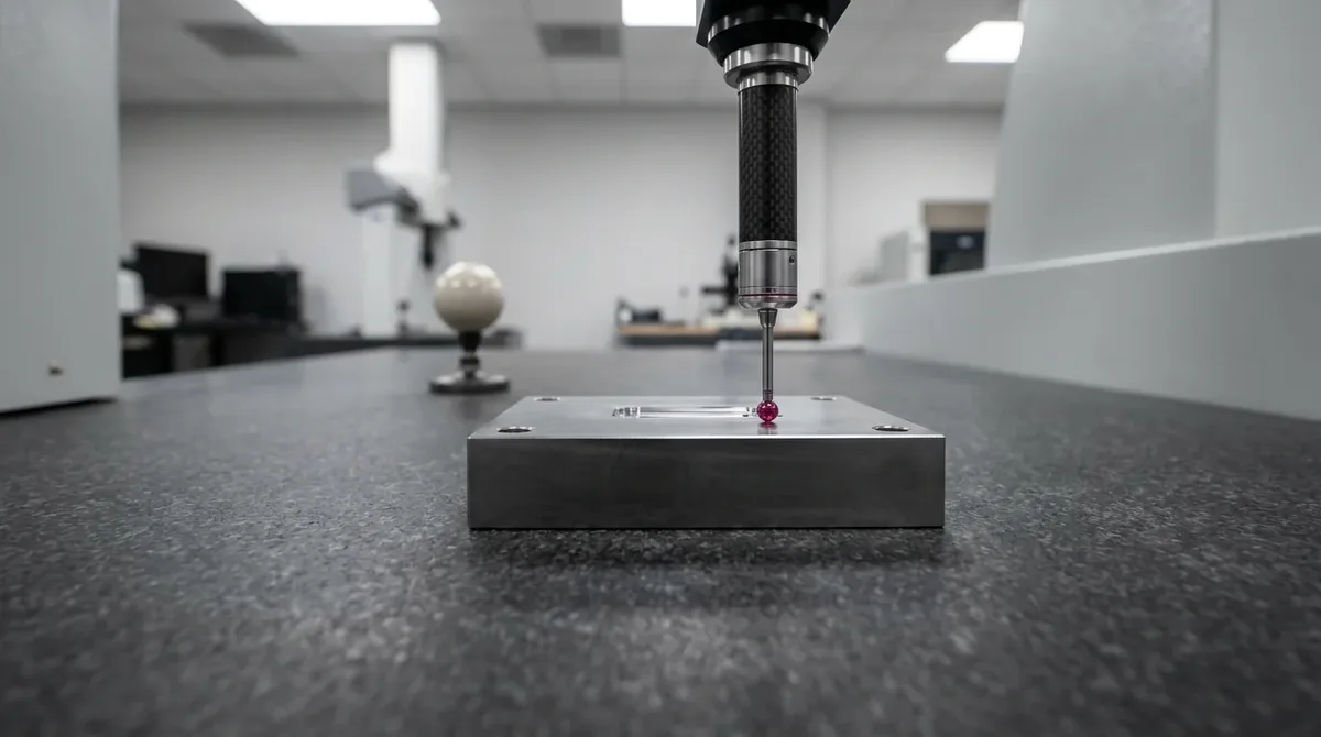
Electrode & Hardened Cavity Metrology
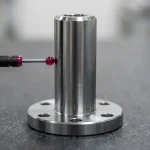
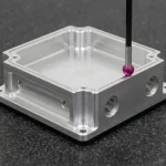
Prior to spark erosion, all graphite and copper electrodes are probed on our Zeiss Coordinate Measuring Machines (CMM) to verify sparking offsets, spark gap clearance, and electrode dimensional accuracy within ±0.005 mm. Following CNC hard milling, WEDM, and EDM spark erosion, the finished core and cavity blocks are aligned on their master ground Datum A, B, and C reference faces on the CMM inspection plate. Touch-trigger ruby probes and 2.5D optical vision measurement verify true position, cavity profile tolerance, and slider shut-off coordinates against the 3D CAD engineering step file.
Scientific Injection Molding T1 Trial Protocol
Once mold assembly is complete, initial T1 sampling takes place on our electric and servo-hydraulic injection molding machines (ranging from 50 to 450 tons). Rather than arbitrary technician adjustments, AS Prototypes utilizes decoupled scientific molding principles:
- Rheological Viscosity Curve Study: Injecting short shots at progressively higher injection speeds (fill times from 0.5 s to 4.0 s) to measure effective polymer melt viscosity versus shear rate. We identify the stable flat plateau of the viscosity curve to operate in an injection velocity window where resin viscosity is insensitive to minor temperature or lot-to-lot resin variations.
- Multi-Cavity Balance Test: Filling multi-cavity molds to 95% full without pack pressure to verify filling balance across all gates. High-precision tooling requires greater than 95% shot balance between the fastest and slowest filling cavities to prevent flash on one part while shorting another.
- Gate Freeze (Gate Seal) Study: Weighing molded parts across incremental holding pressure times (from 1 second up to 15 seconds). The exact point where part mass plateaus indicates that the gate has frozen solid, establishing the precise pack-and-hold time needed to avoid sink marks while preventing over-packing stress.
- First Article Inspection (FAI): Comprehensive dimensional layout inspection across T1 molded sample parts using 2.5D optical vision measuring systems and Zeiss CMM probing (available upon request for critical dimensional verification) to verify shrinkage compensation, GD&T compliance, and assembly snap-fits.
8. Mold Shop Troubleshooting & Tooling Maintenance Protocol
Even perfectly designed molds encounter shop floor anomalies due to resin degradation, machine platen deflection, or cooling line fouling. The following matrix illustrates AS Prototypes’ root-cause diagnosis and tooling corrective actions:
| Molding Defect | Shop-Floor Symptom | Tooling / Process Root Cause | Engineered Mold Shop Corrective Action |
|---|---|---|---|
| Parting Line Flash | Thin polymer film protruding along mold separation line | Insufficient clamp tonnage, worn shut-off land, lack of shut-off pre-load, machine platen bowing | Re-spot parting lands to >85% blue contact; grind 0.02 mm pre-load crush into parting land perimeter; relieve non-sealing plate areas |
| Sink Marks & Voids | Cosmetic depressions above thick internal ribs or bosses | Localized volumetric shrinkage; rib base thickness exceeds 60% of nominal wall; premature gate freeze | Core out thick sections to nominal wall × 0.60; enlarge gate cross-section to prolong pack pressure transmission; add conformal cooling |
| Diesel Burn Marks | Black or brown charred spots at the end-of-fill path | Trapped atmospheric air compressed adiabatically by melt front, reaching auto-ignition temperature | Add precision micro-vents (0.015–0.030 mm deep); install porous metal vent inserts or vacuum mold evacuation; relocate gate |
| Ejector Pin Stress Marks | White stress discoloration or dimpling on part B-side | Excessive ejection force required; vacuum lock on deep cores; undersized ejector pin surface area; insufficient draft | Increase draft angles by 0.5°–1.0°; install air poppet valves in deep cores to break vacuum; enlarge ejector pin diameters or add stripper plates |
| Dimensional Warpage | Part bows, twists, or departs from drawing flatness | Asymmetric thermal cooling between core and cavity halves; differential shrinkage due to molecular orientation | Re-balance cooling circuits; adjust separate water zone temperatures (cooler cavity / warmer core); optimize gate position to balance flow vectors |
Preventive Tooling Maintenance (PM) Lifecycle
To preserve mold asset value and maintain zero-defect output across high-volume production, AS Prototypes executes a standardized three-tiered preventive maintenance schedule:
- Level 1 Maintenance (Every 20,000 Cycles): Mold remains in the injection press or is transferred to a bench. Parting surfaces, slide tracks, and vents are cleaned using ultrasonic degreasers. Guide pins and ejector assemblies are inspected for scoring and relubricated with high-temperature food-grade synthetic grease.
- Level 2 Maintenance (Every 100,000 Cycles): Core and cavity inserts are pulled from the mold base. All water cooling lines are chemically descaled and pressure-tested at 10 bar to detect O-ring seal leaks. Slides, horn pins, and angle lifters are disassembled, micrometer-measured for wear, and re-spot checked. Vents are cleaned of burnt polymer residue.
- Level 3 Comprehensive Overhaul (Every 500,000 Cycles): Complete tool teardown. Cavities undergo laser micro-welding or re-EDM spark erosion to restore worn shut-offs. Guide bushings, ejector pins, and return springs are replaced with standard catalog components. Mold cavities are re-polished to original SPI specifications and re-validated through First Article Inspection (FAI).
9. Technical Engineering FAQ
For abrasive glass-filled resins (such as PA66-GF30 or PBT-GF30), through-hardened AISI H13 (48–50 HRC) or DC53 / D2 tool steel (58–60 HRC) is strongly recommended for high-wear areas such as gates, runners, and core shut-offs. For maximum production longevity exceeding 1,000,000 cycles, tool inserts are often treated with Physical Vapor Deposition (PVD) titanium aluminum nitride (TiAlN) or diamond-like carbon (DLC) coatings to prevent abrasive gate wash.
High-Speed Hard Milling (HSM) is faster and more cost-effective for open contoured 3D surfaces, large pockets, and complex parting surfaces, cutting hardened steel up to 54 HRC with Ra 0.2 μm finishes. Sinker EDM is essential for features that rotary cutting tools cannot physically machine, including sharp inside corners (R < 0.05 mm), deep narrow structural ribs with draft angles under 0.5°, and standardized VDI spark erosion cosmetic textures.
Factory production turnaround for rapid bridge tooling and validated T1 molded sample parts strictly ranges from 18 to 35 business days. This timeframe encompasses complete DFM engineering review, mold flow analysis, tool steel procurement, CNC roughing, vacuum heat treatment, HSM finishing, wire and sinker EDM, hand fitting, and scientific molding press trials. Complex Class 101 production tools with multi-axis hydraulic slides or hot runner systems require 18 to 35 business days.
Zero-flash shut-offs are achieved by machining primary shut-off lands with 5° to 7° draft angles and relieving non-critical plate areas. Toolmakers perform meticulous Prussian blue paste spotting on spotting presses, hand-stoning mating lands to achieve >85% surface contact with an engineered 0.02 mm (0.0008 in) crush pre-load. Furthermore, micro-vents are precisely depth-calibrated (0.010 mm to 0.035 mm depending on resin viscosity) to vent air without permitting polymer flash.
Yes. AS Prototypes regularly manufactures injection molds according to North American (DME) and European (HASCO, Meusburger, MISUMI) standards. We incorporate standard off-the-shelf guide pins, bushings, ejectors, slide retainers, and hot runner systems (Yudo, Mold-Masters, Synventive), enabling seamless maintenance, spare parts replacement, and global interchangeability at your local molding facility.
Transition Seamlessly from Rapid Tooling to High-Precision Molding
Optimize cavity life, gate geometry, and part unit economics with our in-house tooling and injection molding engineering team. Upload your 3D CAD models (STEP/IGES) for a comprehensive Moldflow and DFM manufacturability assessment.
Upload 3D CAD for Tooling & Molding DFM Review