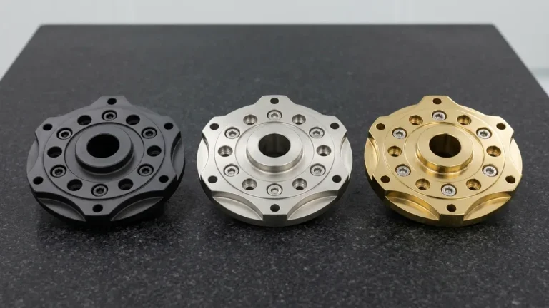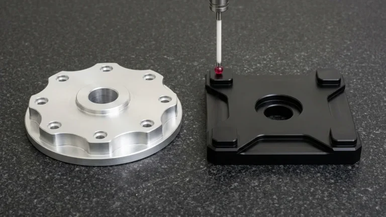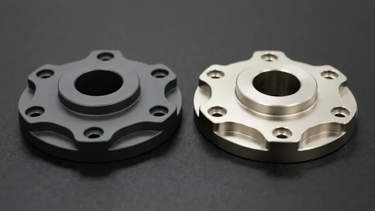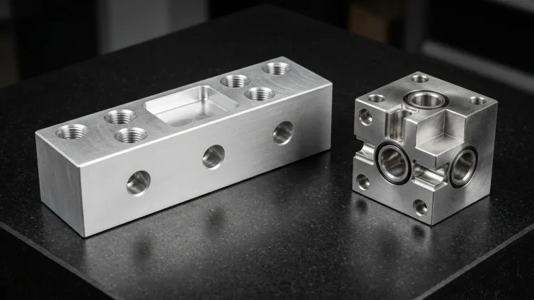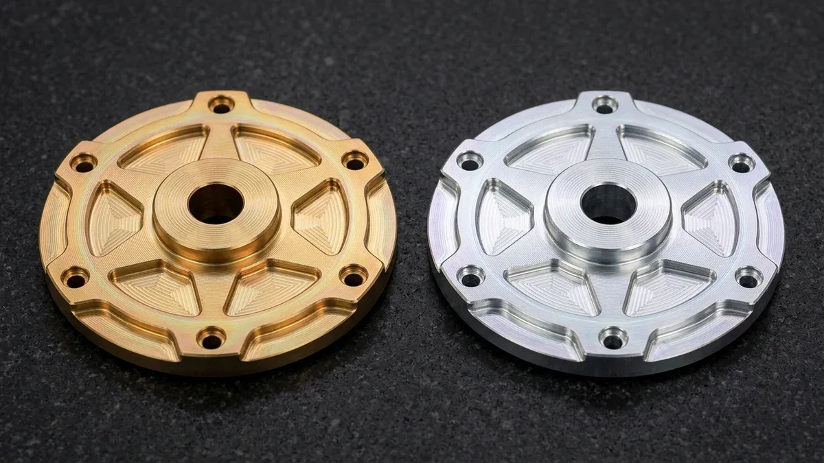
Specifying chromate conversion coating—widely known as chem film, Alodine, or SurTec 650—is the gold-standard passivation method for aluminum alloys requiring atmospheric corrosion defense and low electrical contact impedance. Through a chemical redox reaction, it converts active aluminum into a nanometer-to-micrometer passive film measuring 0.25 to 1.5 µm (0.00001″ to 0.00006″ / 10 to 60 µin) thick.
Unlike anodic oxidation, which grows a thick dielectric ceramic barrier that insulates surfaces and alters thread pitch diameters, chemical conversion coatings preserve raw metallic conductivity and dimensional accuracy. Under MIL-DTL-5541F and ASTM B449 governance, properly processed aluminum substrates withstand 168 to 336 hours of ASTM B117 neutral salt spray while maintaining contact resistance below 5,000 µΩ/in² (775 µΩ/cm²).
At our Shenzhen CNC machining and surface finishing facility, we execute both legacy Type I hexavalent and RoHS-compliant Type II trivalent conversion processes across 6061-T6, 7075-T651, and 5052-H32 hardware. This engineering guide details MIL-DTL-5541F classifications, quantitative electrical contact resistance modeling, thermal dehydration limits, 4-step immersion bath controls, and selective dual-finish masking DFM guidelines.
Executive Summary & Engineering Takeaways (BLUF)
- Type I vs. Type II Regulatory Split (MIL-DTL-5541F): Type I hexavalent chromium (Cr6+, Alodine 1200S) delivers active self-healing corrosion inhibition for defense exemptions, whereas Type II trivalent chromium (Cr3+ TCP / SurTec 650) achieves full RoHS, REACH, and ELV compliance with clear-to-iridescent metallic passivity.
- Class 1A vs. Class 3 Functional Trade-Off: Class 1A deposits a heavier 0.43–2.0 g/m² (40–185 mg/ft², meeting MIL-DTL-81706B §3.5.3 ≥ 40 mg/ft²) film for 168–336 hours of ASTM B117 salt-fog survival and paint adhesion; Class 3 deposits a thinner 0.11–0.43 g/m² (10–40 mg/ft²) film keeping electrical contact resistance ≤ 5,000 µΩ/in² before salt spray and ≤ 10,000 µΩ/in² after 168 hours.
- Zero Dimensional Compensation on Tight CNC Features: Because total film thickness spans only 0.25–1.5 µm (0.00001″–0.00006″), precision CNC features held to ±0.010 mm to ±0.020 mm (±0.0004″ to ±0.0008″)—including ISO H7 bearing bores and fine internal threads—require zero pre-machining stock offset.
- Critical 60°C (140°F) Thermal Dehydration Ceiling: Wet-formed hexavalent Cr6+ hydrogel films must never be force-dried or baked above 60°C (140°F) per ASTM B449, as dehydration fractures the amorphous Cr2O3·xH2O gel; specify trivalent zirconium-chromium Type II coatings (heat resistant to 100°C–150°C unpainted) when subsequent powder-coating cure ovens reach 180°C–200°C (356°F–392°F) on 5052-H32 or 6061-T6 (never 7075-T6).
- Predictable Ex-Factory Finishing Turnaround: Our in-house engineering team delivers bare CNC prototypes in 4–8 business days and conversion-coated or selective dual-finish (anodize plus chem film) assemblies in 7–12 business days ex-factory, prior to 3–5 business days of international express air transit.
Article Engineering Navigation
- 1. Electrochemical Passivation & MIL-DTL-5541F Chemistry
- 2. Class 1A vs. Class 3: Corrosion Defense vs. RF Grounding
- 3. Contact Resistance Modeling & Thermal Dehydration Limits
- 4. Shop-Floor Immersion SOP & Aluminum Alloy Metallurgy
- 5. Tight CNC Tolerances & Selective Anodize Masking DFM
- 6. Defect Troubleshooting & In-House Metrology Verification
- 7. Process Limitations, Trade-Offs & Ex-Factory Lead Times
- 8. Technical Engineering FAQ
1. Electrochemical Passivation Mechanism & MIL-DTL-5541F / ASTM B449 Chemistry
Raw aluminum alloys instantaneously form a thin 2 to 5 nm (0.0000001″ to 0.0000002″) atmospheric oxide skin upon air exposure, but this native film is chemically unstable in chloride-rich or humid environments. Chromate conversion coating replaces this fragile native film through a nonelectrolytic immersion redox reaction governed by international standards MIL-DTL-5541F and ASTM B449.
When a freshly deoxidized aluminum part enters an acidic conversion bath containing fluoride activators (F−) at pH 1.5 to 4.0, hydrofluoric complexes strip the residual aluminum oxide and initiate anodic dissolution of metallic aluminum (Al0 → Al3+ + 3e−). Simultaneously, cathodic reduction of protons at the metal-liquid interface elevates the local interfacial pH.
This localized interfacial alkalinization precipitates an insoluble, amorphous chromium-aluminum hydroxide hydrogel directly onto the alloy lattice. Because the protective layer grows chemically from the substrate rather than depositing via external electrical current, it coats internal waveguides, blind tapped holes, and complex 3-axis and 4-axis milled pockets uniformly without edge build-up.
Type I Hexavalent Chromium (Cr6+ / Alodine 1200S) Chemistry
Under MIL-DTL-5541F Type I specifications, the bath utilizes hexavalent dichromate ions (Cr2O72−) accelerated by ferricyanide and fluoride activators at 20°C to 30°C (68°F to 86°F). Roughly 75% to 85% of the resulting hydrogel matrix consists of insoluble trivalent hydrated chromic oxide (Cr2O3·xH2O) acting as a dense physical barrier.
Crucially, the remaining 15% to 25% of the Type I film retains soluble hexavalent chromate ions (CrO42−) trapped within the hydrated gel network. If a mechanical scratch exposes bare aluminum during field service, ambient moisture leaches these mobile Cr6+ ions into the defect, where they reduce to insoluble Cr3+ and self-heal the breach.
Type II Trivalent Chromium (Cr3+ TCP / SurTec 650 / Alodine 5200) Chemistry
Because hexavalent chromium is restricted under European RoHS (Directive 2011/65/EU < 0.1 wt% Cr6+), REACH SVHC, and EU ELV regulations, the vast majority of commercial hardware produced in our surface finishing lines specifies MIL-DTL-5541F Type II. Type II formulations employ Trivalent Chromium Passivation (TCP), predominantly utilizing hexafluorozirconate (ZrF62−) and trivalent chromium salts.
Operating at pH 3.6 to 4.0 and bath temperatures of 25°C to 40°C (77°F to 104°F), Type II baths co-precipitate a dense zirconium-chromium-aluminum oxide matrix (ZrO2 / Cr2O3 / Al2O3). The resulting finish appears optically clear with a faint bluish-violet or silver interference tint and satisfies QPL-81706 salt-spray benchmarks.
2. Class 1A vs. Class 3: Corrosion Defense vs. RF/EMI Grounding
Beyond selecting Type I or Type II chemistry, mechanical and electrical engineers must explicitly call out the functional Class on the 2D engineering drawing. MIL-DTL-5541F defines two operational classes—Class 1A and Class 3—that govern immersion dwell time, coating mass per unit area, salt-spray survival, and interfacial electrical resistance across precision surface finishing workflows.
MIL-DTL-5541F Class 1A: Maximum Barrier Protection & Organic Paint Primer
Class 1A is engineered for maximum unpainted corrosion resistance and superior organic coating adhesion. Using 1 to 3 minute (60–180 s) immersion dwell times, the bath builds a thicker film with a coating weight of 0.43 to 2.0 g/m² (40–185 mg/ft², above the MIL-DTL-81706B §3.5.3 ≥ 40 mg/ft² minimum) and thickness of 0.50 to 1.50 µm (0.00002″ to 0.00006″).
In Type I chemistry, this heavier film displays a deep iridescent golden-yellow to rich amber-brown appearance, whereas Type II Class 1A exhibits a distinct iridescent blue-violet sheen. Unpainted Class 1A test panels must endure at least 168 hours—and routinely achieve 336 hours on 6061-T6—of ASTM B117 5% neutral salt spray without white aluminum corrosion pits.
Furthermore, the micro-porous hydrated gel structure of Class 1A acts as a chemical bonding bridge for subsequent epoxy liquid paints or electrostatic powder coatings. Painting directly over raw machined aluminum frequently leads to blistering and delamination under humidity cycling, whereas a Class 1A undercoat locks the polymer primer to the metal substrate.
MIL-DTL-5541F Class 3: Ultra-Low Contact Resistance for RF & Avionics Chassis
In 5G millimeter-wave waveguide cavities, avionics boxes, and PCB grounding bosses, thick barrier coatings impede high-frequency return currents. Class 3 solves this by restricting immersion dwell times to 30 to 90 seconds, yielding a lighter coating weight of 0.11 to 0.43 g/m² (10 to 40 mg/ft²) and thickness of 0.25 to 0.75 µm (0.00001″ to 0.00003″).
Per MIL-DTL-81706 qualification testing under 1.38 MPa (200 psi) electrode contact pressure, Class 3 surfaces must exhibit an electrical contact resistance of ≤ 5,000 µΩ/in² (≤ 775 µΩ/cm²) as-applied. After 168 hours of ASTM B117 neutral salt-fog exposure, post-corrosion contact resistance must remain ≤ 10,000 µΩ/in² (≤ 1,550 µΩ/cm²) to guarantee uninterrupted EMI/RFI shielding continuity.
| Specification Designation | Core Chemistry & RoHS Status | Film Thickness & Coating Weight | Electrical Contact Resistance | ASTM B117 Salt Spray | Recommended Application / When to Choose |
|---|---|---|---|---|---|
| MIL-DTL-5541F Type I, Class 1A | Hexavalent Cr6+ (Alodine 1200S); Non-RoHS (Defense Exemption) | 0.50–1.50 µm (0.02–0.06 mil) 0.43–2.0 g/m² (40–185 mg/ft²; ≥ 40 mg/ft² min) | 5,000–15,000 µΩ/in² (Moderate conductivity) | 168–336+ hrs without white corrosion | Legacy military/aerospace structural brackets, fluid manifolds, and high-adhesion paint primer base |
| MIL-DTL-5541F Type I, Class 3 | Hexavalent Cr6+ (Light Golden-Clear); Non-RoHS | 0.25–0.75 µm (0.01–0.03 mil) 0.11–0.43 g/m² (10–40 mg/ft²) | ≤ 5,000 µΩ/in² initial; ≤ 10,000 µΩ/in² post-168h | ≥ 168 hrs per MIL-DTL-81706 | Defense radar waveguides, avionics EMI gasket lands, and masked grounding pads on anodized housings |
| MIL-DTL-5541F Type II, Class 1A | Trivalent Cr3+ + Zr (SurTec 650 / TCP); 100% RoHS & REACH | 0.40–1.20 µm (0.016–0.047 mil) 0.22–1.0 g/m² (20–95 mg/ft²; ≥ 10 mg/ft² min) | 4,000–10,000 µΩ/in² (Low-to-moderate) | 168–336 hrs neutral salt fog | RoHS commercial automotive mounts, medical frames, and high-temperature powder-coat pre-treatment |
| MIL-DTL-5541F Type II, Class 3 | Trivalent Cr3+ + Zr (Clear Metallic); 100% RoHS & REACH | 0.20–0.60 µm (0.008–0.024 mil) 0.11–0.32 g/m² (10–30 mg/ft²) | ≤ 3,000–5,000 µΩ/in² initial; ≤ 10,000 µΩ/in² post-168h | ≥ 168 hrs neutral salt fog | 5G telecom RF filter cavities, PCB grounding standoffs, and commercial electronic appliance enclosures |
| MIL-A-8625 Type II Anodizing | Electrolytic Sulfuric Acid Al2O3; RoHS Compliant | 8.0–25.0 µm (0.31–1.00 mil) 50% inward / 50% outward growth | Dielectric Insulator (> 1012 Ω·cm; ~200–400 V breakdown) | ≥ 336 hrs (nickel-acetate or hot DI sealed) | Cosmetic structural housings, dyed robotics covers, and exterior consumer hardware requiring scratch resistance |
| MIL-A-8625 Type III Hardcoat | Low-Temp Sulfuric Acid Al2O3 (0°C to 5°C); RoHS Compliant | 25.0–60.0 µm (1.00–2.40 mil) 450–550 HV surface hardness | High-Voltage Dielectric Insulator (1,000–1,500 V breakdown) | ≥ 336–500+ hrs neutral salt spray | High-wear pneumatic cylinders, sliding valve spools, and abrasive actuator guideways |
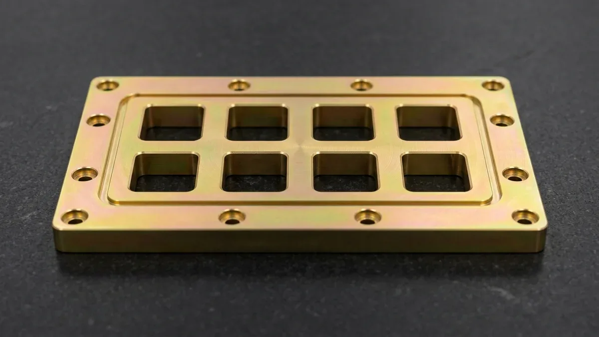
In microwave hardware, the thin-film (0.25–0.75 µm / 10–30 µin) conversion layer preserves machined surface roughness and aperture geometry. As shown on the 3-axis CNC-milled 6061-T6 aluminum waveguide bulkhead plate below, a golden Class 3 coating protects the eight stepped rectangular apertures and continuous perimeter elastomeric gasket groove while preserving the flycut toolpath sheen.
3. Quantitative Electrical Contact Resistance Modeling & Thermal Dehydration Limits
Understanding why a thin-film (0.25–1.0 µm / 10–40 µin) conversion layer maintains high electrical conductivity requires analyzing interfacial contact physics and high-frequency electromagnetic skin depth (δs). When two machined aluminum flanges bolt together or compress against a conductive EMI gasket, current flows across microscopic surface asperities (a-spots) while tunneling through the thin passive film.
Mathematical Derivation of Total Interface Contact Resistance
Following Holm electrical contact theory for bolted EMI/RFI joints and MIL-DTL-81706 qualification electrodes, the total interfacial contact resistance (Rcontact) across a conversion-coated aluminum flange is the sum of the bulk tunnel/film resistance through the conversion layer and the metallic constriction resistance across the load-bearing micro-asperities:
Where Areal = Fclamp ÷ Hsurface = (Papparent × Aapparent) ÷ Hsurface
RF Skin Depth: δs = 1 ÷ √(π × f × µ0 × σ) = √[ρbase ÷ (π × f × µ0 × µr)]
Each physical parameter in our shop-floor electrical bonding and microwave skin-depth equations is defined below with dual metric and imperial engineering units to support direct DFM verification across RF waveguide flanges, chassis ground bosses, and EMI shielding gaskets:
- Rcontact: Total interfacial contact resistance normalized per unit apparent area (µΩ·in² or µΩ·cm²).
- ρfilm: Effective tunnel/conduction electrical resistivity of the compressed chromate or trivalent Zr/Cr conversion hydrogel under 1.38 MPa (200 psi) clamping stress (typically 0.18 to 0.32 Ω·cm / 180 to 320 mΩ·cm in hydrated form).
- tfilm: Conversion coating thickness (0.25–0.75 µm / 0.00001″–0.00003″ for Class 3; 0.50–1.50 µm / 0.00002″–0.00006″ for Class 1A).
- Areal: True load-bearing metallic contact area formed by plastic deformation of machining toolpath peaks under clamping pressure Papparent = 1.38 MPa (200 psi) against aluminum surface Meyer hardness Hsurface ≈ 950 MPa (137.8 ksi).
- ρbase & δs: Bulk electrical resistivity of 6061-T6 aluminum substrate (3.99 × 10⁻⁶ Ω·cm / 1.57 × 10⁻⁶ Ω·in at 20°C / 68°F) and high-frequency RF skin depth δs—measuring 0.82 µm (32 µin) at 10 GHz and 0.49 µm (19 µin) at 28 GHz in pure Al (σ = 3.77 × 10⁷ S/m), or 1.01 µm (40 µin) at 10 GHz and 0.60 µm (24 µin) at 28 GHz in 6061-T6 alloy (σ = 2.50 × 10⁷ S/m).
- n and aspot: Number density of micro-contact spots and mean asperity contact radius (typically aspot ≈ 8–15 µm / 315–590 µin on an Ra 0.8 µm / 32 µin milled datum).
Worked Shop-Floor Engineering Calculation: Consider a 6061-T6 waveguide flange milled to Ra 0.8 µm (32 µin) and tested over 6.45 cm² (1.00 in²) under the standard MIL-DTL-81706 electrode clamping stress of 1.38 MPa (200 psi). Dividing clamping stress by 950 MPa Meyer hardness yields a true contact area Areal = 0.00935 cm² (0.00145 in²).
With 1,200 micro-asperities of mean radius 10 µm (0.001 cm), the metallic constriction term contributes only 1.66 µΩ. For a Class 3 film of thickness 0.40 µm (0.000016″) and hydrated tunnel resistivity 0.22 Ω·cm (220 mΩ·cm), the film resistance is 941.2 µΩ, yielding a total contact resistance of 943 µΩ/in² (146 µΩ/cm²)—well below the 5,000 µΩ/in² threshold.
Conversely, if an engineer specifies a heavier Class 1A coating (1.40 µm / 0.000055″ thick) that has partially dehydrated (effective resistivity rising to 0.45 Ω·cm / 450 mΩ·cm), the film resistance jumps to 6,738 µΩ. That pushes total interfacial contact resistance to 6,740 µΩ/in² (1,045 µΩ/cm²), failing Class 3 RF grounding requirements.
The Critical 60°C (140°F) Thermal Dehydration Rule
A frequent failure mode in aluminum surface finishing occurs during post-rinse drying or thermal assembly. Newly precipitated Type I hexavalent coatings exist as a gelatinous hydrated complex (Cr2O3·xH2O) during the first 24 hours of aging. Bound water molecules keep the hydrogel plastic and let mobile Cr6+ ions diffuse into scratches.
Shop-Floor Thermal Rule: Never expose Type I hexavalent chromate conversion coatings to forced-air ovens, heat-shrink assembly, or service temperatures exceeding 60°C (140°F) per ASTM B449. Above 60°C (140°F), irreversible dehydration strips bound water from the gel, causing mud-cracking, Cr6+ insolubilization, and a 60%–80% collapse in ASTM B117 salt-spray life.
Conversely, once dried below 65°C (149°F), Type II trivalent Zr/Cr coatings (SurTec 650 / TCP) withstand 100°C–150°C (212°F–302°F) unpainted service and 180°C–200°C (356°F–392°F) powder-coating cure ovens. However, 180°C–200°C baking applies strictly to 5052-H32 or 6061-T6 substrates, never 7075-T6, which suffers severe over-aging and strength loss above 110°C–120°C (230°F–248°F).
4. Shop-Floor Immersion Process Control: 4-Step Wet-Line Protocol & Alloy Metallurgy
In our in-house surface finishing lines, chromate conversion coating quality is determined before the part ever touches the chromate tank. The vast majority of peel-off, blotchy staining, and high contact-resistance failures trace back to improper alkaline cleaning or inadequate acid desmutting across different aluminum alloy families.
Substrate Metallurgy: 6061-T6 vs. 7075-T651 vs. 2024-T3 vs. ADC12 Die Castings
Different alloying elements—specifically magnesium, silicon, copper, and zinc—react at vastly different electrochemical rates during alkaline etching and acid desmutting. Consequently, our Shenzhen finishing line tailors pre-treatment bath chemistry and immersion dwell times to the specific wrought or cast aluminum alloy family specified on the print:
- 5052-H32 & 6061-T6 (Mg-Si / Mg-Cr Wrought Alloys): Containing 95.7%–98.6% aluminum with minor magnesium and silicon, these alloys etch cleanly and form uniform, low-resistance conversion films ideal for both precision CNC machining and custom sheet metal fabrication.
- 7075-T651 & 2024-T351 (High-Zinc & High-Copper Aerospace Alloys): Containing 5.1%–6.1% zinc and 1.2%–4.9% copper, these alloys leave a dark, conductive copper-rich intermetallic smut layer after alkaline etching. If not thoroughly stripped in nitric-fluoride desmut, copper particles trigger micro-galvanic pitting and dark streaky films.
- ADC12 & A380 High-Silicon Die Castings (7.5%–12.0% Si): Elemental silicon does not dissolve in standard nitric acid. Processing die-cast aluminum requires specialized ammonium bifluoride (NH4HF2) activation to dissolve surface silicon nodules before trivalent immersion.
Standardized 4-Step Shop-Floor Immersion SOP
- Execute Non-Silicated Alkaline Degreasing and Controlled Micro-Etching: Immerse racked aluminum parts in a mildly alkaline, non-silicated surfactant cleaner at 45°C to 55°C (113°F to 131°F) for 3 to 5 minutes to saponify CNC water-soluble coolants and cutting oils. We strictly forbid heavily silicated cleaners on Class 3 parts because residual sodium silicate forms an insulating glass-like film that blocks chromate reaction and spikes contact resistance.
- Perform Nitric-Fluoride Acid Desmutting and Oxide Stripping: Following a double counter-flow water rinse, immerse parts in a 15%–25% v/v nitric acid bath supplemented with 1.5–3.0 g/L fluoride activator at 20°C to 28°C (68°F to 82°F) for 30 to 90 seconds. This step dissolves insoluble Mg2Si, iron, and copper intermetallic smut, leaving a chemically active, water-break-free metallic surface with < 0.25 µm (0.00001″) stock removal.
- Control Conversion Bath Immersion Kinetics, Temperature, and pH: Submerge parts immediately into the agitated conversion tank—maintaining pH 1.5–2.0 at 22°C–28°C (72°F–82°F) for Type I Alodine 1200S, or pH 3.7–3.95 at 30°C–38°C (86°F–100°F) for Type II SurTec 650. Gently tilt or rotate parts having deep pockets to expel trapped hydrogen gas bubbles and avoid air-pocket bare spots.
- Conduct Double Cascade Deionized Rinsing and Low-Temperature Drying: Rinse parts in two sequential overflowing deionized (DI) water tanks (conductivity < 25 µS/cm) to remove residual acid salts without stripping the fresh gel. Dry components using filtered oil-free compressed air knives and a warm recirculating cabinet strictly capped at 45°C to 55°C (113°F to 131°F), then allow 16 to 24 hours of ambient aging before mechanical handling or salt-spray testing.
5. Dimensional Impact on Tight CNC Tolerances & Selective Anodize Masking DFM
In our Shenzhen machine shop, high-speed 3-axis and 4-axis vertical machining centers (VMCs)—equipped with precision machine vises and contoured aluminum soft jaws—produce 80%+ of our prismatic enclosures, mounting brackets, RF cavities, and bearing blocks, while simultaneous 5-axis CNC centers handle compound-angle manifolds and impellers. Across all these parts, surface treatment selection directly governs final dimensional conformance.
Why Tight-Tolerance CNC Features Specify Chem Film Over Anodizing
When a drawing specifies sulfuric acid anodizing (MIL-A-8625 Type II or Type III), the oxide grows 50% inward and 50% outward. Consequently, a 20 µm (0.0008″) Type II or 50 µm (0.0020″) Type III layer shrinks internal bore diameters by 20 to 50 µm and reduces internal thread pitch diameters by roughly 4× the outward buildup.
Holding critical CNC bearing bores or dowel holes to ±0.010 mm to ±0.020 mm (±0.0004″ to ±0.0008″)—with non-critical features at ISO 2768-mK—becomes risky if heavy anodizing is applied unmasked. Conversely, a MIL-DTL-5541 film adds under 0.5 µm (0.00002″) net build per surface, consuming ≤ 5% of a ±0.010 mm (±0.0004″) tolerance band.
Consequently, machinists can bore ISO H7 bearing seats, ream precision dowel holes, and tap M2 to M12 (or #2-56 to 1/2-20 UNF) internal threads directly to final nominal print tolerances on 3-axis and 4-axis CNC milling centers. The part transitions straight through the conversion coating line with zero thread binding or bearing press-fit interference.
Selective Dual-Finish Architecture: Hard/Black Anodize + Masked Class 3 Chem Film
High-reliability aerospace, defense, and robotics hardware frequently demands both the exterior abrasion resistance or optical light-absorption of black anodizing and the electrical grounding continuity or tight bore accuracy of chromate conversion coating. To achieve this dual-finish specification on a single component, our engineering team executes two proven shop-floor sequences:
- Workflow A — Silicone Plug & Die-Cut Tape Masking Prior to Anodizing: After CNC machining, technicians insert custom-molded tapered EPDM/silicone plugs into precision bearing bores and tapped holes, and apply CNC-cut high-tack polyester plater’s tape over flat EMI grounding pads. The part undergoes sulfuric acid anodizing and hot nickel-acetate sealing; the masks are then stripped, and the entire part is immersed in the MIL-DTL-5541 Class 3 conversion tank (which passivates only the newly exposed bare aluminum zones without attacking the sealed anodized exterior).
- Workflow B — Global Anodizing Followed by CNC Skim-Milling & Chem Film Dip: For ultra-flat waveguide flanges or coplanar chassis grounding lands where tape edge bleed (±0.5 mm / ±0.020″) is unacceptable, we anodize the entire part first, then remount it in contoured soft jaws on a 3-axis VMC to skim-mill 0.05 to 0.10 mm (0.002″ to 0.004″) off the specified datum pads and precision bores, followed by final immersion in the Class 3 conversion bath.
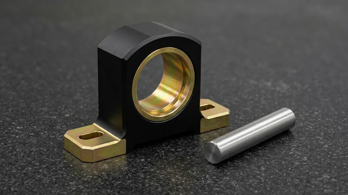
This selective dual-finish strategy is demonstrated on the 3-axis CNC-machined 6061-T6 aluminum pillow-block bearing housing below. Its exterior features matte black anodizing, while the precision-reamed bearing through-bore (with internal retaining ring groove) and slotted base mounting flanges are selectively finished in golden conductive chromate conversion film beside a cylindrical steel pin gauge.
DFM Geometry Rules for Wet Conversion Coating Lines
To prevent acidic chemical entrapment, hydrogen gas air pockets, galvanic halo defects, and masking cost escalations on 3-axis and 4-axis CNC milled housings or formed sheet metal assemblies, mechanical design engineers should apply four shop-floor DFM guidelines during 3D CAD modeling and 2D tolerance specification:
- Provide Drainage & Venting Holes in Deep Pockets: Blind pockets with depth-to-width ratios > 3:1 and enclosed tubular weldments trap acidic chromate solution. Incorporate Ø3.0 to Ø5.0 mm (0.118″ to 0.197″) drainage holes at opposing low corners so solutions drain freely during rack transfer.
- Avoid Overlapping Spot-Welded Lap Joints Before Dipping: Capillary gaps (0.05–0.25 mm / 0.002″–0.010″) between spot-welded sheet metal flanges wick alkaline etchant and nitric acid during immersion, bleeding out days later to corrode the seam. Chem-film individual sheet metal details prior to riveting or structural bonding whenever possible.
- Install Dissimilar Metal Hardware After Conversion Coating: Never immerse aluminum parts containing pre-installed carbon steel dowel pins, stainless steel helicoils, or brass threaded inserts into fluoride-activated conversion baths. The bimetallic couple triggers rapid galvanic etching of the surrounding aluminum halo and contaminates the conversion tank.
- Specify Clear Masking Boundary Tolerances on 2D Prints: When calling out dual-finish anodize plus Class 3 chem film, provide a ±0.80 mm (±0.031″) transition zone tolerance around taped grounding pads, or specify a stepped boss raised by 0.50 mm (0.020″) to create a natural mechanical masking edge.
6. Defect Troubleshooting, Metrology Verification & Shop-Floor Quality Control
Because chromate conversion coatings have nanometer-to-micrometer (0.25–1.5 µm / 10–60 µin) thickness and an amorphous gel structure, standard eddy-current coating thickness probes cannot resolve a 0.3 µm (0.000012″) film over machined roughness peaks. Instead, our 20°C ± 1°C (68°F ± 1.8°F) climate-controlled metrology laboratory and finishing QC team execute process-coupled verification protocols paired with precision dimensional inspection.
Dimensional features on conversion-coated parts are verified using GO/NO-GO thread gauges, smooth pin gauges, Mitutoyo 3-point bore micrometers, 2.5D optical Vision Measurement Systems (VMS), Mitutoyo SJ-210 profilometers (ISO 4287), and our Zeiss Contura bridge CMM (on request). Coating quality is audited via gravimetric strip-and-weigh coupons, ASTM D3359 tape adhesion tests, four-wire Kelvin probes, and ASTM B117 salt-spray panels.
| Observed Coating Defect | Root Physical / Chemical Cause | Affected Alloys & Features | In-House Inspection Detection | Recommended Application / Corrective DFM Action |
|---|---|---|---|---|
| Powdery / Chalky Rub-Off Film | Excessive immersion time (> 5 min), bath pH too low (< 1.3), or excessive fluoride activator concentration causing loose gel precipitation | All wrought alloys (especially Class 1A heavy builds on 6061-T6 and 2024-T3) | White cloth wipe test & ASTM D3359 pressure-sensitive tape pull test after 24h aging | Titrate free fluoride and adjust bath pH to 1.6–2.0 (Type I) or 3.7–3.95 (Type II); cap Class 1A immersion time to 60–180 seconds |
| Thermal Mud-Cracking & Early Salt-Spray Pitting | Drying or baking Type I hexavalent film above 60°C (140°F), driving off bound hydration water from Cr2O3·xH2O hydrogel | Unpainted Type I Class 1A and Class 3 parts exposed to hot air ovens or heat-curing adhesives | 200× VMS optical inspection & premature white rust (< 72h) in ASTM B117 neutral salt spray | Restrict drying air below 55°C (131°F); switch to Type II trivalent Zr/Cr (SurTec 650) if assembly requires > 60°C curing |
| Elevated Contact Resistance (> 5,000 µΩ/in²) | Residual silicated alkaline cleaner film or overly thick Class 1A gel applied to a Class 3 RF grounding surface | 5G RF filter cavities, waveguide flanges, and EMI chassis grounding pads | 4-wire Kelvin micro-ohmmeter test under 1.38 MPa (200 psi) electrode clamping load | Use strictly non-silicated alkaline cleaner, active nitric-fluoride desmut, and 30–60s immersion in Type II Class 3 TCP bath |
| Caustic / Acid Bleed-Out Staining | Entrapped cleaning or chromate solution weeping out of blind M2–M4 tapped holes or tight sheet metal lap joints during drying | Deep blind threaded holes, spot-welded enclosures, and unvented hollow frames | 100% visual inspection around thread mouths and lap seams under 5500K inspection lamps | Design through-drilled holes or add Ø3.5 mm drainage vents; flush blind threads with DI water ultrasonic agitation and air-knife blowoff |
| Dark Grey / Black Smut Streaking | Incomplete removal of insoluble copper/zinc intermetallics (7075/2024) or elemental silicon (ADC12/A380) during desmutting | 7075-T651 aerospace brackets, 2024-T3 plates, and A380/ADC12 die-cast housings | Pre-conversion water-break and white wipe check immediately after acid desmut rinse | Minimize alkaline etch time (< 30s) on 2024/7075 and fortify nitric acid desmut with 2.0–3.5 g/L fluoride activator |
| Bare Circular Halo Around Inserts | Galvanic potential difference between aluminum and pre-installed stainless steel or brass hardware polarizing the surrounding rim | Sheet metal panels with self-clinching nuts or CNC blocks with pre-pressed steel dowel pins | Visual ring inspection & localized salt-spray pitting audit around fastener bosses | Always execute chromate conversion coating on bare aluminum first, then press-fit PEM hardware, helicoils, and dowel pins post-coating |
7. When NOT to Specify Chromate Conversion Coating: Process Limitations, Trade-Offs & Lead Times
While chromate conversion coating is unmatched for thin-film electrical conductivity, zero dimensional shift, and atmospheric corrosion inhibition, specifying it in abrasive or harsh chemical environments leads to premature field failure. Hardware engineers should evaluate four critical process boundaries before finalizing their surface finish callout:
- Zero Abrasion or Sliding Wear Resistance: A 0.5 µm (0.00002″) conversion hydrogel offers virtually zero surface hardness improvement over raw 6061-T6 aluminum (~95 HB / ~105 HV). Never specify standalone chem film on sliding linear shafts, cam followers, or dynamic O-ring bores; choose MIL-A-8625 Type III hardcoat anodizing (450–550 HV) or high-phosphorus electroless nickel plating (ENP, 500–600 HV as-plated) instead.
- Vulnerability to Handling Scratches During First 24 Hours: While wet and freshly dried, the gelatinous conversion layer is soft and easily scraped by metal bins or rough handling. Only after 16 to 24 hours of ambient aging does the gel coalesce into a tough hydrophobic barrier.
- Non-Uniform Cosmetic Color Appearance: Unlike dyed Type II anodizing or powder coating, chromate conversion coating is an optical interference film whose golden, amber, or faint bluish-iridescent hue varies naturally with substrate grain orientation, silicon content, and local flow patterns. Never specify chem film as an exterior cosmetic finish on consumer products requiring strict CIELAB ΔE color uniformity.
- Acidic pH Attack Limit (pH < 3.0 or pH > 9.5): Although highly resistant to neutral chloride salt fog (pH 6.5–7.2), conversion films dissolve rapidly in strong mineral acids or caustic alkaline washdowns.
Ex-Factory Turnaround Schedule & Relative Cost Architecture
To support predictable hardware launch schedules across prototype and production phases, our Shenzhen facility structures all manufacturing timelines around transparent Ex-Factory Production & Inspection Turnaround, which is strictly separated from 3 to 5 business days of international express air transit (DHL, FedEx, or UPS):
- Rapid As-Machined CNC Prototypes (Unfinished): 4 to 8 business days ex-factory turnaround.
- CNC Prototypes with Global MIL-DTL-5541 Type I or Type II (Class 1A / Class 3) Coating: 7 to 12 business days ex-factory turnaround (1.0x baseline surface finishing cost index, including 24-hour film aging and QC verification).
- Hybrid Selective Dual-Finish Parts (Type II/III Anodize + Masked Class 3 Chem Film): 7 to 12 business days ex-factory turnaround for prototypes (1.35x to 1.65x relative finishing cost index due to manual silicone plugging, precision tape masking, or secondary CNC skim-milling setups).
- Low-to-Mid Volume Production Batches (10 to 1,000+ Parts): 7 to 30 business days ex-factory turnaround with batch lot traceability and full dimensional inspection reports.
🔗 Related Surface Finishing & Electronics CNC Engineering Guides
- Aluminum Surface Coatings Guide: Comparing Anodizing, Chem Film, Powder Coating & Electroplating
- How Anodizing Improves Electronic Products: Dielectric Isolation, Thermal Emissivity & Selective EMI Grounding
- CNC Machining for the Electronics Industry: RF Shielding Enclosures, Heat Sinks & Tight-Tolerance DFM
8. Technical Engineering FAQ
Chromate conversion coating forms an ultra-thin chemical conversion film measuring only 0.25 to 1.5 µm (0.00001″ to 0.00006″) thick via superficial substrate redox reaction. Consequently, precision CNC features such as ISO H7 bearing bores and fine tapped threads require zero pre-machining dimensional compensation.
MIL-DTL-5541 Type I formulations utilize hexavalent chromium (Cr⁶⁺) to create a self-healing golden-amber barrier restricted primarily to legacy defense exemptions. Conversely, Type II formulations employ trivalent chromium (Cr³⁺ TCP / SurTec 650) that satisfies RoHS and REACH directives while delivering comparable salt-spray protection.
Engineers should specify Class 3 whenever aluminum components require low electrical contact resistance below 5,000 µΩ/in² for EMI/RFI shielding gaskets, RF waveguide flanges, or chassis ground lugs. Specify Class 1A for structural components prioritizing maximum 168-to-336-hour ASTM B117 corrosion defense or paint primer adhesion.
Exposing newly formed hexavalent chromate conversion coatings to temperatures above 60°C (140°F) per ASTM B449 drives off bound hydration water from the amorphous chromium hydroxide gel. This thermal dehydration fractures the protective film into micro-cracks and permanently destroys its active self-healing corrosion resistance.
Ready to Optimize Your Custom Parts for Precision Manufacturing?
Upload your 3D CAD models and 2D drawings for a comprehensive DFM review covering MIL-DTL-5541 Type I and RoHS Type II conversion coatings, selective anodize masking, and tight-tolerance CNC machining. Our in-house engineering team will verify your grounding pad layouts, bore tolerances, and alloy selection to ensure defect-free production.
Request a Technical DFM & Custom Quote →