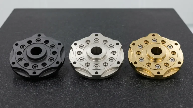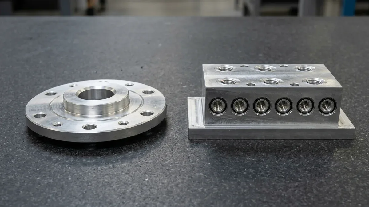
Evaluating vertical vs horizontal milling is one of the most consequential process-routing decisions in precision CNC manufacturing. While a Vertical Machining Center (VMC) aligns its spindle axis vertically along the Z-axis perpendicular to a horizontal worktable, a Horizontal Machining Center (HMC) orients its spindle horizontally parallel to the shop floor alongside an indexing rotary B-axis pallet.
That 90-degree kinematic shift fundamentally alters gravitational chip evacuation, workholding density, datum stack-up, and spindle utilization. On our Shenzhen shop floor, high-speed 3-axis and 4-axis VMCs handle 75% to 85%+ of rapid prototypes and planar parts, whereas 4-axis HMCs with multi-sided tombstone fixtures excel on multi-face manifolds and housings from 30–50+ pieces to volume runs.
In this engineering DFM guide, our in-house manufacturing team quantifies the mechanical, thermal, and economic crossover boundaries between vertical and horizontal milling. We examine structural load paths, cantilever tool deflection, deep-cavity chip evacuation physics, B-axis tombstone cycle-time mathematics, ISO 2768-mK and precision ±0.010 mm (±0.0004 in) tolerance capabilities, and actionable design rules for custom machined parts.
Executive Summary & Engineering Takeaways (BLUF)
- Shop-Floor Capacity Allocation (3/4-Axis VMC Workhorse): High-speed 3-axis and 4-axis VMCs execute 75%–85%+ of prototype and short-run batches using precision steel machine vises, subplates, or contoured aluminum soft jaws, achieving 4–8 business days ex-factory turnaround.
- Spindle Utilization & Tombstone Economics: Dual-pallet 4-axis HMCs mounting 8–16 parts on 4-sided B-axis tombstones boost spindle green-light utilization from 45%–60% (standalone VMC) to 85%–92%, slashing per-unit tool-change and loading overhead by over 80%.
- Gravity-Assisted Chip Evacuation: Horizontal spindle orientation lets chips fall directly into the bed auger conveyor, preventing chip recutting in pockets deeper than 3×D and maintaining Ra 0.8 µm (32 µin) surface finishes per ISO 4287.
- Multi-Face Positional Tolerance Integrity: Single-setup B-axis indexing (0°, 90°, 180°, 270°) holds orthogonal bore-to-bore coordinate spacing within ±0.010 mm to ±0.020 mm (±0.0004 in to ±0.0008 in) and true position within ⌀0.015 mm to ⌀0.025 mm (⌀0.0006 in to ⌀0.0010 in), eliminating manual 4-op flip-over datum stack-up.
- Volume & Geometry Crossover Threshold: Route planar plates, heat sinks, and shallow brackets to 3-axis VMCs; route multi-face valve manifolds and gearbox housings to 4-axis HMC modular tombstones at ≥ 30–50+ pieces (or ≥ 150–200+ pieces for custom dedicated tombstone fixtures).
Article Engineering Navigation
- 1. Spindle Orientation Kinematics & Frame Rigidity
- 2. Why 3/4-Axis VMCs Dominate Prototype Production
- 3. Gravity Chip Evacuation & Tool Deflection Physics
- 4. B-Axis Tombstone Fixturing & Cycle-Time Math
- 5. VMC vs. HMC Engineering Specification Matrix
- 6. Multi-Face Tolerances, RSS Math & DFM Matrix
- 7. When NOT to Choose Horizontal Milling
- 8. Technical Engineering FAQ
1. Spindle Orientation Kinematics & Structural Frame Rigidity
The primary mechanical distinction between vertical and horizontal machining centers lies in how the spindle carrier, column casting, and worktable transmit cutting forces into the cast-iron bed. Under ISO 841 axis nomenclature, the spindle axis is always designated Z: a 3-axis VMC moves its spindle vertically in Z while the table translates horizontally in X and Y.
Because a VMC uses a C-frame overhang structure to clear the worktable throat depth, heavy radial cutting forces create a bending moment arm against the vertical column ways. When roughing pre-hardened 4140 alloy steel (28–32 HRC) or 17-4PH stainless steel with large-diameter indexable cutters, this cantilever overhang limits maximum radial engagement before chatter harmonics emerge.
Conversely, a 4-axis Horizontal Machining Center (HMC) mounts a dual-contact BBT40, HSK-A63, or high-torque BT50/CAT50 spindle horizontally inside a symmetric box column, orienting tombstone height along the vertical Y-axis. Cutting thrust acts directly into box ways near the bed, raising dynamic loop stiffness by 30%–50% over a C-frame VMC.
Furthermore, HMCs integrate a 400 × 400 mm (15.7 × 15.7 in) or 500 × 500 mm (19.7 × 19.7 in) pallet into a rotary B-axis table (360° around the vertical Y-axis per ISO 841 with 0.001° indexing). Matching these kinematics within our CNC milling services routes wide plates to VMCs and multi-face blocks to HMCs.
2. Why 3-Axis & 4-Axis VMCs Dominate Prototype & Short-Run Production
Despite the high-volume throughput of horizontal machining cells, high-speed 3-axis and 4-axis VMCs remain the undisputed workhorses of precision prototyping and low-to-medium volume manufacturing. Across our in-house CNC machining facility, 3-axis and 4-axis vertical centers represent 75% to 85%+ of active spindle capacity for rapid prototypes and short-run batches.
First, VMC workholding relies on standardized precision steel machine vises, contoured aluminum soft jaws, modular subplates, or low-profile toe clamps bolted directly to a horizontal T-slot table. Gravity naturally seats the raw billet flat against precision parallel bars while the operator tightens the vise, enabling 15-minute job changeovers and zero custom tombstone NRE.
Second, vertical spindle orientation provides unobstructed top-down operator visibility during first-article setup, wireless touch-probe datum registration, and toolpath verification. Third, adding a 4th-axis horizontal rotary indexer (A-axis) onto a VMC table allows 360-degree indexing on cylindrical sleeves, clevis yokes, and brackets while retaining the fast setup agility of a vertical platform.
In the setup below, a 7075-T6 aluminum figure-eight twin-bore bearing linkage plate (140 × 18 mm / 5.51 × 0.71 in) is gripped securely across its concave central waist inside contoured aluminum soft jaws on a 3-axis VMC, where an 8 mm (0.315 in) 4-flute solid carbide end mill finishes the R5 mm (0.197 in) pocket corners.
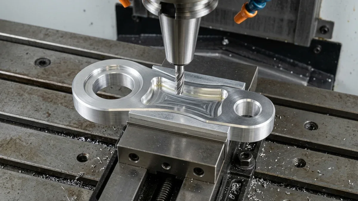
By contouring the aluminum soft jaws to match the concave waist profile of the linkage plate, clamping pressure distributes evenly around the thin web surrounding the primary bearing bore. This prevents elastic springback when the vise opens, holding bore diameter (ISO H7) and center-to-center spacing within ±0.012 mm (±0.0005 in) within a 4–8 business days ex-factory prototype turnaround.
3. Gravity-Assisted Chip Evacuation, Deep-Pocket Physics & Tool Deflection
When pocket depth exceeds three times the cutter diameter (L/D ≥ 3:1), chip evacuation and tool stickout transition into the primary physical constraints governing tool life, dimensional accuracy, and surface integrity. In vertical milling, gravity pulls severed metal chips directly downward onto the floor of the pocket or blind cavity being cut.
Unless flushed out instantaneously by high-pressure through-spindle coolant (20–70 bar / 290–1,015 psi) or compressed-air jets, trapped chips are repeatedly pinched between the rotating carbide cutting edges and the freshly machined wall. In work-hardening alloys such as 304/316L stainless steel and Ti-6Al-4V titanium, chip recutting causes localized thermal spikes above 650 °C (1,202 °F) and built-up edge welding.
Horizontal milling reverses this gravitational vector completely. Because the workpiece clamping face stands vertically on the tombstone column and the spindle approaches horizontally, sheared chips fall straight down out of the cavity the instant they leave the shear zone, dropping unhindered into the dual-auger chip conveyor below the rotary pallet.
High-speed milling carries away 75% to 80% of cutting heat inside the evacuated chip curl while only 10% to 15% conducts into the workpiece billet. Moreover, B-axis indexing on an HMC lets operators approach deep multi-sided features from orthogonal directions using stub-length cutters, drastically reducing radial cantilever tool deflection:
δ = (Fr × L3) ÷ (3 × E × I), where radial force is Fr (N), tool stickout is L (mm), carbide elastic modulus is E ≈ 600 GPa (87.0 × 10⁶ psi), and area moment of inertia is I = (π × de4) ÷ 64.
- Long-Reach Setup (L = 60 mm / 2.362 in, L/D = 5:1): Side-milling a manifold wall with a ⌀12 mm (0.472 in) solid carbide end mill (effective flute core de = 9.6 mm / 0.378 in, I = 416.9 mm4) under radial load Fr = 450 N (101.2 lbf) produces δ = 0.130 mm (0.0051 in) tip deflection, causing wall taper and chatter.
- B-Axis Indexed Stub Setup (L = 36 mm / 1.417 in, L/D = 3:1): Rotating the tombstone via B-axis to approach the feature orthogonally with a stub cutter slashes cubic deflection by 78.4% down to δ = 0.028 mm (0.0011 in).
4. B-Axis Tombstone Fixturing, Dual Pallet Changers & Spindle Utilization Math
The decisive economic advantage of horizontal milling in batch production stems from combining 4-sided rotary B-axis tombstone columns with twin Automatic Pallet Changers (APC). Using modular grid or zero-point tombstones, complex 4-sided manifolds and housings reach break-even on an HMC at 30–50+ pieces, whereas custom dedicated tombstone subplates amortize cleanly above 150–200+ pieces.
On a standalone 3-axis VMC, the spindle stops whenever the operator opens the enclosure doors to clear chips, flip parts, and re-probe offsets, yielding 45%–60% spindle green-light utilization. On a 4-axis HMC with a dual-station APC, the spindle cuts Pallet A while the operator reloads raw billets onto Pallet B offline, swapping pallets in 6–10 seconds.
1. Effective Unit Part Cycle Time (tunit) & Amortized Non-Cutting Overhead (toverhead/part):
tunit = tcut + toverhead/part = tcut + [(tATC × Ntools) + (tindex × Nfaces) + tswap] ÷ Nparts — summing net cutting, tool-change, B-axis index, and pallet-swap seconds amortized across Nparts tombstone workpieces.
2. Volumetric Material Removal Rate (Q / MRR) & Net Spindle Power (Pc):
Q = MRR = (ap × ae × vf) ÷ 1,000 [cm³/min] and Pc = (Q × kc) ÷ 60,000 [kW], given axial depth ap (mm), radial width ae (mm), feed rate vf (mm/min), and specific cutting force kc (N/mm²).
3. Amortized Batch Setup Crossover Volume (Ncrossover):
Ncrossover = (Tsetup,HMC − Tsetup,VMC) ÷ (tunit,VMC − tunit,HMC) — where Tsetup is total fixture build and probing setup time (s) and tunit is effective per-part cycle time (s).
- Volumetric MRR & Spindle Power Benchmark (6061-T6 Roughing at ap = 20 mm / 0.787 in, vf = 3,200 mm/min / 126.0 in/min, kc = 750 N/mm²): Stepping radial engagement ae from 4.0 mm (0.157 in) on a C-frame VMC to 5.4 mm (0.213 in) on a rigid box-way HMC raises MRR from 256.0 cm³/min (15.62 in³/min) to 345.6 cm³/min (21.09 in³/min) (+35.0%), drawing Pc = 3.20 kW (4.29 hp) vs. 4.32 kW (5.79 hp).
- Single-Vise 3-Axis VMC Benchmark (3 Manual Flip Setups, Nparts = 1, 10 Tools): Net cutting time tcut = 420 s; tool changes = 10 × 5.5 s = 55 s; 3 manual unclamping/flipping/loading cycles tswap = 3 × 45 s = 135 s. Total tunit, VMC = 610.0 s (10.17 min/part), with 190 s (31.1%) lost to non-cutting overhead.
- 12-Part 4-Axis HMC Tombstone with APC (3 Parts × 4 Faces, Nparts = 12, 10 Tools): Gravity chip evacuation and higher MRR trim tcut to 370 s; tool-change overhead drops to (5.5 s × 10) ÷ 12 = 4.58 s/part; B-axis indexing = (4 × 2.0 s) ÷ 12 = 0.67 s/part; APC swap = 9.0 s ÷ 12 = 0.75 s/part. Total tunit, HMC = 376.0 s (6.27 min/part) — cutting non-cutting overhead by 96.8% and total cycle time by 38.4%.
- Batch Volume Crossover Calculation (Ncrossover): With modular tombstone setup Tsetup,HMC = 195 min (11,700 s) versus 3-op VMC vise setup Tsetup,VMC = 45 min (2,700 s), net setup investment ΔTsetup = 9,000 s divided by unit cycle savings Δtunit = 610.0 − 376.0 = 234.0 s/part yields Ncrossover = 9,000 ÷ 234.0 = 38.5 parts (≈ 39 pcs), confirming the 30–50+ piece modular HMC break-even window.
To capture these multi-station efficiencies across our CNC machining services, our manufacturing engineers follow a standardized 4-step qualification protocol whenever transitioning a multi-sided part from prototype VMC vises into production HMC tombstone cells, ensuring repeatable datum integrity across every pallet swap:
- Consolidate Multi-Face Datum Schemes to a Primary Mounting Flange (Datum A): Bolt the base flange onto a B-axis pallet riser with dowel pins to expose all four vertical perimeter faces (0°, 90°, 180°, 270°), or onto a vertical tombstone face to access the outward and side faces.
- Deploy Window Fixtures for Dual-Face Access: For thin-walled die-cast A380 or billet 6061-T6 housings, mount parts inside open window-frame fixtures so the horizontal spindle machines both front (B = 0°) and rear (B = 180°) faces in one clamping.
- Sequence CAM Toolpaths in Tool-Dominant Mode: Program the post-processor so each roughing end mill, drill, and tap finishes all 12 workpieces across all four tombstone faces before commanding a single automatic tool change.
- Calibrate Dynamic B-Axis Center-of-Rotation Offsets (G54.1 P1–P48): Probe a precision calibration sphere on each tombstone face with an optical spindle touch probe to compensate for thermal growth within ±0.005 mm (±0.0002 in) and hold rotary total indicator runout (TIR) ≤ 0.005 mm (0.0002 in).
5. Quantitative VMC vs. HMC Engineering Specification & Selection Matrix
Selecting the optimal milling platform requires weighing part envelope, number of machined faces, cavity depth-to-width ratio, positional GD&T callouts, and batch volume against fixture setup amortization. You can inspect our specific vertical, horizontal, and multi-axis machine centers on our manufacturing equipment list before finalizing your production routing.
| Engineering Parameter | 3-Axis / 4-Axis Vertical Milling (VMC) | 4-Axis Horizontal Milling (HMC) | Recommended Application / When to Choose |
|---|---|---|---|
| Spindle & Table Kinematics (ISO 841) | Vertical Z-axis spindle (BT40 / BBT40 / HSK-A63) perpendicular to horizontal X-Y table (optional A-axis rotary indexer) | Horizontal Z-axis spindle (dual-contact BBT40 / HSK-A63 / BT50 / CAT50); vertical Y-axis column; integrated B-axis rotary table (360° around Y, 0.001° indexing) | Choose VMC for 1–2 face planar parts; choose HMC for 3–5 face orthogonal prismatic blocks |
| Chip Evacuation Physics | Gravity traps chips in blind pockets; requires 20–70 bar (290–1,015 psi) coolant or air blast | Gravity drops chips straight down into auger conveyor; zero chip pooling in deep cavities | Choose HMC for deep pockets (L/D ≥ 3:1) and high-MRR roughing in 304/316L, 4140, or 7075 |
| Workholding & Fixture Architecture | Precision steel machine vises, contoured aluminum soft jaws, vacuum plates, toe clamps | 4-sided tombstone columns, window fixtures, hydraulic zero-point chucks on dual 400×400 or 500×500 mm APC pallets | Choose VMC for rapid zero-NRE vise clamping; choose HMC when multi-face batch volume justifies tombstones |
| Spindle Utilization (“Green-Light Time”) | 45%–60% (spindle pauses during manual door opening, chip blow-off, and part reloading) | 85%–92% (concurrent offline part loading on Pallet B during active cutting on Pallet A) | Choose HMC for multi-sided batches ≥ 30–50+ pcs (modular grid) or ≥ 150–200+ pcs (custom fixtures) |
| Multi-Face Coordinate & GD&T Tolerance | Linear: ±0.025–0.040 mm (±0.0010–0.0016 in); True Position: ⌀0.050 mm (⌀0.0020 in) across 3–4 manual flips | Linear: ±0.010–0.020 mm (±0.0004–0.0008 in); True Position: ⌀0.015–0.025 mm (⌀0.0006–0.0010 in) in 1 clamping | Choose HMC when orthogonal faces require coaxiality ≤ ⌀0.015 mm or perpendicularity ≤ 0.015 mm (0.0006 in) |
| General & Precision Feature Tolerances | General: ISO 2768-mK; single-setup precision bores: ±0.010 mm to ±0.020 mm (±0.0004–0.0008 in) | General: ISO 2768-mK; precision reamed/bored seats: ±0.010 mm to ±0.020 mm (±0.0004–0.0008 in) | Both hold identical single-face bore accuracy; pair with Wire EDM / Grinding for ±0.005 mm (±0.0002 in) |
| Achievable Surface Roughness (ISO 4287) | As-machined: Ra 1.6–3.2 µm (63–125 µin); fine face/flank finish: Ra 0.8 µm (32 µin) | As-machined: Ra 0.8–1.6 µm (32–63 µin); deep cavity walls: Ra 0.4–0.8 µm (16–32 µin) | Choose HMC when deep pocket walls or O-ring boss seats demand scratch-free Ra 0.8 µm (32 µin) |
| Relative Hourly Machine & Setup Index | Baseline Machine Rate Index: 1.0x | Setup & Fixture NRE: Low (Standard Vises) | Machine Rate Index: 1.4x–1.8x | Setup & Tombstone Fixture NRE: Moderate to High | VMC minimizes cost for 1–50 pcs (blocks) or 1–200 pcs (plates); HMC cuts unit cost 25%–40% at volume |
| Ex-Factory Turnaround Lead Time | 4–8 business days (as-machined prototypes); 7–12 business days (with anodizing/plating) | 7–12 business days (initial tombstone setup + short run); 7–30 business days (production runs) | Ex-factory production & QC turnaround; add 3–5 business days for DHL/FedEx/UPS air transit |
6. Multi-Face Positional Tolerances, RSS Datum Stack-Up & Metrology
A common misconception is assuming horizontal machining centers are inherently more accurate on single bore diameters than vertical centers. When boring or reaming an individual perpendicular hole, both modern VMCs and HMCs hold ±0.010–0.020 mm (±0.0004–0.0008 in) critical tolerances—such as ⌀18–30 mm ISO 286 H7 (+0.021/−0.000 mm) or JS7 (±0.0105 mm) bearing seats—alongside ISO 2768-mK general tolerances.
Where 4-axis horizontal milling delivers a major accuracy leap is in inter-surface geometric dimensioning and tolerancing (GD&T per ASME Y14.5) across three or four orthogonal faces. On a 3-axis VMC, machining a 4-sided valve manifold requires four manual vise clampings, where each re-clamping and edge-probing cycle introduces independent datum transfer error.
σtotal = √(∑ σi2) = √(n × σclamp2 + σspindle2), where n is manual clamping transfers, σclamp is per-setup fixture seating/probing error, and σspindle is machine positioning repeatability.
- 4 Manual VMC Vise Flips (n = 4): With σclamp = ±0.012 mm (±0.00047 in) and σspindle = ±0.006 mm (±0.00024 in), RSS stack-up reaches σtotal, VMC = √(4 × 0.0122 + 0.0062) = ±0.025 mm (±0.0010 in) (worst-case linear sum ±0.054 mm / ±0.0021 in).
- Single-Clamping 4-Axis HMC B-Axis Index: Using a curvic-coupling B-axis rotary table (σB-index = ±0.004 mm / ±0.00016 in), single-setup error drops by 70.9% to σtotal, HMC = √(0.0042 + 0.0062) = ±0.0072 mm (±0.00028 in).
Because all four orthogonal vertical faces of an automotive powertrain housing or hydraulic manifold are machined in one clamping on an HMC B-axis pallet riser or window tombstone, intersecting cross-bores maintain coordinate alignment within ±0.012 mm (±0.0005 in) and true position within ⌀0.015 mm to ⌀0.025 mm (⌀0.0006 in to ⌀0.0010 in).
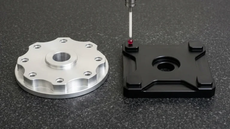
As shown in our metrology inspection setup below, a 4-axis HMC-machined 6061-T6 aluminum multi-boss valve manifold body with a continuous closed-loop O-ring groove, raised perimeter mounting bosses, and orthogonal threaded side fluid ports undergoes first-article verification on a black granite surface plate using a vertical bridge CMM spherical ruby ball stylus.
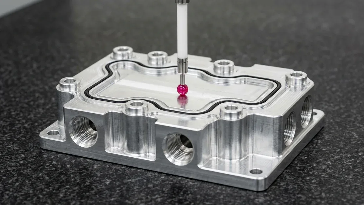
In our 20 °C ± 1 °C (68 °F ± 1.8 °F) Shenzhen metrology lab, multi-sided parts are verified via Zeiss Bridge CMM (upon request), 2.5D Optical VMS, 3-point bore micrometers, Go/No-Go thread/pin gauges, stylus profilometers (ISO 4287), and 3.5–6.0 bar (50–87 psi) pressure-decay leak testers, with a Ballooned Drawing & Full-Dimensional FAI Report (Form 1/2/3 Layout).
| Machining Defect / Failure Mode | Physical Root Cause (VMC vs. HMC) | Shop-Floor DFM & Process Countermeasure | Recommended Application / Verification |
|---|---|---|---|
| Scored Pocket Walls & Premature Flute Chipping | Gravity chip pooling in VMC blind cavities (depth ≥ 3×D) causing severe chip recutting and built-up edge | Route deep-pocket parts to 4-axis HMC for gravity chip fall, or apply 40 bar (580 psi) through-spindle coolant with trochoidal toolpaths on VMC | Verify wall finish ≤ Ra 0.8 µm (32 µin) using stylus profilometer per ISO 4287 |
| Orthogonal Cross-Bore Mismatch (Internal Step > 0.03 mm) | Cumulative RSS datum transfer error (σtotal ≥ ±0.025 mm) across 3–4 manual vise flips on a 3-axis VMC | Machine all 4 orthogonal faces in a single clamping setup using B-axis indexing (0°, 90°, 180°, 270°) on a 4-axis HMC or 4-axis rotary indexer | Verify bore-to-bore true position (⌀0.020 mm / ⌀0.0008 in) and center spacing (±0.012 mm) via Bridge CMM or Go/No-Go pin gauges |
| Thin-Wall Housing Distortion After Unclamping | Excessive two-point vise jaw squeezing force on thin 1.5–2.5 mm (0.059–0.098 in) aluminum walls | Use full-contact contoured aluminum soft jaws on VMC, or face-bolt the part’s mounting flange onto an HMC tombstone with torque-limited fasteners | Inspect bore diameter with 3-point internal bore micrometer and flatness on granite surface plate |
| Chatter Marks on Deep Vertical Sidewalls | Excessive tool stickout (L/D > 5:1) driving cubic cantilever deflection δ = (Fr × L3) ÷ (3EI) during flank milling | Design vertical pocket corner radii R ≥ 1/3 cavity depth so stubby variable-helix carbide end mills in thermal shrink-fit holders can engage cleanly | Recommended for structural 7075-T6 aerospace/robotics brackets and 4140 steel manifolds |
| Y-Axis Thermal Drift Across Tombstone Height | Vertical thermal expansion ΔY = αtombstone × Hy × ΔT along a 600 mm (23.6 in) tombstone tower (ΔT = 3 °C / 5.4 °F shifts GGG40 cast iron [α = 10.5 µm/m·°C] by +0.019 mm / 0.0007 in, or 6061-T6 aluminum [α = 23.1 µm/m·°C] by +0.042 mm / 0.0016 in) | Use thermally stable GGG40 ductile iron tombstones and execute in-cycle spindle touch-probe datum calibration on each station before finishing ±0.010 mm (±0.0004 in) bores | Essential for multi-station batches (50–5,000+ pcs) with tight bore-to-datum height tolerances |
7. When NOT to Choose Horizontal Milling: Process Limitations & Trade-Offs
While 4-axis horizontal machining centers excel at multi-sided batch production, routing every custom component to an HMC is a costly engineering mistake. In three specific manufacturing scenarios, horizontal milling introduces unnecessary fixture overhead, gravity overhang deflection, or kinematic bottlenecks compared to 3-axis VMC or 5-axis trunnion milling:
- Low-Volume Prototypes & Single-Piece R&D Iteration (1–30 Pieces): Designing, machining, and qualifying a multi-station 4-sided tombstone sub-plate with precision dowel locations requires non-recurring engineering (NRE) setup time. For quantities under 30 pieces (or under 150–200 pieces for simple 2-face parts), clamping raw bar stock directly in a 3-axis VMC vise or contoured soft jaw delivers parts in 4–8 business days with minimal setup cost.
- Wide, Thin Planar Baseplates & Large Heat Sinks (Aspect Ratio W/T ≥ 15:1): Hanging a 600 × 450 × 12 mm (23.6 × 17.7 × 0.47 in) aluminum baseplate vertically on the side of an HMC tombstone forces operators to fight gravity during loading and causes thin center webs to vibrate unless backed by custom vacuum plates. Laying flat plates horizontally on a 3-axis VMC bed provides full bottom support.
- Compound-Angle Aerospace Contours, Impellers & Blisks: Standard 4-axis HMCs rotate only around the vertical B-axis, leaving the top fifth face (perpendicular to the B-axis) and compound oblique undercuts inaccessible without an extra setup. Parts requiring continuous 5-axis surface interpolation or compound-angle ports should be routed directly to a simultaneous 5-axis trunnion machining center.
🔗 Related CNC Milling Engineering Guides
8. Technical Engineering FAQ
Choose 3-axis or 4-axis vertical milling for prototypes, planar plates, and short runs requiring low fixture overhead and 4 to 8 business days ex-factory turnaround. Select 4-axis horizontal milling with tombstone fixtures when batches exceed 30 to 50 multi-sided manifolds or housings needing automated pallet swapping.
Horizontal machining centers orient the spindle parallel to the shop floor so gravity pulls evacuated chips directly downward into the bed auger conveyor. Eliminating chip pooling prevents carbide flutes from recutting work-hardened swarf, extending tool life by 30% and maintaining Ra 0.8 µm (32 µin) cavity walls.
Precision 4-axis horizontal machining centers indexing a rotary B-axis tombstone hold ±0.010 mm to ±0.020 mm (±0.0004 in to ±0.0008 in) coordinate tolerances and ⌀0.015 mm (⌀0.0006 in) true position across four faces. Non-critical features follow ISO 2768-mK general tolerances unless tighter datum fits are specified.
Four-sided tombstone columns mount 8 to 16 workpieces simultaneously so each cutting tool finishes identical features across multiple parts before a single tool change occurs. Combined with an 8-second dual pallet changer, non-cutting tool-change and loading overhead drops by over 80% compared to single-vise setups.
Ready to Optimize Your Custom Parts for Precision Manufacturing?
Upload your 3D STEP/IGES files and 2D GD&T drawings for an engineering DFM evaluation matching your part geometry and batch volume to our 3/4-axis VMC or 4-axis HMC tombstone cells. Our in-house Shenzhen machining team verifies datum schemes, pocket corner radii, and multi-face tolerance stack-up before cutting chip one.
Request a Technical DFM & Custom Quote →