In mechanical engineering design and precision holemaking, counterbores and spotfaces are two of the most ubiquitous geometric features used to accommodate threaded fasteners. While both features share the same underlying topology—a flat-bottomed, cylindrical enlargement coaxial with a through-hole or pilot bore—their functional design intent, Geometric Dimensioning and Tolerancing (GD&T) standards, and CNC machining strategies differ significantly.
Confusing a counterbore for a spotface on engineering prints can introduce unneeded machining cycle time or compromise joint integrity. This technical guide examines the functional distinctions, ASME Y14.5 and ISO drawing standards, fastener clearance charts, and modern CNC milling toolpath strategies for counterbores and spotfaces.
- 1. Fundamental Definitions: Counterbore vs. Spotface Design Intent
- 2. Drawing Standards & GD&T Callouts (ASME Y14.5 vs. ISO 1101)
- 3. Standard Metric Counterbore Dimensions & Clearance Hole Engineering Chart
- 4. CNC Machining Strategies: Helical Interpolation vs. Form Tools
- 5. DFM Design Guidelines for Machinists and Product Designers
- 6. Technical Engineering FAQ
1. Fundamental Definitions: Counterbore vs. Spotface Design Intent
Understanding the distinction begins with fastener seating mechanics and packaging constraints:
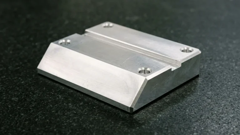
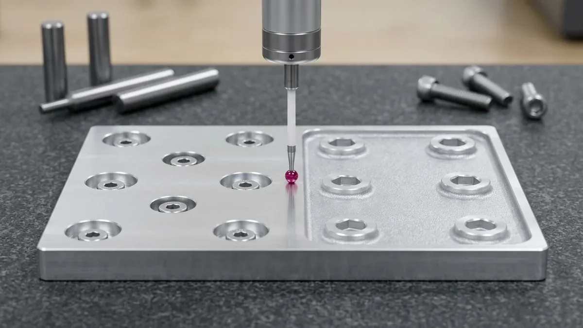
- Counterbore (C-Bore): A deep, flat-bottomed cylindrical recess designed to fully submerge the head of a fastener (such as an ISO 4762 / DIN 912 socket head cap screw) below or flush with the external mating surface of the workpiece. The depth is a primary functional dimension calculated to encapsulate both the screw head height and any accompanying hardened washer, preventing interference with adjacent sliding, rotating, or mounting assemblies.
- Spotface (S-Face): A very shallow, flat-bottomed circular surface designed purely to clean up an irregular, curved, inclined, or rough as-cast surface. Its purpose is not to conceal the bolt head, but to provide a smooth, planar, perpendicular bearing surface (typically achieving a perpendicularity within 0.05mm relative to the hole axis). Without a spotface on rough castings or forgings, the bolt head seats at an angle, inducing dangerous bending fatigue stresses across the fastener shank under pre-load.
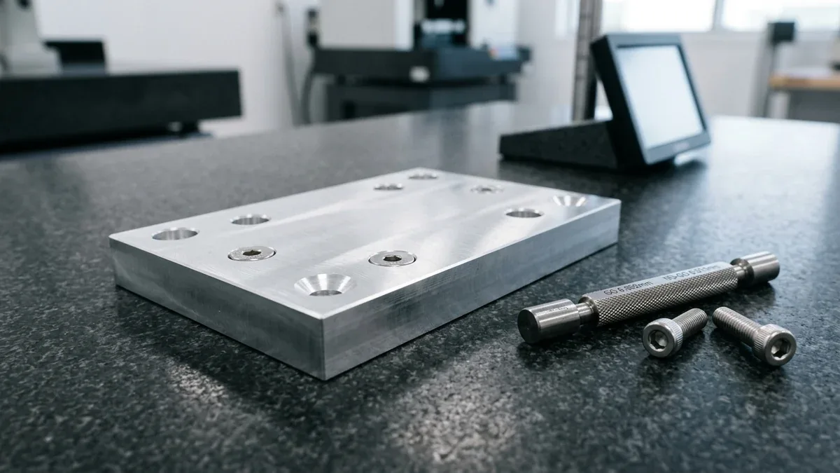
2. Drawing Standards & GD&T Callouts (ASME Y14.5 vs. ISO 1101)
On production engineering blueprints, counterbores and spotfaces are defined using standardized symbolic callouts to ensure zero ambiguity between design engineering and CNC machine shops:
- Counterbore Symbol (⌴): In ASME Y14.5 and ISO 1101, a counterbore is designated by an open-top rectangular symbol (⌴) followed by the counterbore diameter (⌀) and counterbore depth (↧). For example,
⌀ 6.6 ↧ THRU | ⌴ ⌀ 11.0 ↧ 6.5indicates an M6 clearance through-hole with an 11mm diameter counterbore machined to a depth of 6.5mm. - Spotface Symbol (SF ⌴): A spotface uses the counterbore symbol preceded or accompanied by the letters ‘SF’. Under ASME Y14.5-2018, if no depth is specified, the operator spotfaces just enough to clean up 100% of the surface area (indicated by
SF ⌴ ⌀ 20.0 MIN TO CLEAN). If depth is specified, it denotes the maximum allowable cut or remaining minimum boss thickness. - Perpendicularity & Flatness Controls: High-performance bolted assemblies often attach a GD&T perpendicularity refinement (e.g., perpendicularity within 0.05mm to Datum A) to the spotface or counterbore seat to prevent dynamic bending fatigue on high-tensile 10.9 or 12.9 grade fasteners under pre-load.
3. Standard Metric Counterbore Dimensions & Clearance Hole Engineering Chart
To avoid interference with standard ISO 4762 / DIN 912 socket head cap screws (SHCS) and ensure adequate tool clearance for magnetic hex drivers, engineering drawings should follow standard ISO clearance fits:
| Screw Size | Close Fit Hole (⌀mm) | Normal Fit Hole (⌀mm) | C-Bore Diameter (⌀mm) | Standard Depth (mm) | Depth with Washer (mm) |
|---|---|---|---|---|---|
| M3 | 3.2 | 3.4 | 6.0 | 3.4 | 4.0 |
| M4 | 4.3 | 4.5 | 7.5 | 4.4 | 5.2 |
| M5 | 5.3 | 5.5 | 9.0 | 5.4 | 6.4 |
| M6 | 6.4 | 6.6 | 11.0 | 6.5 | 8.0 |
| M8 | 8.4 | 9.0 | 14.5 | 8.6 | 10.5 |
| M10 | 10.5 | 11.0 | 17.5 | 10.6 | 13.0 |
| M12 | 13.0 | 13.5 | 20.0 | 12.6 | 15.5 |
4. CNC Machining Strategies: Helical Interpolation vs. Form Tools
In precision CNC machine shops, cutting counterbores and spotfaces efficiently depends on batch volume, feature depth, and tooling setups:
- Circular Helical Interpolation: Utilizing a standard 2-flute or 3-flute carbide end mill driven along a continuous helical toolpath (G02/G03 with continuous Z ramp) is the preferred method for prototype and low-volume CNC milling. It generates smaller, easily evacuated chips, avoids high axial plunge loads, and allows programmers to dial in exact diameter offsets (G41/G42) to maintain tight tolerances without custom tooling.
- Piloted Counterbore Cutters: Dedicated piloted counterbore tools feature an interchangeable or solid pilot that slides into the pre-drilled through-hole to guide multi-flute cutting edges. While ideal for high-volume transfer line production, piloted tools can bind if the through-hole has minor runout, and chip evacuation is restricted in deep pockets.
- Back Spotfacing Tools: When casting or forging geometry prevents spindle access to the reverse side of a mounting lug, reverse back-spotfacing tools (such as automated expandable wing cutters) allow the tool to pass through the clearance hole, expand cutting blades, and spotface the rear face in a single machine setup.
5. DFM Design Guidelines for Machinists and Product Designers
To optimize manufacturing throughput and eliminate costly machining bottlenecks, incorporate these Design for Manufacturability (DFM) rules:
- Standardize Counterbore Diameters: Consolidate counterbore sizes across a single component. Using M4 and M6 screws on the same housing rather than introducing an isolated M5 screw reduces tool changes and simplifies cycle times.
- Provide Adequate Radial Clearance: Ensure counterbore diameters provide sufficient radial clearance not only for the fastener head, but also for standard thin-walled hex sockets or magnetic bit holders if field maintenance is required.
- Specify Minimum Spotface Depth: On casting drawings, call out spotfaces with a maximum depth limit rather than an exact depth coordinate. Allowing the CNC machinist to “spotface to clean surface” accommodates raw casting wall variations while ensuring 100% planar contact.
- Verify Wall Thickness Under Counterbore: Ensure that deep counterbores leave sufficient residual structural wall thickness (at least 1.5x screw diameter) to withstand axial bolt tension without punching through under torque.
6. Technical Engineering FAQ
A counterbore is a deep flat-bottomed recess intended to fully submerge a fastener head beneath or flush with the workpiece surface, where depth is a critical dimension. A spotface is a shallow flat-bottomed cut whose sole purpose is to create a flat, perpendicular bearing seat for a bolt head or washer on an uneven, curved, or rough cast surface, with depth kept to a functional minimum.
A counterbore is designated by the open rectangular symbol (⌴) followed by the diameter and depth callout. A spotface uses the same symbol with the letters ‘SF’ placed inside or immediately preceding the symbol (SF ⌴), often accompanied by a maximum depth note or specified as ‘spotface to clean’.
Circular helical interpolation using standard carbide end mills eliminates the need to purchase and inventory dedicated piloted cutters for every fastener size. It improves chip evacuation, reduces cutting forces, and allows CNC operators to adjust cutter radius offsets (G41/G42) to achieve high-precision tolerances.
Partner with Our Precision CNC Machining & Engineering Team
Eliminate tool deflection, residual stress distortion, and tolerance stack-up risks before production begins. Upload your 3D CAD files (STEP/IGES) and 2D GD&T drawings for a comprehensive shop-floor DFM review and custom quotation.
Upload 3D CAD for Engineering DFM & RFQ