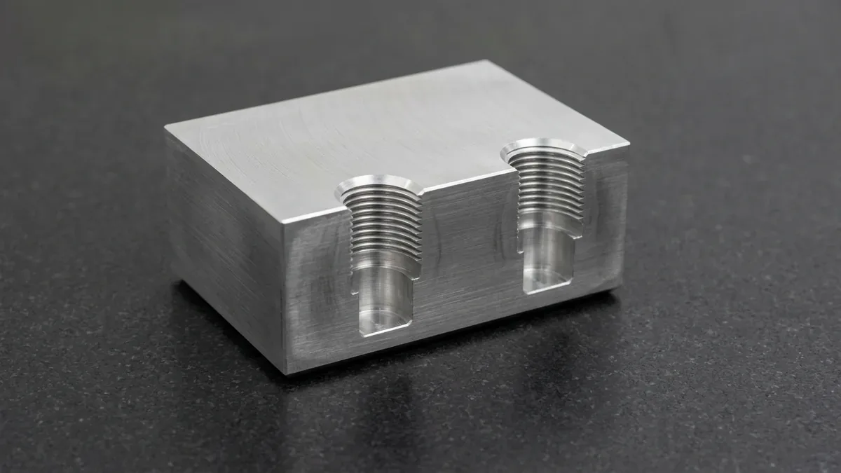
In high-value precision CNC manufacturing, generating internal and external threads is a mission-critical operation that directly dictates assembly integrity. For decades, traditional taps have been the default method for threading holes. However, as mechanical components grow in complexity—incorporating tough superalloys, delicate thin-walled housings, blind hydraulic ports, and multi-axis geometries—traditional tapping introduces severe operational risks. In precision manufacturing, mastering thread milling in cnc machining ensures repeatable dimensional stability and predictable production scaling.
A tap that seizes or fractures deep inside a finished flight-critical aerospace manifold or titanium surgical implant often results in catastrophic scrap. To eliminate this vulnerability while unlocking unparalleled dimensional control, modern precision machine shops rely on thread milling in CNC machining.
Utilizing synchronized 3-axis helical interpolation, thread milling generates burr-free, class-compliant threads with zero tap breakage risk, 0.005 mm radial pitch diameter adjustment, and full-depth blind hole threading. At AS Prototypes, thread milling is standard practice for mission-critical prototypes and production batches. Below is our complete engineering guide to thread milling principles, kinematics, tooling selection, and CNC programming best practices.
- 1. What is Thread Milling? Kinematics & Helical Interpolation
- 2. The Vital Formula: Feed Rate Compensation in Helical Milling
- 3. The 6 Decisive Advantages of Thread Milling Over Tapping
- 4. Engineering Comparison: Threading Methods Matrix
- 5. Types of Thread Milling Cutters: Choosing the Right Tool Architecture
- 6. CNC Thread Milling Best Practices & Metrology Validation
- 7. Technical Engineering FAQ
1. What is Thread Milling? Kinematics & Helical Interpolation
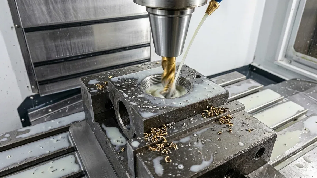
Unlike tapping—where a solid tool matches the exact thread profile and is driven directly into the hole along a single axis—thread milling is an interpolative milling process. A rotating cutting tool with a smaller diameter than the hole (dtool < Dhole) executes a synchronized helical toolpath:
- Rotational Cutting Speed (S): The thread milling cutter spins on its own center axis at high spindle speeds (typically 4,000 to 12,000+ RPM depending on cutter diameter and material).
- Circular Interpolation (X-Y Plane): The tool moves radially into the cut (via a smooth 90° or 180° arc-in roll) and traces a circular circumference matching the required thread major or minor diameter.
- Synchronized Linear Advance (Z Axis): During exactly one full 360-degree revolution in the X-Y plane, the CNC machine simultaneously advances linearly along the Z-axis by exactly one thread pitch (P).
In G-code programming on CNC machining centers, this motion is programmed using standard circular interpolation commands (G02 clockwise or G03 counter-clockwise) coupled with a simultaneous Z-axis depth increment:
Sample CNC Helical Interpolation Block (Fanuc / Haas ISO G-Code):
G03 X[Xend] Y[Yend] I[Ioffset] J[Joffset] Z[Zdepth + Pitch] F[Feedcenter]
Because the cutter diameter is smaller than the hole, cutting forces remain localized. Short, manageable chips are formed and evacuated instantly via high-pressure coolant or compressed air blast.
2. The Vital Formula: Feed Rate Compensation in Helical Milling
One of the most frequent mistakes made in thread milling programming is failing to calculate feed rate compensation at the tool center path. Standard CNC feed rates (F) are calculated based on the linear chip load per tooth at the outer peripheral cutting edge (Fcontour):
When milling an internal thread, the tool center travels along a smaller circular radius than the cutting edge on the hole circumference. If the CNC controller interprets the linear feed rate along the tool center path without compensation, the actual peripheral feed rate at the cutting edge will skyrocket—resulting in severe tool chatter, dimensional taper, or catastrophic tool snapping.
Internal Thread Milling Centerline Feed Compensation:
Fcenter = Fcontour × ((Dhole – dtool)) / (Dhole)
External Thread Milling Centerline Feed Compensation:
Fcenter = Fcontour × ((Dboss + dtool)) / (Dboss)
For example, when thread milling an internal M16×1.5 thread (Dhole = 16 mm) using a 12 mm cutter (dtool = 12 mm), the compensation factor is (16 – 12) / 16 = 0.25. The programmed tool center feed must be reduced to 25% of the nominal contour feed. Modern CAM systems automatically calculate this compensation when proper thread milling toolpath cycles are selected.
3. The 6 Decisive Advantages of Thread Milling Over Tapping
While rigid tapping remains common for high-volume mild steel stamping nuts, thread milling delivers decisive technical and economic superiority in precision CNC engineering:
1. Zero Risk of Scrapping High-Value Workpieces
When a tap breaks, its hardened flutes seize tightly inside the hole, wedged between the cut threads. Extracting a broken tap requires costly EDM spark erosion, often damaging the internal bore and causing part rejection. In contrast, a thread mill has a smaller diameter than the hole. If a thread mill ever breaks, the broken cutter falls out freely or is easily blown out with shop air, leaving the pre-drilled hole completely intact to be recut with a new tool.
2. Full-Depth Blind Hole Threading (Near-Zero Bottom Clearance)
Standard taps require a chamfered lead-in (taper, plug, or bottoming chamfer) spanning 1.5 to 4 pitches of non-functional threads, demanding substantial drilled depth clearance beyond the thread. Thread mills feature cutting teeth ground flush to the bottom face, allowing full-depth functional threads within 0.5 pitches of the hole bottom. This is indispensable in compact hydraulic valve blocks, aerospace avionics housings, and lightweight electronic enclosures.
3. Single Tool Versatility Across Multiple Diameters
A tap is restricted to a single fixed diameter and pitch (e.g., an M12×1.5 tap can only cut M12×1.5). A single thread mill of pitch P = 1.5 mm can cut M14×1.5, M16×1.5, M20×1.5, M30×1.5, and any custom diameter sharing that pitch. Furthermore, the exact same thread mill can cut both internal and external threads, and can produce right-hand or left-hand threads simply by reversing the toolpath direction.
4. Dynamic Pitch Diameter Tuning & Wear Offsets
Taps produce a fixed pitch diameter dictated by the tool grind. If plating, anodizing, or heat treatment adds thickness, a standard tap produces undersized threads that seize mating fasteners. Thread milling allows CNC operators to fine-tune the thread pitch diameter by simply entering a radial tool wear offset (Δ D) in the CNC controller, effortlessly hitting tight Class 2B/3B (UN) or 6H/4H (Metric) tolerances.
5. Superior Chip Evacuation in Difficult Materials
Taps generate long, continuous ribbon chips that tangle inside deep holes, causing tool jamming and surface galling. Thread milling produces short, comma-shaped milling chips that are cleanly flushed upward by through-spindle coolant (TSC), eliminating chip-packing failures.
6. Unsurpassed Capability in Hardened Steels & Superalloys
Tapping hardened tool steels (> 45 HRC / 450–550 HV), titanium (Ti-6Al-4V), or Inconel 718 results in immediate tap seizure due to work-hardening and immense friction torque. Solid carbide thread mills with AlTiN or TiAlN PVD coatings easily machine hardened alloys up to 62 HRC with smooth cutting dynamics and extended tool life.
4. Engineering Comparison: Threading Methods Matrix
To assist manufacturing engineers in selecting the optimal threading method, we evaluate thread milling against rigid tapping, thread turning, and thread rolling:
5. Types of Thread Milling Cutters: Choosing the Right Tool Architecture
Selecting the optimal cutter geometry balances cycle time, radial tool deflection, and thread form accuracy:
1. Solid Carbide Multi-Tooth Helical Thread Mills
Featuring full-length rows of thread form teeth ground along helical flutes, these cutters mill the entire thread depth in a single 360-degree helical revolution. This achieves the fastest possible cycle times in shallow-to-medium depth holes (L/D ≤ 2.5). The helical flute geometry smoothly distributes radial cutting forces, minimizing chatter.
2. Single-Profile (Single-Tooth) Thread Mills
Equipped with only one or two thread teeth at the cutter tip, single-profile cutters generate threads by making sequential helical passes down the bore. While cycle times are longer, cutting forces are minimal. They are indispensable for deep-reach holes (L/D > 3 × D), delicate thin-walled aerospace housings, non-standard custom pitches, and miniature micro-threads (< M1.6).
3. Indexable Insert Thread Mills
For large diameter threading (Ø > 20 mm to 150+ mm)—such as heavy equipment hydraulic ports, oilfield casing threads, and large industrial flange bolt rings—indexable insert thread mills offer the lowest cost-per-thread. Replaceable carbide inserts feature multi-tooth or single-tooth profiles that can be indexed or swapped without removing the toolholder from the spindle.
4. Tapered Pipe Thread Mills (NPT / NPTF / BSPT)
Tapered pipe threads feature a 1:16 taper (3/4 in per foot) designed to form fluid-tight mechanical seals. Conventional NPT tapping requires immense torque and frequently causes torn crests or premature leakage. Taper-ground thread mills cut NPT and NPTF Dryseal threads smoothly with precise thread depth control, eliminating cross-threading and micro-leakage in high-pressure pneumatic and hydraulic blocks.
6. CNC Thread Milling Best Practices & Metrology Validation
To ensure flawless thread quality, AS Prototypes adheres to proven shop-floor protocols:
- Climb Milling (Down-Milling) Toolpaths: Always program climb milling. For internal right-hand threads, program the tool to feed from the bottom of the hole upward (bottom-to-top) in a counter-clockwise arc (
G03). This forces chips downward out of the cutting zone and guarantees clean crests without micro-burrs. - Arc-In / Arc-Out Smooth Roll Entry: Never plunge directly into the wall. Program a tangential 90° or 180° circular roll-in arc to engage the cut smoothly, preventing dwell shock marks and tool deflection.
- Multi-Radial Pass Strategy for Hard Alloys: When thread milling hardened steels (> 45 HRC), stainless 316L, or titanium, divide the radial depth of cut into 2 or 3 passes (e.g., 65% roughing → 25% semi-finishing → 10% spring pass). A final spring pass (repeating the final path without radial offset) eliminates tool push-off taper.
- Verified Thread Metrology: Every threaded port is verified using calibrated double-ended Go/No-Go thread plug gauges (Class 2B/3B or 6H/4H). For critical aerospace connections, 2.5D optical vision measuring systems (VMS) and on-demand Zeiss CMM verification check thread flank angles (60° ±0.5°) and true position conformity.
7. Technical Engineering FAQ
Yes. As long as the thread pitch (P) is identical, a single thread milling cutter can cut any internal or external diameter. For instance, a 1.5 mm pitch metric thread mill can cut M14×1.5, M16×1.5, M20×1.5, and larger ports simply by adjusting the circular interpolation radius in the CNC program.
In circular interpolation inside a hole, the tool center path has a smaller radius and travels a shorter distance than the peripheral cutting edge contacting the workpiece. If you program the peripheral cutting feed without compensation, the actual feed at the tool center will be drastically over-driven, leading to severe chatter, tool deflection, and premature cutter breakage.
For high-volume, small-diameter, shallow holes in mild steel, rigid tapping is faster because a tap finishes the hole in a single axial stroke. However, in hard-to-machine materials, large-diameter holes, blind holes requiring near-zero bottom clearance, or high-value parts where tap breakage risks scrap, thread milling provides far greater process security, higher thread quality, and lower total manufacturing cost.
Yes. Solid micro-grain carbide thread mills featuring high-aluminum PVD coatings (such as AlTiN or TiAlN) are specifically engineered to cut threads in hardened tool steels, mold steels, and superalloys up to 62 HRC. This eliminates the need for expensive EDM thread burning or post-heat-treat thread grinding.
Because the tool path radius is smaller than the hole radius, internal thread milling feed rate must be compensated: F_center = F_contour × (D_hole – d_tool) / D_hole to prevent severe cutter overload.
Partner with Our Precision CNC Machining & Engineering Team
Eliminate tap breakage, pitch diameter binding, and blind-hole clearance bottlenecks before production begins. Upload your 3D CAD files (STEP/IGES) and 2D GD&T drawings for a comprehensive shop-floor DFM review and custom quotation.
Upload 3D CAD for Engineering DFM & RFQ