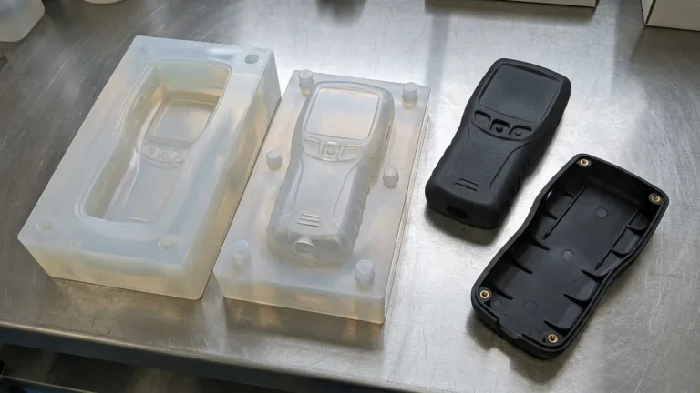
Controlling vacuum casting cost is a critical engineering objective for hardware product teams bridging the gap between functional rapid prototyping and full-scale injection molding. Polyurethane vacuum casting—frequently designated as silicone tooling or room-temperature vulcanizing (RTV) urethane molding—delivers pre-production quantities of 10 to 100 end-use parts with production-grade surface textures and authentic thermoplastic mechanical properties without the steep capital expenditures and multi-week lead times of hardened steel tooling.
However, while silicone tooling eliminates heavy upfront metal mold machining expenses, overall program budgets can quickly spiral out of control when Design for Manufacturability (DFM) principles are neglected. Key engineering factors—including master pattern finishing levels, thermal shrinkage differentials, draft angle provisions, parting line orientation, and secondary assembly steps—directly govern silicone mold longevity, per-part cycle times, and scrap rates.
At AS Prototypes, our in-house custom polyurethane vacuum casting services leverage precision master pattern machining and advanced degassing protocols to optimize unit economics. Below is a comprehensive engineering guide detailing seven actionable DFM rules to minimize vacuum casting costs across tooling fabrication, resin selection, and part geometry.
- 1. The Anatomy of Vacuum Casting Cost: Upfront Tooling vs. Consumables
- 2. Material Selection: Polyurethane Resin Formulations vs. Production Thermoplastics
- 3. Rule 1: Master Pattern Fabrication & Surface Finish Stratification
- 4. Rule 2: Incorporate Generous Draft Angles (1.0°–1.5°) & Demold Shear Kinetics
- 5. Rule 3: Maintain Uniform Nominal Wall Thickness (1.5mm–4.0mm) & Exothermic Control
- 6. Rule 4: Eliminate Complex Undercuts & Loose Silicone Cores
- 7. Rule 5: Non-Cosmetic Parting Line Routing & Flash Containment
- 8. Rule 6: Pre-Encapsulate Knurled Brass Inserts vs. Secondary Heat Staking
- 9. Rule 7: Batch Quantity Optimization & Transition Thresholds to Rapid Tooling
- 10. Shop-Floor Failure Modes, Metrology Verification & Troubleshooting
- 11. Technical Engineering FAQ
1. The Anatomy of Vacuum Casting Cost: Upfront Tooling vs. Consumables
Vacuum casting program expenditures divide into three distinct engineering cost centers: physical master model preparation, room-temperature vulcanizing (RTV) silicone mold pouring, and manual resin casting labor. Unlike CNC milling where machine spindle runtime and cutter wear dictate 70% of component cost, vacuum casting capital expenditure concentrates heavily on upfront tooling preparation, while piece-part costs scale with manual demolding, degassing cycle time, and material consumption.
To establish predictable budgeting across low-volume pre-production batches, design engineers must calculate total part unit cost using the foundational amortized tooling formula. The complete unit part cost Cpart is mathematically defined as:
Cpart = [ ( Cmaster + Nmolds · Cmold ) / Q ] + Cresin + Clabor + Cfinishing
Where Cmaster represents master model fabrication and hand-finishing expense, Cmold is the raw silicone material and degassing labor per mold box, Nmolds is the required number of duplicate silicone molds based on shot life, Q is the total batch quantity, Cresin represents metered polyurethane weight, Clabor covers vacuum chamber operations, and Cfinishing accounts for gate cutoff, parting line de-flashing, and quality inspection.
Consider an engineering evaluation batch of 20 electronic enclosures requiring one RTV silicone mold versus an expanded pilot run of 40 units requiring two duplicate molds. Because the initial master pattern cost (Cmaster) is completely amortized across the entire 40-unit program, the amortized tooling cost per part drops by 32% even when factoring in the second silicone mold pour. Hardware development teams should align their prototype verification matrix with silicone tool life increments to maximize economic efficiency.
2. Material Selection: Polyurethane Resin Formulations vs. Production Thermoplastics
Polyurethane vacuum casting resins are formulated two-component thermoset prepolymers engineered to replicate the exact mechanical, thermal, and optical properties of commercial injection-molded thermoplastics. Selecting the appropriate polyurethane formulation requires balancing tensile modulus, impact resistance, and heat deflection temperature (HDT) against resin viscosity and curing pot life.
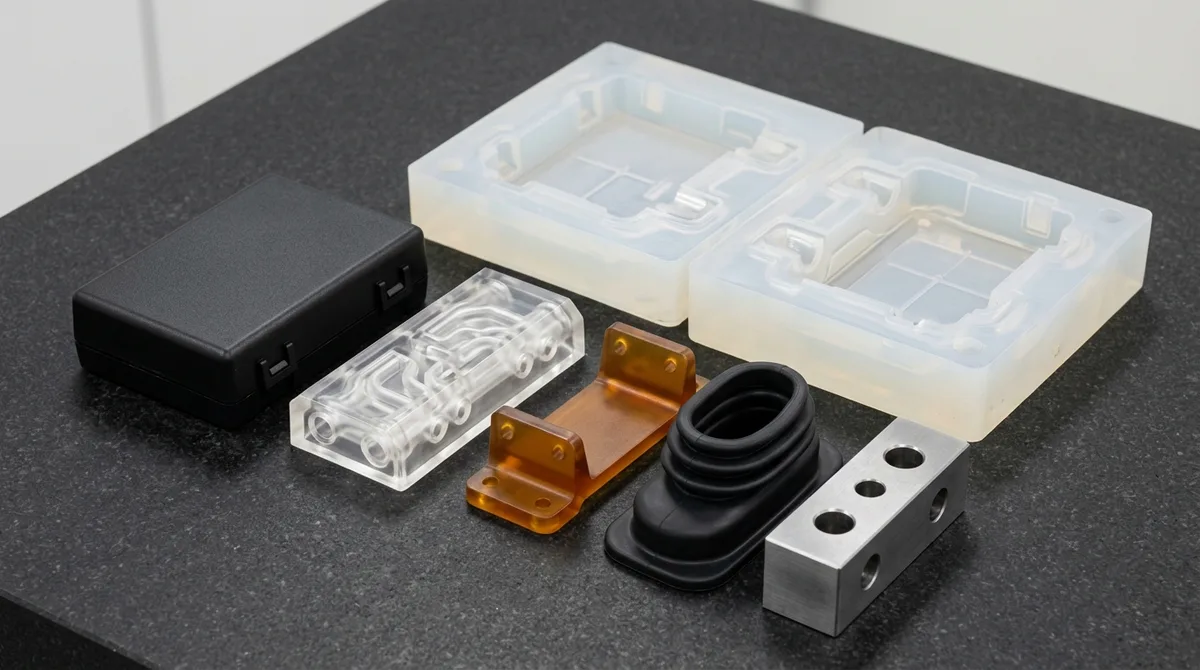
In our Shenzhen casting facility, raw test coupon specimens undergo comprehensive physical inspection to evaluate resin flow kinetics, degassing clarity, and Shore hardness stability. As demonstrated in the four comparative polyurethane resin specimens resting flat on an ESD tray below, polyurethane chemistries range from high-impact ABS-simulating formulations to optical-grade transparent urethanes and dynamic elastomeric polymers.
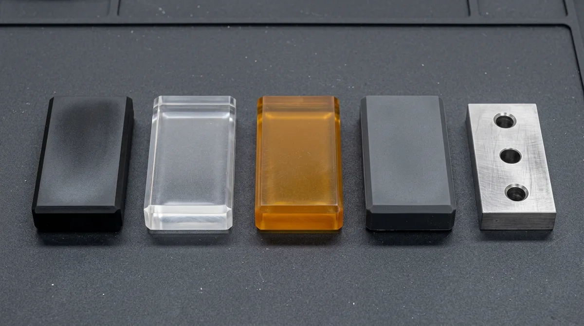
Rigid polyurethanes such as Hei-Cast 8150 and Axson 8400 accurately match injection-grade ABS and high-impact polystyrene (HIPS). These resins provide tensile strengths between 65 MPa and 75 MPa and flexural moduli exceeding 2.2 GPa, making them ideal for structural housings, automotive interior trim bezels, and mechanical enclosures. For optical applications, specialized aliphatic polyurethanes like Axson PX-5210 deliver greater than 88% luminous transmission, simulating clear polycarbonate (PC) and acrylic (PMMA) without internal yellowing or birefringence.
When applications demand thermal stability under sustained load, high-performance formulations such as SikaBiresin G26 offer heat deflection temperatures reaching 130°C to 140°C at 0.45 MPa, effectively simulating glass-filled polybutylene terephthalate (PBT) and nylon 6/6 (PA66). Conversely, elastomeric polyurethanes (Axson UR-3450 series) provide continuous Shore hardness customization from 30A to 90A, serving functional overmolding gaskets, flexible sealing boots, and vibration dampening mounts.
| Resin Formulation | Simulated Thermoplastic | Shore Hardness | Tensile Strength (MPa) | Flexural Modulus (GPa) | HDT (°C @ 0.45 MPa) | Elongation at Break (%) | Recommended Application / When to Choose |
|---|---|---|---|---|---|---|---|
| Hei-Cast 8150 / Axson 8400 | ABS / HIPS | 80D – 85D | 65 – 75 | 2.1 – 2.5 | 80 – 95 | 10 – 15% | Consumer electronics housings, snap-fit bezels, functional prototype enclosures. |
| Axson PX-5210 | Optical PMMA / Polycarbonate | 82D – 86D | 60 – 70 | 1.9 – 2.3 | 90 – 105 | 8 – 12% | Optically clear light guides, diagnostic flow cells, transparent display lenses. |
| SikaBiresin G26 | PA66-GF / PBT | 84D – 88D | 70 – 85 | 2.4 – 2.8 | 125 – 140 | 6 – 10% | Under-hood automotive brackets, thermal test fixtures, electrical switchgear. |
| Axson UR-3450 | TPE / TPU / Rubber | 40A – 85A | 15 – 30 | 0.05 – 0.2 | Ambient Elastic | 250 – 450% | Gaskets, overmolded seals, elastomeric bellows, wearable tactile touchpoints. |
3. Rule 1: Master Pattern Fabrication & Surface Finish Stratification
A physical master model forms the exact geometric baseline for every subsequent silicone mold cavity. Liquid RTV silicone rubber possesses near-molecular replication fidelity, duplicating surface topologies down to 0.1 μm Ra. Consequently, every microscopic toolpath mark, stereolithography build layer, or hand-sanding scratch present on the master pattern reproduces faithfully onto every molded polyurethane part.
A frequent driver of inflated vacuum casting cost is over-specifying cosmetic finishes across non-visible faces. Demanding an SPI A-1 optical diamond-buffed polish across internal ribs and blind mounting standoffs forces technicians to spend 8 to 15 hours manually lapping internal corners on the SLA master model. Product designers should consult our complementary analysis on 3D printed rapid tooling and master patterns to review SLA resin layer compensation and optical polishing parameters.
Engineers should partition 2D technical drawings into clearly delineated cosmetic zones:
- Class-A External Cosmetic Faces: Specify targeted hand finishing, such as SPI A-2 high gloss, SPI B-1 medium paper polish, or SPI C-1 stone texture on primary user-facing covers.
- Class-B Semi-Cosmetic Surfaces: Specify a uniform fine bead blast (VDI 24 to VDI 27 satin equivalent), which conceals 0.05 mm SLA build steps without labor-intensive manual paper lapping.
- Class-C Internal Non-Cosmetic Walls: Specify as-built SLA or CNC milled finishes with clean 0.2 mm edge deburring. Permitting minor layer striations on internal ribs cuts master pattern production lead time by 40% and reduces initial tooling expense.
4. Rule 2: Incorporate Generous Draft Angles (1.0°–1.5°) & Demold Shear Kinetics
Applying a nominal draft angle of 1.0° to 1.5° on vertical cavity sidewalls reduces demolding shear stress on silicone mold rubber by over 40%, extending production mold life from 12 shots to 25 shots. While flexible silicone molds can theoretically tolerate zero-draft faces due to rubber elasticity, stripping parts with zero draft generates severe interfacial shear friction against silicone cell walls.
During demolding, the interfacial frictional shear stress τdemold(z) acting on the flexible silicone cavity wall as the part is vertically extracted by distance z along the draw direction is governed by contact mechanics:
τdemold(z) = μ · Esilicone · [ max( 0, ΔL0 – z · tan(θ) ) / h ]
Where μ is the dynamic coefficient of friction between cured polyurethane and cured silicone, Esilicone is silicone tensile modulus (~1.2 to 1.8 MPa), ΔL0 is the initial radial interference caused by volumetric cure shrinkage clamping the mold, h is flexible silicone wall thickness, and θ is the draft angle.
For a typical initial shrinkage interference of ΔL0 = 0.03 mm, incorporating a 1.5° draft causes the silicone wall to detach completely from the part after only z = 0.03 / tan(1.5°) ≈ 1.15 mm of initial vertical stroke. Beyond 1.15 mm, interfacial shear stress drops to zero for the remaining draw stroke.
Conversely, with zero draft (θ = 0°), full normal pressure and rubbing friction persist across the entire 30 mm draw depth, accelerating silicone tearing.
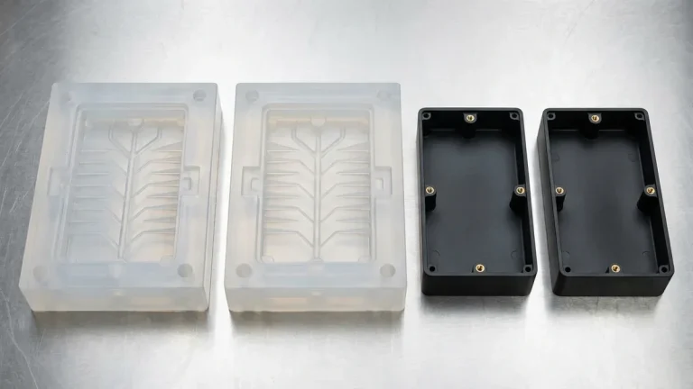
The visual relationship between master pattern draft angles and silicone mold cavity preservation is demonstrated in the open two-piece RTV silicone mold resting flat on the assembly bench below. Notice the clean 1.5-degree draft taper on the interior rib slots and the engineered perimeter parting split line designed for low-friction extraction.
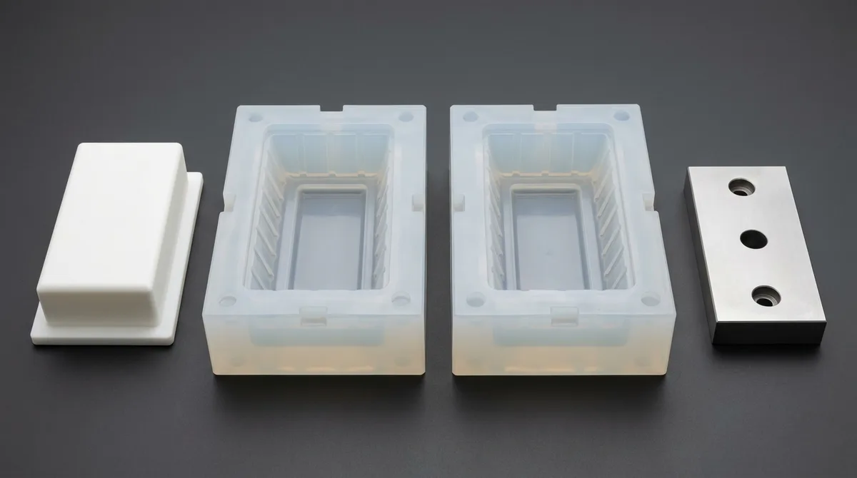
By incorporating a 1.0° to 1.5° draft on all outer cosmetic walls and deep reinforcing ribs, the silicone mold separates instantaneously from the curing polyurethane part upon initial mold opening. This rapid relief eliminates sustained rubbing, preserves sharp corner definitions, and prevents premature tool replacement.
5. Rule 3: Maintain Uniform Nominal Wall Thickness (1.5mm–4.0mm) & Exothermic Control
Maintaining uniform nominal wall thickness between 1.5 mm and 4.0 mm across the component prevents localized exothermic scorching of the silicone mold cavity and eliminates volumetric shrinkage defects. Polyurethane resins cure via an exothermic polyaddition chemical reaction between polyols and isocyanates. Inside a thermally insulating silicone mold, thick solid masses generate concentrated core temperature spikes exceeding 120°C.
The total volumetric shrinkage Stotal experienced during polyurethane casting combines polymer chemical cure shrinkage with differential thermal expansion between the resin and the silicone flask:
Stotal = Spoly + αresin · ( Tpeak – Tambient ) – αsilicone · ( Tcure – Tambient )
Where Spoly represents intrinsic chemical cure shrinkage (typically 0.15% to 0.30%), αresin is the resin thermal expansion coefficient (~80 × 10⁻⁶ / K), αsilicone is silicone rubber thermal expansion (~300 × 10⁻⁶ / K), Tpeak is the internal exothermic core temperature, and Tcure is the convection oven stabilization temperature (65°C to 70°C).
Because silicone expands thermally at elevated oven temperatures (αsilicone ≈ 300 × 10⁻⁶ / K), uniform 2.0 mm walls cure isothermally, balancing chemical contraction against thermal relaxation. In contrast, thick 8.0 mm solid bosses create localized thermal runaway exceeding 120°C, triggering severe differential contraction and deep sink marks.
To maintain structural stiffness without adding excessive wall thickness, apply coring to thick sections and incorporate support ribs adhering to strict injection-molding DFM guidelines. Rib base thickness should not exceed 50% to 60% of the nominal adjoining wall thickness, with a maximum rib height of 3× nominal wall thickness and a minimum 0.5 mm root radius. This geometry ensures rapid, uniform thermal dissipation, minimizes cycle times in the post-cure oven, and protects the silicone mold from localized thermal degradation.
6. Rule 4: Eliminate Complex Undercuts & Loose Silicone Cores
Eliminating severe internal undercuts and deep blind re-entrant angles reduces manual labor per cast part by 25% to 35% by avoiding multi-piece silicone inserts and loose core pick-outs. While silicone rubber flexibility allows demolding around mild external undercuts, deep internal features cannot be stripped in a standard two-piece mold pull without tearing the tool.
When undercuts are unavoidable, mold technicians must fabricate separate loose silicone cores or rigid aluminum inserts that are manually placed into the mold before pouring and stripped from each cured part after demolding. This manual handling introduces witness lines, increases cycle time, and introduces positional tolerance stack-ups up to ±0.25 mm. Product designers can eliminate loose cores through three primary DFM design strategies:
- Pass-Through Coring Windows: For snap-fit hooks and internal latches, incorporate an access aperture directly beneath the cantilever hook. This enables straight-pull mold separation where a core shutoff forms the latch shelf without requiring side-action inserts.
- External Feature Reorientation: Orient exterior bosses, cable pass-throughs, and mounting brackets parallel to the primary mold draw direction.
- Modular Multi-Part Splitting: For complex manifolds with multi-axis internal channels, split the geometry into two solvent-bonded or mechanically fastened sub-housings. Casting two simple, fast-demolding components often costs significantly less than casting a single complex assembly requiring multi-segment silicone cores.
7. Rule 5: Non-Cosmetic Parting Line Routing & Flash Containment
Routing the silicone mold parting line along natural component feature edges, bottom chamfers, or hidden gasket tracks reduces post-processing de-flashing labor to rapid scalpel trimming. To extract the master pattern from the cured silicone block, mold makers manually cut the mold along a pre-planned split line using a scalpel. Wherever liquid polyurethane enters this seam under vacuum, micro-flash inevitably forms.
If the parting line cuts arbitrarily across a smooth Class-A cosmetic face, every cast part requires manual blade trimming, sequential wet sanding (#400 to #1500 grit), and post-spray painting to conceal witness lines. This manual refinishing can double the piece-part labor cost. By contrast, designing a continuous 0.5 mm × 45° perimeter chamfer or a 1.0 mm perimeter step around the housing base creates a natural knife-guide groove. Flash formed within this recess is severed cleanly in seconds with a deburring blade, leaving visible surfaces untouched.
8. Rule 6: Pre-Encapsulate Knurled Brass Inserts vs. Secondary Heat Staking
Pre-encapsulating knurled brass threaded inserts directly into the silicone mold prior to polyurethane pouring increases joint pull-out strength by 35% while eliminating secondary ultrasonic heat-staking fixtures. Cast polyurethane resins lack the shear strength of metallic threads and cannot support repeated fastener torque cycles without thread stripping.
As illustrated in the precision-cast polyurethane enclosure resting flat on the granite plate below, circular knurled brass inserts are pre-mounted directly onto precision silicone core pins before the mold is sealed. During the casting cycle, degassed polyurethane flows into the diamond knurls, forming a permanent mechanical interlock upon thermal curing.
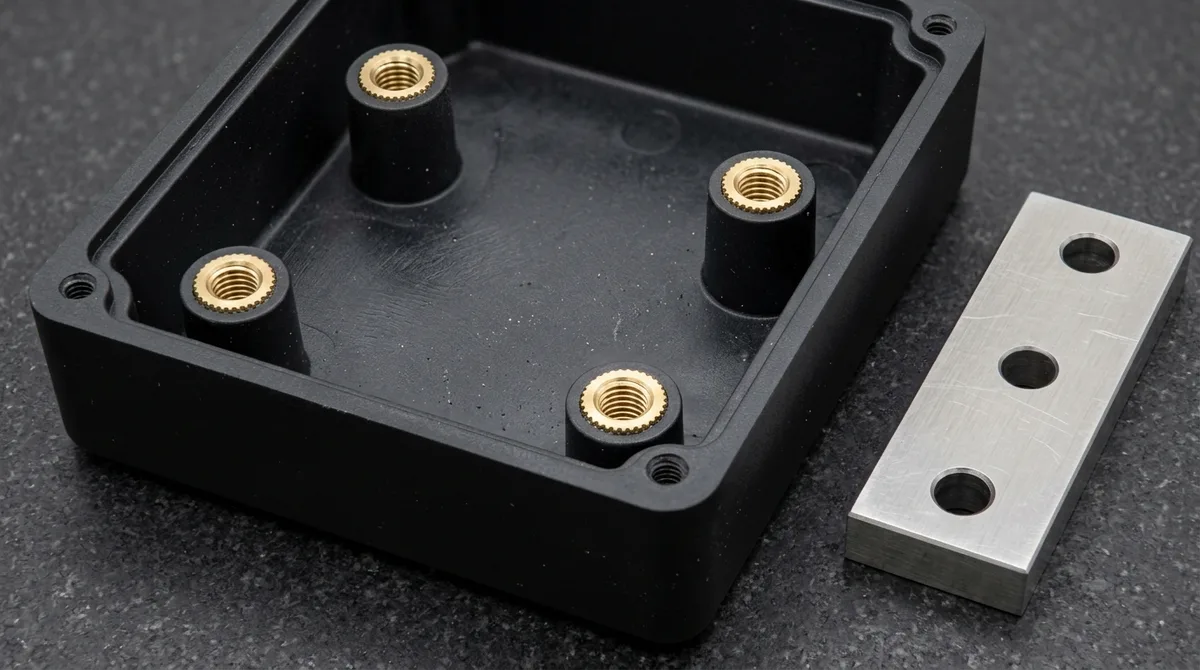
The ultimate axial pull-out resistance Fpullout of an encapsulated knurled insert is governed by insert diameter Dinsert, effective knurl engagement length Leffective, and resin shear yield strength τpolyurethane:
Fpullout = π · Dinsert · Leffective · τpolyurethane
For a standard M3 knurled brass insert (outer diameter Dinsert = 4.5 mm, effective knurl length Leffective = 5.0 mm) pre-encapsulated in rigid polyurethane with a shear yield strength τpolyurethane ≈ 35 MPa (35 N/mm²), the theoretical pull-out capacity reaches:
Fpullout = π × 4.5 mm × 5.0 mm × 35 N/mm² ≈ 2,474 N (≈ 252 kgf)
Because polyurethane resins are thermosets that do not melt upon reheating, conventional thermal heat staking often causes localized micro-cracking and erratic retention below 800 N. Pre-encapsulation eliminates secondary assembly fixtures, ensures perpendicular thread alignment within ±0.05 mm, and prevents resin intrusion by sealing the insert bottom against precision silicone locating pilots.
9. Rule 7: Batch Quantity Optimization & Transition Thresholds to Rapid Tooling
Selecting the optimal production technology requires analyzing total program volume against tooling lead times and unit part cost crossover curves. Polyurethane vacuum casting occupies an economic sweet spot between 10 and 100 units. Below 10 units, high-speed 3-axis CNC milling or industrial SLA/SLS 3D printing often delivers faster turnaround with zero tooling expenditure.
Conversely, when project demand exceeds 100 to 250 units, the recurring expense of fabricating 5 to 10 duplicate silicone molds converges with the cost of rapid aluminum tooling for rapid tooling injection molding. Aluminum injection molds (typically 7075-T651 or P20 steel tooling) require higher initial tooling investment but deliver unit cycle times under 60 seconds and support production runs of 1,000 to 10,000+ parts.
| Manufacturing Process | Upfront Tooling Investment | First Article Lead Time | Unit Part Cost Profile | Geometric Complexity & Undercuts | Surface Finish As-Cast/Milled | Recommended Production Sweet Spot |
|---|---|---|---|---|---|---|
| Precision CNC Machining | Near Zero (CAM Programming & Soft Jaws) | 4 – 8 Business Days | High (Constant Runtime Driven) | Moderate (Limited by Tool Deflection & Flute Access) | Ra 0.8 – 1.6 μm (Machined Toolpaths) | 1 – 10 units requiring true engineering thermoplastics or tight ±0.02 mm tolerances. |
| Polyurethane Vacuum Casting | Low / Moderate (SLA Master & RTV Silicone) | 7 – 12 Business Days | Moderate (Amortized Across 15–25 Shots) | High (Silicone Elasticity Permits Minor Undercuts) | Exact Replica of Master (SPI A-2 Gloss to VDI Texture) | 10 – 100 units for clinical trials, user testing, pre-series market validation. |
| Rapid Tooling Injection Molding | Substantial (7075-T6 Aluminum / P20 MUD Inserts) | 18 – 35 Business Days | Extremely Low (High-Speed Cycle Economics) | Strict (Requires Side-Actions & Complex Lifters) | SPI Standard Finishes via Cavity EDM / Polishing | 250 – 10,000+ units bridging prototype evaluation to sustained mass production. |
10. Shop-Floor Failure Modes, Metrology Verification & Troubleshooting
Rigorous metrology verification on a Zeiss coordinate measuring machine (CMM, available upon request for rigid functional housings) and 2.5D optical vision measuring systems (VMS) ensures that post-curing volumetric shrinkage aligns with master pattern CAD pre-compensation factors. In our temperature-controlled inspection lab (20°C ± 1°C), vacuum cast housings undergo multi-point dimensional verification to check Datum A flatness and hole-to-hole true position.
As captured in the metrology inspection photograph below, a coordinate measuring machine equipped with a spherical ruby ball stylus touches the top Datum A mounting plane in 360-degree open clearance, confirming that the polyurethane enclosure remains flat and warp-free after thermal post-curing.
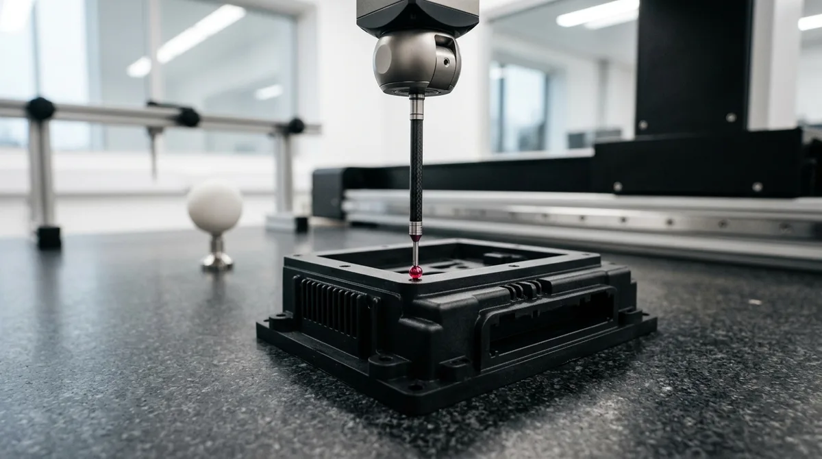
Despite strict process control, shop-floor defects can emerge during casting. Below are three representative failure modes, their underlying root causes, and corrective shop-floor actions:
- Defect: Exothermic Mold Scorch and Cavity Wall Tearing
- Symptom: Silicone mold cavity turns brittle, discolored, and tears at rib roots after 8 to 10 shots.
- Root Cause: Thick internal sections (>5.0 mm) generated localized exothermic temperatures exceeding 120°C, accelerating chemical attack from resin isocyanate groups against silicone cross-links.
- Corrective Action: Core out thick solid bosses to uniform 2.5 mm wall thickness, incorporate 1.5° draft, and implement a stepped convection post-curing profile (ramp from 45°C to 65°C over 120 minutes) to dissipate exothermic energy.
- Defect: Micro-Void Bubble Entrapment in Optical Flow Manifolds
- Symptom: Microscopic air bubbles suspended in thick fluid channels of clear PX-5210 polyurethane components.
- Root Cause: Insufficient vacuum depth (<0.5 mbar) during automated resin decanting, combined with aggressive pour velocities trapping secondary air pockets in blind pocket corners.
- Corrective Action: Extend chamber degas cycle to 180 seconds under 0.2 mbar vacuum, install secondary copper capillary riser vents at the highest geometry points, and reduce resin decanting flow rate.
- Defect: Knurled Insert Resin Intrusion & Stripped Threads
- Symptom: Polyurethane resin creeps into internal M3 threads, preventing screw engagement during final hardware assembly.
- Root Cause: Loose locating pins allowed liquid polyurethane to migrate past the bottom chamfer of the brass insert under vacuum differential.
- Corrective Action: Redesign silicone core locator pins with elastomeric sealing shoulder caps that compress against the insert face during mold closure, completely sealing the threaded bore.
11. Technical Engineering FAQ
Silicone mold tooling typically accounts for 40% to 55% of upfront expenditure, master model preparation represents 20% to 30%, and polyurethane piece-part consumables and manual labor make up the remaining 25% to 35%. Because tooling costs amortize rapidly across 15 to 25 shots, ordering quantities near mold lifespan limits significantly reduces per-unit costs.
A single RTV silicone mold reliably yields 15 to 25 parts before exothermic heat and chemical degradation affect surface quality and dimensional accuracy. Incorporating generous 1.5° draft angles, maintaining uniform wall thicknesses under 3.5 mm, and selecting non-aggressive polyurethane resins can extend mold life up to 30 shots per cavity.
Yes, advanced polyurethane formulations accurately replicate engineering thermoplastics, achieving tensile strengths from 65 to 85 MPa and heat deflection temperatures up to 140°C. Polyurethanes simulate production ABS, polycarbonate, glass-filled nylon, and elastomeric TPEs, making them fully viable for functional prototyping and regulatory clinical testing.
Standard polyurethane vacuum casting achieves typical dimensional tolerances of ±0.15 mm for spans up to 100 mm (or ±0.2% on larger dimensions). Critical features can achieve tighter tolerances by pre-compensating master pattern CAD dimensions for polyurethane volumetric cure shrinkage (typically 0.15% to 0.30%).
The economic transition typically occurs between 100 and 250 units. Beyond 100 parts, the cost of pouring 5 to 10 duplicate silicone molds converges with the capital investment of rapid aluminum tooling. Aluminum injection molds deliver cycle times under 60 seconds and cost-effectively support production batches from 250 to over 10,000 units.
Optimize Your Polyurethane Vacuum Casting & Silicone Tooling Budget
Maximize RTV silicone mold life, eliminate exothermic shrinkage defects, and reduce unit part costs with our in-house vacuum casting and rapid tooling engineering team. Upload your 3D CAD models (STEP/IGES) for a comprehensive DFM manufacturability assessment and custom quotation.
Upload 3D CAD for Vacuum Casting DFM & RFQ