Headlight light guides are solid optical polymer rods that carry LED light by Total Internal Reflection (TIR) and emit it along a styled contour for daytime running lights (DRL), sequential turn signals, and signature lighting. Prototype guides must keep luminance uniform without visible LED hotspots or dark zones, which demands optical-grade PMMA or polycarbonate (PC), polished surfaces, and stress-free parts built in our in-house automotive lighting prototyping machine shop.
⏱️ Estimated Reading Time: ~8 mins | Target Audience: Mechanical Design Engineers, R&D PMs, Sourcing Specialists
Written by: AS Prototypes Precision Engineering Team | Technically Reviewed by: Tooling & Optical Machining Specialist (12+ Years Shop-Floor Experience)
- Critical angle: 42.1° for PMMA (n ≈ 1.492) and 39.1° for PC (n ≈ 1.586).
- Bend design rule: inner radius ≥ 3.0 × thickness for PMMA, ≥ 2.5 × thickness for PC.
- Surface and tolerance: Ra ≤ 0.05 µm (2 µin) off the tool; profile ±0.010 mm (±0.0004″).
- Lead time: 7 ~ 12 Business Days for milled and polished guides, 18 ~ 35 Business Days for rapid tooling with T1 samples (Ex-Factory Production & Inspection Turnaround, separate from 3 ~ 5 Days DHL/FedEx air transit); DFM feedback Within 24 Hours.
How Does Total Internal Reflection Guide Light Through a Headlight Light Guide?
Total Internal Reflection (TIR) traps light inside a polymer guide whenever the angle of incidence exceeds the critical angle θc = arcsin(1 / n): 42.1° for PMMA (n ≈ 1.492) and 39.1° for polycarbonate (n ≈ 1.586). Bends tighter than the geometric limit leak light, so the inner bend radius must be fixed before CAD release.
Critical angle and bend limit:
θc = arcsin(1 / n) | Rinner / d ≥ 1 / (n − 1)
Take an 8 mm (0.31″) thick guide. The geometric limit is Rinner / d ≥ 1 / 0.492 = 2.03 for PMMA, or 16.3 mm, and 1 / 0.586 = 1.71 for PC, or 13.7 mm. Production rules add margin for off-axis LED rays: R / d ≥ 3.0 for PMMA (24 mm / 0.94″) and R / d ≥ 2.5 for PC (20 mm / 0.79″).
Guiding light is only half the task, because the guide must also decouple light toward the forward field of view. Micro-optical extraction structures along the rear or flank locally change the surface normal and break TIR in a controlled way:
- Precision sawtooth prisms: facets angled at 40° ~ 45° reflect light toward the emission window, with depth and pitch modulated along the length to offset attenuation.
- Negative cylindrical flutes: micro-grooves scatter light across a wider viewing angle for homogeneous DRL ribbons.
- Micro-textured dot matrices: etched patterns tuned in ray-tracing software (SPEOS, LucidShape) to balance local extraction density.
- Collimation entrance optics: compound parabolic concentrators (CPC) on the incoupling face cut Fresnel losses and align the LED cone inside the TIR acceptance angle.
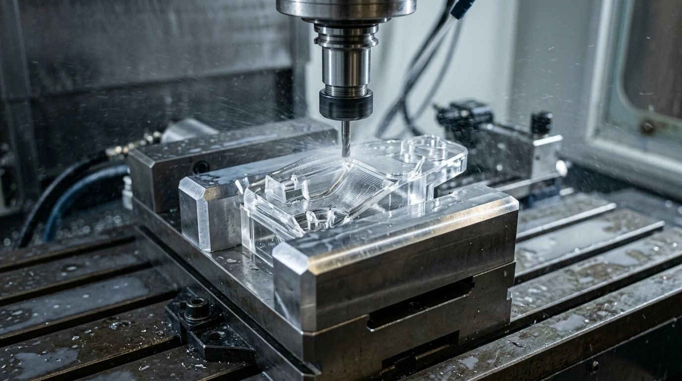
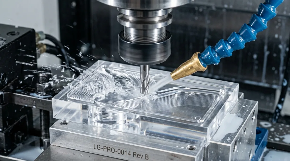
The micro-milling setup below shows a single-flute polished cutter finishing an optical PMMA light guide while a cold-air vortex gun clears chips, so the cutting zone stays dry and the surface stays free of melt smear and tool chatter marks that would scatter guided light.
Which Material Is Best for Automotive Light Guides: PMMA, PC, or PU Resin?
Cell-cast optical PMMA is the benchmark light guide material, with an Abbe number of ≈ 57 and 91 ~ 93% transmission, while optical PC is specified where the guide entrance sits within 15 mm (0.59″) of high-power LEDs and operating temperature exceeds 110 °C (230 °F). Chromatic fringing along 300 ~ 800 mm (12 ~ 31″) ribbons stays negligible in PMMA.
| Property | Cell-Cast PMMA | Optical PC | Optical PU Resin (Vacuum Casting) | Recommended Application / When to Choose |
|---|---|---|---|---|
| Refractive Index (nd) | 1.492 | 1.586 | ≈ 1.50 (grade-dependent) | Choose PC when tight packaging demands a smaller critical angle |
| Light Transmission (%) | 91 ~ 93 | 88 ~ 90 | ≈ 88 | Choose PMMA for long DRL ribbons where efficiency dominates |
| Continuous Service Temp. (°C / °F) | ≈ 85 (185 °F) | ≈ 115 (239 °F) | ≈ 60 ~ 80 (140 ~ 176 °F) | Choose PC when the entrance faces sit within 15 mm (0.59″) of LED arrays |
| Prototype Route | Diamond micro-milling | Diamond micro-milling or rapid tooling | Vacuum casting from polished master | Choose PU casting only for styling reviews, not photometric validation |
When to avoid: skip PMMA beside heat sources above 85 °C (185 °F), where creep distorts the incoupling face. Skip PU resin for any vehicle test or photometric release, and keep unannealed PC away from solvent-based cleaners, which cause environmental stress cracking. For the lens, reflector, and housing around a guide in a full headlamp, see our guide to automotive headlamp prototype materials.
Prototyping Technologies: Diamond Micro-Milling vs Rapid Tooling vs Vacuum Casting
Optical-grade smoothness of Ra ≤ 0.05 µm (2 µin) on swept 3D splines is where general shops stumble. Three routes cover the program stages: direct diamond micro-milling for bench samples, rapid optical tooling for pre-series volumes, and vacuum casting for styling models.
Diamond Micro-Milling (5-Axis for Swept Freeform Splines)
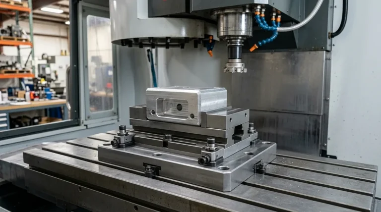
Diamond micro-milling is a subtractive process in which monocrystalline diamond (MCD) ball-nose end mills cut optical polymer at 30,000 ~ 50,000 RPM, holding profile tolerance of ±0.010 mm (±0.0004″) and Ra ≤ 0.05 µm (2 µin) before polishing. Guides that tilt through compound angles need simultaneous 5-axis motion; planar-curved guides run on 3-axis and 4-axis centers.
Typical parameters use Ø1.0 ~ 2.0 mm MCD ball tools at fz ≈ 0.002 ~ 0.005 mm/tooth, giving Vc ≈ 94 ~ 314 m/min across that speed range. In our Shenzhen machine shop practice, we cut extraction prisms in a dedicated finishing pass with a fresh MCD edge, because chatter marks on prism flanks scatter light and appear as bright streaks.
Rapid Optical Tooling and Pre-Series Injection Molding
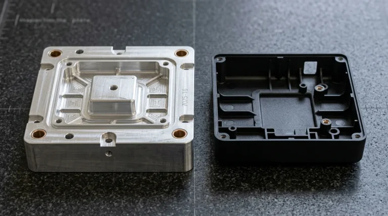
Rapid optical tooling uses CNC-machined 7075-T6 aluminum or pre-hardened NAK80 and Stavax ESR inserts, mirror-polished to SPI A-1 (Ra ≈ 0.012 µm / 0.5 µin), to mold 50 ~ 1,000 functional light guides with production-like molecular orientation. Sections thicker than 6 mm (0.24″) risk sink marks and knit lines, so packing pressure and gate freeze-off time need DFM review.
Vacuum Casting with Optical Clear Polyurethanes
Vacuum casting pours two-component optical PU resin (such as Axson PX 5210) into a platinum-cured silicone mold at below 1 mbar, producing bubble-free guides with ≈ 88% light transmission for styling reviews and show models. A diamond-milled, polished master drives the surface quality, and finished sets ship in 7 ~ 12 Business Days Ex-Factory Production & Inspection Turnaround.
Precision Optical Finishing: Diamond Lapping, Vapor Polishing, and Annealing
Surface roughness decides whether photons reflect cleanly by TIR or scatter into the lamp bezel, so finishing is where light guides pass or fail photometric inspection. Machining and polishing also leave shear stress in the polymer, which shows as photoelastic rainbow fringes (birefringence) under polarized light and causes local light leakage and haze.
- Step 1: Progressive Diamond Lapping – Wet-sand with 1200-grit micro-mesh and deionized water, then polish with 6, 3, and 1 µm monocrystalline diamond paste on felt bobs and wool pads below 1,200 RPM, finishing with 0.25 µm cerium oxide slurry.
- Step 2: Solvent Vapor Polish (PC Only) – Reflow the outer 2 ~ 4 µm of intricate PC geometry with controlled vapor exposure; excessive dwell rounds prism crests and shifts the extraction angle.
- Step 3: Stress-Relief Annealing – PMMA: ramp 10 °C/h to 85 °C (185 °F), soak 1 h per 5 mm of thickness, cool at ≤ 8 °C/h to 40 °C. PC: ramp 15 °C/h to 120 °C (248 °F), soak 2 h, cool at ≤ 10 °C/h.
Troubleshooting: Bright Streaks and Rainbow Fringes
- Symptom: Bright streaks run along the guide flank when lit.
- Root Cause: Tool chatter marks or worn diamond edge on prism flanks scatter light out of the guide.
- Corrective Action: Re-run the finishing pass with a fresh MCD edge, add chatter suppression through reduced stick-out, and re-lap with 1 µm paste.
- Symptom: Rainbow fringes under a polarizer and leakage near bends.
- Root Cause: Residual stress from machining or vapor polishing shifts local refractive index.
- Corrective Action: Anneal per the cycles above, then re-inspect between crossed polarizers before photometric release.
Photometric Validation: Which Standards Apply to Light Guide Prototypes?
Light guide prototypes are measured against ECE R87 for daytime running lamps, ECE R148 for light-signalling devices, SAE J1383, and FMVSS 108, using goniophotometer intensity maps, imaging colorimeter luminance maps with Lmin / Lmax ≥ 0.85, and CIE 1931 chromaticity checks. Clear 3D printed guides fail this stage because layer interfaces scatter light.
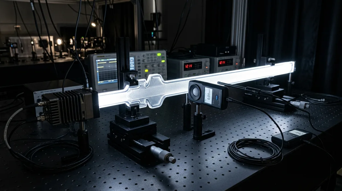
The bench setup below evaluates luminance uniformity and extraction efficiency of a prototype light guide; a two-dimensional imaging colorimeter maps Lmin / Lmax across the emission window, and the guide is released to OEM styling review only once the map reaches ≥ 0.85.
- Goniophotometer intensity distribution: a dark-room goniophotometer records candela across horizontal and vertical angles and exports standard IES / LDT files.
- Luminance uniformity mapping: a CCD imaging colorimeter measures the whole emission surface; Lmin / Lmax ≥ 0.85 gives a seamless ribbon.
- Chromaticity analysis: an integrating sphere verifies flux transmission and keeps CIE 1931 (x, y) inside white or amber boundaries without yellowing drift.
Lab measurement of a prototype does not replace regulatory type-approval, which requires production-intent tooling and durability data. Build the prototype to validate the optical design, not to claim legal compliance.
Engineering Recommendation: Which Route Fits Your Program?
- Early bench validation: choose diamond micro-milling in PMMA, then polish and anneal.
- Heat-exposed entrance faces: choose optical PC and verify with a thermal soak.
- 50 ~ 1,000 functional units: choose rapid optical tooling with SPI A-1 cavities.
- Styling review only: choose PU vacuum casting from a polished master.
Frequently Asked Questions
Keep the inner bend radius at R / d ≥ 3.0 for PMMA and R / d ≥ 2.5 for PC, because the geometric limit of 1 / (n − 1) is only 2.03 and 1.71 and off-axis LED rays need margin. When packaging forces tighter bends, specify higher-index PC, metallize the outer curve with vacuum-deposited aluminum, or add reflective white backing.
Machining and polishing leave residual stress that causes birefringence, so the polymer shows two refractive indices depending on polarization. That distorts ray paths and creates dark patches and haze. Annealing at 85 °C for PMMA or 120 °C for PC relaxes frozen-in stress, restores uniform index, and prevents solvent-induced crazing.
No, clear SLA and PolyJet guides cannot pass functional photometric validation. Layer interfaces scatter light, transmission drops to 80 ~ 85%, and photopolymers yellow under UV. They suit packaging and harness fitment checks only. Functional testing needs diamond-milled PMMA or PC guides, or SPI A-1 rapid tooling parts.
Accelerate Your Automotive Lighting Prototyping
Developing daytime running lights, animated taillamp light guides, or headlamp optical demonstrators? Transitioning from rapid prototypes to low-volume pilot production? Upload your 3D CAD files (STEP/IGES) to evaluate tooling setups and optimize unit manufacturing costs.