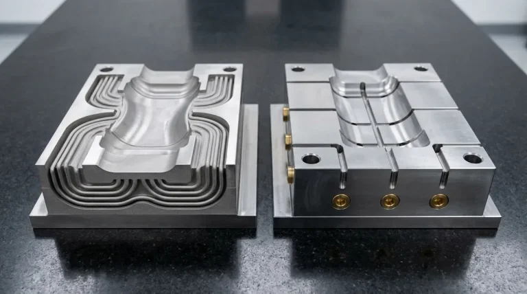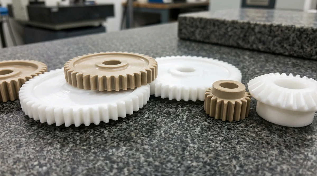
Low-volume plastic injection molding represents the vital bridge between initial prototyping and full-scale mass manufacturing, enabling hardware innovators to produce 100 to 10,000+ end-use parts without committing to expensive multi-cavity steel tooling. In modern agile hardware development, low-volume production accelerates market launch, mitigates inventory risk, and satisfies strict regulatory pilot evaluations. In our in-house injection molding and tooling facility, combining rapid aluminum tooling, modular Master Unit Die (MUD) frames, and strict DFM disciplines reduces upfront tooling expenditure by up to 60%.
- Core Focus & DFM Scope: Actionable shop-floor engineering guidelines for Low-Volume Plastic Injection Molding, covering material selection, geometric tolerancing, and defect prevention.
- Dimensional Tolerance Baseline: General molded/cast features hold ISO 2768-mK or ±0.05 to ±0.10 mm (±0.002″ to ±0.004″); critical post-machined datum bores achieve ±0.010 mm (±0.0004″).
- Tooling & Surface Integrity: Cavity surfaces finished from SPI A-2 mirror polish (Ra 0.05 µm / 2 µin) to VDI 3400 spark-eroded textures with mandatory 1.0°–2.5° draft angle compensation.
- Metrology & Flow Validation: Pre-tooling DFM and rheological fill simulation paired with Zeiss CMM first-article inspection (FAI) and wall-thickness ultrasonic/section verification.
- Ex-Factory Turnaround: 7 to 12 business days for vacuum cast/urethane bridge batches; 18 to 35 business days for rapid aluminum/P20/H13 tooling and T1 sample delivery (excluding 3–5 days air transit).
1. Tooling Strategies for Low-Volume Production: Aluminum vs. Pre-Hardened Steel
The core economic driver in low-volume injection molding is matching the mold substrate to the required production volume, resin abrasiveness, and surface cosmetic finish:
- Rapid QC-10 / 7075-T651 Aluminum Tooling: Aerospace-grade aluminum delivers thermal conductivity roughly 4× to 5× higher than tool steel (130 W/m·K vs. 29 W/m·K). This superior heat dissipation cuts molding cooling cycles by 30% to 50%, while high-speed CNC milling produces polished mold cavities in 18 to 35 business days. Ideal for production runs between 100 and 5,000 shots.
- Pre-Hardened P20 / NAK80 Steel Tooling: Offering core hardness between 30 and 40 HRC, pre-hardened steels eliminate the need for post-machining heat treatment. They provide exceptional resistance to abrasive glass-filled resins (such as PA66-GF30) and allow production volumes up to 25,000 to 50,000 shots.
- Master Unit Die (MUD) Insert Systems: Rather than machining an entirely new mold base, custom core and cavity inserts are installed into universal, pre-plumbed master mold frames. This strategy eliminates base plate fabrication costs and cuts mold lead times in half.
| Tooling Material | Tool Hardness | Thermal Conductivity | Tool Life Expectancy | Typical Tooling Lead Time | Optimal Production Volume |
|---|---|---|---|---|---|
| 7075-T651 Aluminum | 150 HB | 130 W/m·K | 5,000 – 10,000 shots | 18 – 25 Business Days | 100 – 2,500 parts |
| P20 Pre-hard Steel | 30 – 34 HRC | 29 W/m·K | 25,000 – 50,000 shots | 20 – 28 Business Days | 1,000 – 20,000 parts |
| NAK80 Mirror Steel | 37 – 43 HRC | 41 W/m·K | 50,000 – 100,000 shots | 22 – 30 Business Days | Optical lenses, SPI A-1 high-gloss |
| S136 Stainless Steel | 48 – 52 HRC | 18 W/m·K | 100,000+ shots | 18 – 25 Business Days | Corrosive resins (PVC, POM, flame retardants) |
2. Low-Volume Molding vs. Polyurethane Vacuum Casting
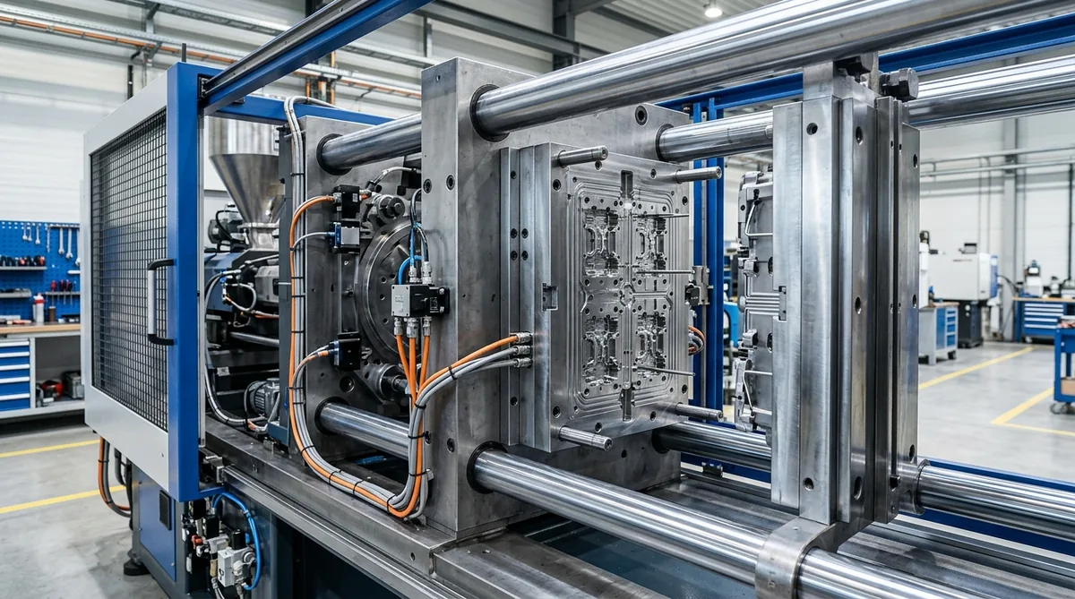
Engineers evaluating low-volume manufacturing frequently weigh rapid injection molding against silicone-tooled vacuum casting. The selection hinges on production volume, material grade selection, and per-unit budget:
| Comparison Parameter | Polyurethane Vacuum Casting | Low-Volume Rapid Injection Molding |
|---|---|---|
| Tooling Investment | Very Low (Rapid 3D Printed / Master Pattern Tooling) | Moderate (Aluminum Prototype Cavity Tooling) |
| Part Unit Cost | Moderate (Short-Run Polyurethane Casting) | Low (High-Efficiency Thermoplastic Injection) |
| Mold Life Span | 15 – 25 parts per silicone tool | 5,000 – 50,000 parts |
| Material Authenticity | Thermoset Polyurethanes (Simulated) | 100% Production Thermoplastics (ABS, PC, Nylon) |
| Cycle Time per Part | 3 – 4 Hours (Oven cure) | 15 – 45 Seconds per shot |
| Economic Crossover Point | Best for 1 – 50 units | Best for 50 – 10,000+ units |
3. Critical DFM Rules for Cost-Effective Low-Volume Tooling
Implementing targeted DFM refinements during part design eliminates complex tool actions, reducing mold construction costs significantly:
- Eliminate Complex Undercuts (Shut-Offs Over Side Actions): Automatic side-actions, hydraulic cores, and mechanical lifters increase tooling costs by 20% to 40% per action. By incorporating through-holes or line-of-sight shut-offs where vertical ribs meet horizontal clips, parts can be molded in a simple, reliable two-plate open-and-shut tool.
- Optimize Draft Angles: Specify a minimum of 1.0° to 1.5° draft per side on non-textured surfaces, and 3.0° to 5.0° for Mold-Tech spark eroded or bead-blasted cosmetic textures. Generous draft angles reduce ejection friction, preventing drag marks on aluminum tooling.
- Maintain Constant Nominal Wall Thickness: Fluctuations in wall thickness create differential cooling rates, leading to sink marks opposite heavy ribs and uncorrectable warpage across flat panels. Design nominal walls between 1.8 mm and 3.0 mm, keeping internal ribs to 50% – 60% of adjacent wall thickness.
- Hand-Loaded Inserts for Low-Volume Undercuts: When undercuts are geometrically unavoidable, utilizing loose hand-loaded brass or steel inserts—manually placed before the cycle and ejected with the part—eliminates motorized side pulls for short-run production.
4. Processing Engineering Resins in Rapid Tooling
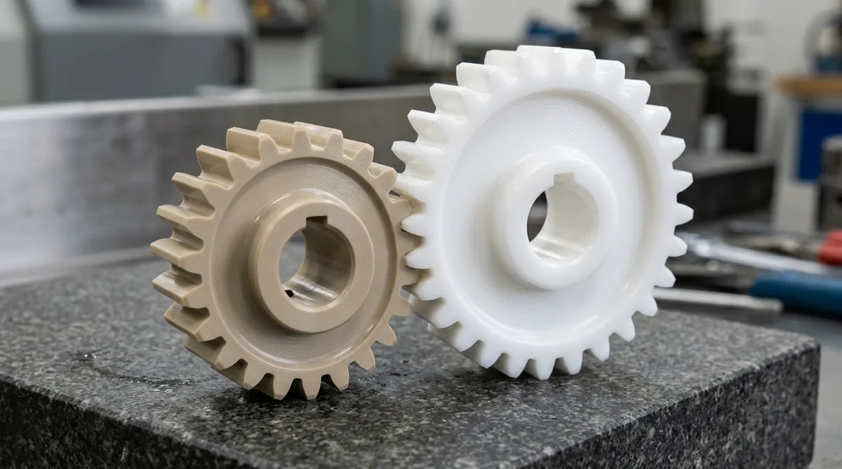
To ensure molded parts meet mechanical and thermal specifications, our process technicians fine-tune injection molding parameters:
- Resin Desiccant Drying: Hygroscopic polymers such as Nylon (PA6/PA66), Polycarbonate (PC), and PBT must be dried in desiccant hopper dryers to dew points below -40°C (residual moisture < 0.02%) to prevent hydrolytic degradation and splay marks.
- Conformal & Baffled Water Cooling: In rapid aluminum molds, drilled cooling water circuits with baffle plugs maintain uniform core and cavity temperatures, minimizing internal molding stresses.
- Decoupled Molding & Scientific Process Control: Utilizing multi-stage cavity pressure transducers to decouple injection fill (95% volumetric fill at velocity control) from packing and holding pressure, ensuring part weight consistency within ±0.2%.
Why Do Low-Volume Plastic Injection Molding Projects Experience Dimensional Warpage or Flash, and How Do You Prevent It?
Managing Low-Volume Plastic Injection Molding successfully requires balancing volumetric shrinkage, cavity clamping pressure, and thermal dissipation across uneven wall cross-sections. While uniform walls of 1.5 to 3.0 mm (0.060″ to 0.118″) stabilize flow fronts within ±0.05 mm (±0.002″), abrupt rib-to-wall transitions exceeding a 0.6:1 ratio induce localized sink marks, internal voids, and residual warpage.
Shop-Floor Quantitative Derivation: Clamping Force, Shrinkage & Thermal Cooling Balance
In our Shenzhen tooling and molding engineering practice, preventing parting-line flash and dimensional drift in Low-Volume Plastic Injection Molding starts with exact clamping tonnage and linear shrinkage compensation before steel or aluminum blocks are cut. Consider a structural housing with a projected cavity area Aproj = 140 cm² (21.7 in²) molded at an internal cavity pressure Pcav = 45 MPa (6,525 psi):
Fclamp = Aproj × Pcav × Sf = 140 cm² × 0.45 kN/cm² × 1.20 = 75.6 tonnes (83.3 US tons)
Simultaneously, tooling cavity dimensions (Dcavity) must compensate for isotropic or anisotropic material shrinkage (S). For a nominal 120.00 mm (4.7244″) datum spacing with a semi-crystalline or alloy shrinkage factor of S = 1.6% (0.016 mm/mm), the machined cavity steel dimension is calculated as Dcavity = Dnom × (1 + S) = 120.00 × 1.016 = 121.92 mm (4.8000″). To lock critical bearing bores or sealing faces within ±0.010 mm (±0.0004″), we leave a 0.40 mm (0.016″) stock allowance for post-molding 3-axis and 4-axis CNC finish milling.
Step-by-Step Shop-Floor Execution & Quality Protocol
To bridge CAD intent with repeatable shop-floor delivery, our engineering team enforces a four-stage execution workflow across every prototype and low-volume production batch:
- Step 1: Rheological Flow & Wall-Thickness DFM Audit: Analyze 3D CAD geometry (STEP/IGES) to verify uniform wall sections, apply 1.0° to 2.5° draft angles per VDI 3400 / SPI texture depth, and position gates away from cosmetic or high-stress zones.
- Step 2: Precision Cavity Machining & Venting Calibration: Machine P20, H13, S136, or 7075-T651 tooling inserts via high-speed CNC milling and Wire/Sinker EDM, grinding perimeter gas vents to 0.015–0.030 mm (0.0006″–0.0012″) depth to evacuate trapped air without flash.
- Step 3: Thermal Stabilization & Scientific Process Windowing: Stabilize mold tool temperature via turbulent conformal/baffle cooling channels (Reynolds number Re > 4,000) and decouple fill, pack, and hold stages to eliminate weld lines and internal porosity.
- Step 4: T1 First-Article Zeiss CMM & Section Verification: Inspect T1 shots after 24-hour thermal conditioning at 20°C (68°F) using Zeiss CMM probing and optical comparator overlays against ISO 2768-mK and drawing GD&T callouts.
Shop-Floor Defect Troubleshooting & Corrective Action Matrix
When evaluating part geometry during pre-production DFM review, our manufacturing engineers screen for the following failure modes and apply proven corrective controls:
| Defect / Symptom | Physical Root Cause | Shop-Floor Corrective Action | Recommended DFM Spec Limit |
|---|---|---|---|
| Parting-Line Flash / Burrs | Insufficient clamp tonnage, excessive injection velocity, or vent depth exceeding 0.04 mm (0.0016″) | Increase clamp safety factor to 1.25×, switch from velocity-to-pressure transfer at 98% fill, and lap parting faces to ≤0.010 mm (≤0.0004″) shutoff. | Flash ≤ 0.05 mm (0.002″) |
| Localized Sink Marks & Voids | Rib-to-wall thickness ratio exceeding 60% causing core thermal contraction after skin freeze | Coring out thick bosses, reducing rib root thickness to 50%–60% of nominal wall, and extending packing pressure until gate freeze-off. | Rib root = 0.5–0.6 × twall |
| Flow Weld / Knit Line Weakness | Converging melt/flow fronts cooling below fusion threshold around cored holes or inserts | Raise melt and mold surface temperatures by 15°C–25°C (27°F–45°F), add overflow wells at knit zones, and relocate gate entry vectors. | Tensile retention ≥ 85% |
| Post-Ejection Warpage & Twist | Differential cooling across asymmetric cavity halves or fiber orientation anisotropy | Balance core/cavity coolant delta within ΔT ≤ 5°C (9°F), anneal stressed parts in precision cooling jigs, and post-machine critical datums. | Flatness ≤ 0.10 mm / 100 mm |
Engineering Trade-Offs: When NOT to Over-Specify
When to Avoid This Process (Engineering Limitations): Do not specify dedicated hard tooling or molding workflows when unit quantities are under 10 pieces and the design geometry is still undergoing weekly functional revisions. In early-stage validation where upfront tooling amortization and 18 to 35 business days of tool fabrication delay testing, direct high-speed 3-axis and 4-axis CNC machining from solid engineering billet or polyurethane vacuum casting (4 to 12 business days ex-factory) delivers superior agility with zero steel modification risk.
🔗 Related Tooling & Molding Engineering Benchmarks:
Optimizing Low-Volume Plastic Injection Molding requires coordinating cavity thermal management, surface texture draft angles, and bridge production pathways. Explore our in-depth guides on Conformal Cooling vs. Conventional Cooling Channels to cut cycle times by 20%–35%, Preventing Flow Marks & Cosmetic Molding Defects, and Polyurethane Vacuum Casting for 10–50 Unit Bridge Runs.
Frequently Asked Questions
Aluminum molds (using alloys like 7075-T651) machine up to 3 times faster than steel, reducing upfront tooling costs by 40% to 60% and optimizing lead times to 18-35 business days. Furthermore, aluminum’s superior thermal conductivity cuts injection cooling cycles nearly in half, reducing per-part molding costs.
Yes. High-strength aluminum molds easily process standard thermoplastics including ABS, PC, POM, and PP. When molding abrasive glass-filled resins (e.g., PA66-GF30), aluminum tools can reliably produce 1,000 to 3,000 parts, or the mold cavities can be hard-anodized or localized in P20 steel inserts for extended life.
Automatic mechanical side-actions require intricate slides, angle pins, and locking blocks that drive up mold manufacturing costs. Hand-loaded inserts are placed into the mold by hand before each shot and ejected with the part, allowing undercuts and threads to be molded with minimal tooling complexity for batches of 100 to 2,000 parts.
Planning the Pilot Run: T1 Samples, Process Window and Steel-Safe Corrections
A low-volume molding pilot run should confirm gate location, fill balance and shrinkage on T1 samples before dimension-critical features are corrected in steel, because aluminum and pre-hardened tools can be adjusted far faster than hardened production dies.
- T1 evaluation: Run a short-shot study to map the fill pattern, then measure the critical dimensions after the parts stabilize to establish the actual shrinkage for the selected resin.
- Process window: Vary melt temperature, injection speed and packing pressure in a small experiment to find the range that produces acceptable parts, rather than relying on a single optimized setting.
- Venting and wear checks: Inspect vents and shut-off surfaces after the first run, since flash or burn marks at the end of fill signal vents that need to be deepened or cleaned.
- Steel-safe corrections: Design cores and cavities with extra metal on critical features, so dimensional corrections remove metal from the tool instead of requiring weld repair.
Treating the first pilot run as a structured experiment shortens the correction cycle and gives the customer defensible data on shrinkage, warpage and gate vestige before volume production decisions are made.
Scale Production with Low-Volume Plastic Injection Molding
Bridge the gap from prototype to production with fast, cost-effective rapid tooling. Our experienced moldmakers and injection process engineers ensure your parts achieve production-grade mechanical performance with minimal upfront capital.
Upload your 3D CAD files (STEP, IGES, or Parasolid) today for an in-depth DFM moldability analysis and quotation: