In high-precision manufacturing, waiting until final quality control to inspect a machined component is an obsolete and financially perilous strategy. Final inspection merely acts as a sorting gate—identifying defective parts only after 100% of the raw material, machine hours, cutting tools, and labor have already been consumed.
To achieve zero-defect serial production with micron-level repeatability, advanced machine shops deploy In-Process Inspection (In-Process Quality Control / IPQC). In precision manufacturing, mastering in process inspection in cnc machining ensures repeatable dimensional stability and predictable production scaling.
At AS Prototypes, quality is not tested into a part after the fact; it is systematically engineered into every step of the machining process. In this comprehensive technical guide, our quality assurance directors and CNC manufacturing engineers explore the methodologies, on-machine probing technologies, statistical process controls (SPC), and operational gates that define world-class in-process metrology.
Executive Summary & Engineering Takeaways (BLUF)
- Core Focus & DFM Scope: Actionable shop-floor engineering guidelines for in process inspection in cnc machining, covering material selection, geometric tolerancing, and defect prevention.
- Achievable Tolerance Envelope: General features hold ISO 2768-mK; critical bearing bores, dowel pins, and mating datums hold ±0.010 to ±0.020 mm (±0.0004″ to ±0.0008″), with Wire EDM/grinding to ±0.005 mm (±0.0002″).
- Machining & Surface Integrity: High-speed 3-axis and 4-axis VMCs (with simultaneous 5-axis for complex contours) delivering as-machined Ra 0.8 µm (32 µin) to Ra 0.4 µm (16 µin) per ASME B46.1.
- Metrology & Process Control: On-machine spindle probing paired with 20°C ± 1°C (68°F) climate-controlled Zeiss Bridge CMM coordinate verification (available upon request for critical dimensional inspection) and calibrated Go/No-Go plug/ring gauges.
- Ex-Factory Turnaround: 4 to 8 business days for as-machined rapid prototypes; 7 to 12 business days for anodized, plated, or multi-operation production runs (excluding 3–5 days air transit).
Article Engineering Navigation
- 1. The Economics of Quality: The 1-10-100 Rule
- 2. On-Machine Measurement (OMM) and Closed-Loop Metrology
- 3. The 4 Operational Milestones of In-Process Inspection
- 4. Shop-Floor Metrology Tooling Spectrum
- 5. Engineering Case Study: Eliminating Thermal Drift Scrap in 316L Hydraulic Spool Machining
- 6. Best Practices for Implementing Flawless In-Process Inspection
- 7. Why Choose AS Prototypes for Zero-Defect Precision Machining?
- 8. Technical Engineering FAQ
1. The Economics of Quality: The 1-10-100 Rule
The primary driver behind rigorous in-process inspection is the classic manufacturing Rule of Tens (1-10-100 Rule):
- Prevention / In-Process (1x Baseline): Catching a cutting tool wear drift or fixture misloading during operation OP10 incurs only a 1x baseline cost in simple tool offset adjustment or scrap of a single rough billet.
- Final Inspection (10x Escalation): Discovering the defect during final CMM layout after OP20 milling, heat treatment, and surface anodizing escalates loss by 10x—scrapping a fully finished, high-value component and wasting allocated spindle capacity.
- Customer Escapes (100x+ Escalation): If a defective component slips past final inspection and fails during the customer’s subsystem assembly or aerospace flight testing, containment costs, warranty claims, line stoppages, and reputational damage exceed 100x the in-process prevention effort.
By embedding verified metrological checkpoints throughout the manufacturing workflow, IPQC converts quality control from a reactive post-mortem into a proactive, closed-loop defect prevention system.
2. On-Machine Measurement (OMM) and Closed-Loop Metrology
The cutting edge of in-process inspection involves measuring the workpiece while it remains clamped inside the CNC machine tool envelope. Removing a workpiece from a fixture to measure it on an external coordinate measuring machine (CMM) destroys setup alignment and introduces re-chucking errors (±0.005 mm to 0.020 mm). On-Machine Measurement (OMM) eliminates this limitation.
1. High-Precision Spindle Touch Probes
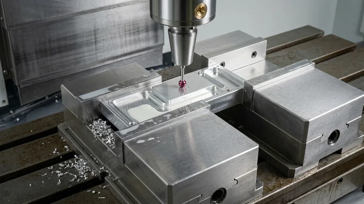
Modern 3-axis, 4-axis, and 5-axis machining centers are equipped with optical or radio-frequency wireless touch-trigger inspection probes (such as Renishaw OMP60 or Blum-Novotest TC50). Using micro-ruby styli, these probes execute automated macro routines directly inside the G-code program:
- Pre-Machining Stock & Datum Alignment: The probe measures the raw billet’s true position, rotation, and stock allowance, dynamically updating the Work Coordinate System (WCS: G54–G59) to eliminate manual edge-finding errors.
- In-Cycle Semi-Finishing Verification: Following roughing and semi-finishing, the probe measures critical bore diameters and wall distances. If tool deflection or thermal drift is detected, the CNC macro program automatically recalculates the tool wear offset (Δ D, Δ L) and immediately triggers a compensating spring cut.
- Feature Verification Before De-Clamping: Thread depths, deep pocket depths, and boss centerlines are verified before releasing the fixture jaws, ensuring that any necessary secondary cuts occur under the original datum reference frame.
2. Non-Contact Laser Tool Setters
Tool degradation is a continuous variable. Utilizing non-contact laser tool setters (such as Renishaw NC4), cutting tools are measured dynamically at operating spindle speeds (e.g., 12,000 RPM). The laser detects tool length, effective cutting diameter, dynamic runout, and microscopic chipping on cutting edges with micron-level repeatability. If tool wear exceeds predetermined limits, the CNC automatically calls a redundant sister tool from the magazine before surface gouging occurs.
3. The 4 Operational Milestones of In-Process Inspection
A comprehensive IPQC protocol establishes clear, non-negotiable verification gates throughout a production run:
Milestone 1: First Article Inspection (FAI)
Prior to authorizing serial production on any CNC setup, the first 1 to 3 components off the machine must undergo a rigorous First Article Inspection (FAI) verifying critical drawing characteristics. The FAI report cross-references ballooned drawing dimensions, geometric tolerances (GD&T datums, true position, runout, parallelism), material mill test documentation, and surface roughness parameters (Ra per ISO 4287). Production remains locked until the quality department formally signs off on the FAI setup approval.
Milestone 2: Inter-Operational Gates (Before Irreversible Processes)
Certain manufacturing processes permanently alter the physical state of a component. In-process inspection must be placed strategically immediately prior to:
- Heat Treatment & Stress Relief: Verifying rough pocket depths and critical wall stock allowances (0.8–1.2 mm) to ensure sufficient material remains for post-heat-treat finishing.
- Surface Finishing / Plating / Anodizing: Checking pre-plate thread pitch diameters (using special oversize thread plug gauges) and internal bore dimensions. Anodizing (MIL-A-8625 Type II or Type III Hardcoat) penetrates ~50% into the substrate and builds up ~50% outward (adding ~5–12 µm per surface for Type II and ~15–25 µm per surface for Type III Hardcoat, reducing internal bore diameters by 0.010 to 0.050 mm total); catching an undersized bore before anodizing avoids costly chemical stripping and part rework.
- Secondary Multi-Axis Setup Flipping (OP10 to OP20): Inspecting internal ports, cross-holes, and O-ring seal grooves that become physically inaccessible once the component is re-clamped for reverse-side facing.
Milestone 3: Patrol / Roving Periodic Inspection & SPC
During serial manufacturing, traveling quality inspectors conduct periodic roving inspections at defined intervals (e.g., every 60 minutes or every 10 parts):
- Statistical Process Control (SPC): Inspectors record critical dimensions using Bluetooth-connected digital metrology instruments that beam measurements directly into SPC software.
- X-bar and R Control Charts: By monitoring sample averages (X̄) and ranges (R), quality engineers identify unnatural process trends (such as gradual tool wear drift toward upper specification limits) long before parts exceed customer tolerance boundaries.
Milestone 4: Tool Change and Reset Verification
Whenever a machine operator indexes a carbide insert, swaps an end mill, or unclamps a fixture for cleaning, a mini-revalidation is mandatory. The very next part produced must be measured for the specific features governed by that tool before the machine is returned to unattended cycle mode.
4. Shop-Floor Metrology Tooling Spectrum
Deploying the correct measurement instrument at the machine side is critical to balancing inspection speed against measurement uncertainty:
| Inspection Tooling | Measurement Type | Resolution / Accuracy | Inspection Cycle Time | Primary Quality Purpose |
|---|---|---|---|---|
| On-Machine Touch Probe | In-situ 3D point probing | 2σ repeatability (≤0.005 mm) | 15–45 seconds | WCS datum alignment, automated tool wear compensation |
| Digital Micrometer / Bore Gauge | OD / ID 2-point contact | ±0.005 mm accuracy | 10–20 seconds | Shaft diameters, bore sizes, web wall thicknesses |
| Mitutoyo 3-Point Internal Micrometer (Holtest) | Self-centering 3-point carbide contact | 0.001 mm resolution (±0.002 mm accuracy) | 2–5 seconds | Critical hydraulic valve bores, roundness, taper |
| Hardened Go / No-Go Gauges | Attribute limit check | Class X / XX tolerance | 3–5 seconds | Thread pitch diameter, pin bore minimum/maximum clearance |
| Optical Vision Measuring System | Telecentric optical camera | ±0.005 mm | 3 seconds (up to 99 features) | Complex 2D profiles, stamped parts, multi-hole patterns |
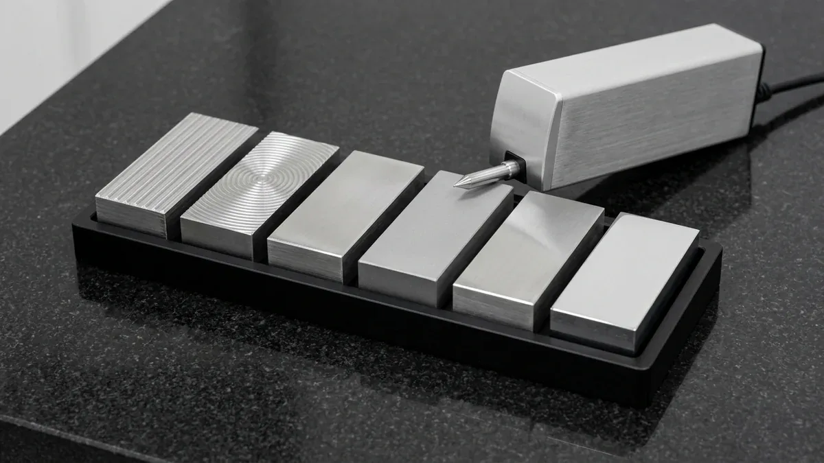
| Portable Surface Profilometer | Diamond stylus skid tracing | 0.01 μm Ra | 15–30 seconds | Milled/turned sealing surfaces, O-ring groove finishes |
5. Engineering Case Study: Eliminating Thermal Drift Scrap in 316L Hydraulic Spool Machining
The Problem
An industrial fluid power manufacturer contracted AS Prototypes to produce 1,200 serialized hydraulic valve sleeves in medical-grade AISI 316L stainless steel. The internal valve bore specified an ISO H7 diameter of 10.000 mm (+0.015 / -0.000 mm) with a maximum cylindricity tolerance of 0.008 mm and surface finish Ra ≤ 0.4 μm.
In traditional shift production, thermal heat accumulation in the CNC lathe spindle combined with work-hardening of 316L caused gradual bore shrinkage during afternoon runs. Because inspection was originally conducted at the end of the shift in the central CMM room, 14.5% of parts were rejected as undersized scrap, resulting in severe delivery bottlenecks.
AS Prototypes IPQC Intervention
- Dedicated Machine-Side 3-Point Bore Gauging: Deployed calibrated Mitutoyo three-point internal micrometers (Holtest) and Class X Go/No-Go cylindrical plug gauges directly adjacent to the CNC lathe table. Operators checked critical bores within 10 seconds of part ejection.
- Digital SPC Closed-Loop Feedback: Bore micrometer readings were automatically logged into a real-time SPC tablet. When the bore diameter drifted within 0.004 mm of the lower specification limit, an automated alert signaled the machine operator to compensate the finishing boring bar wear offset.
- Laser Tool Setting Integration: Integrated non-contact laser tool measurement to verify the boring bar micro-insert tip condition every 35 cycles, catching micro-chipping before it damaged bore surface roughness.
- Thermal Equalization Standard: Introduced a brief 3-minute isothermal bath soak for sample parts prior to secondary reaming verification to eliminate thermal measurement error.
The Results
- Scrap Rate Reduction: Bore rejection plummeted from 14.5% to 0.12% across the entire production run.
- Process Capability (Cpk): Achieved a sustainable Cpk of 1.84 (exceeding automotive Tier 1 requirements).
- Delivery Timeline: Completed production 11 days ahead of schedule, with 100% full digital traceability dossiers provided to the client.
6. Best Practices for Implementing Flawless In-Process Inspection
To establish a robust IPQC culture on the factory floor, manufacturing managers must follow these foundational operational principles:
- Thermal Stabilization Awareness: Aluminum expands at roughly 23 μm/m · °C, and steel at 12 μm/m · °C. Machined parts straight out of heavy cutting fluid can be 15°C warmer than standard 20°C reference environments. High-precision inspection stations must use temperature-compensated gauges or brief isothermal balancing baths before recording final data.
- Rigorous Calibration & Gage R&R: Measurement instruments are only as reliable as their calibration records. All hand tools, plug gauges, and touch probes must maintain up-to-date NIST-traceable calibration reports, with annual Gage R&R repeatability studies holding system variation below 10% (%GRR < 10%).
- Poka-Yoke Physical Fixturing: In-process checks should not rely exclusively on human alertness. Design checking fixtures with asymmetrical locating pins and mechanical interlocks (Poka-Yoke) so parts cannot physically seat if a prior operation (such as a drilled hole or milled notch) was omitted.
- Empower Machinists to Stop the Line: A true Lean manufacturing culture gives machine operators the absolute authority and responsibility to halt a spindle immediately upon noticing an out-of-trend SPC point, preventing the generation of continuous defect batches.
7. Why Choose AS Prototypes for Zero-Defect Precision Machining?
High-precision machining is not just about having powerful spindles—it is about having the metrological discipline to ensure that every single feature leaving the machine conforms exactly to your CAD model and GD&T specifications.
At AS Prototypes, our Shenzhen manufacturing facility operates over 30 advanced 3-, 4-, and 5-axis CNC machining centers integrated with wireless Renishaw in-situ probing, laser tool presetting, Mitutoyo three-point internal micrometers (Holtest), calibrated Go/No-Go gauges, and a 20°C ± 1°C climate-controlled metrology laboratory equipped with a Zeiss Bridge CMM (available upon request), 2.5D optical vision measuring systems (VMS), and contact stylus profilometers (ISO 4287).
Shop-Floor Cost-Tolerance Trade-Offs & When NOT to Over-Specify
When releasing production drawings for in process inspection, applying blanket ±0.010 to ±0.020 mm (±0.0004″ to ±0.0008″) tolerances across non-mating clearance features increases machining cycle time by 2.0× to 3.5× without improving functional assembly. Our DFM engineers recommend specifying ISO 2768-mK on general structural walls while isolating tight GD&T callouts strictly to functional bearing bores, dowel pins, and sealing interfaces.
In our Shenzhen facility, prismatic 3-axis and 4-axis vertical machining centers (VMCs) with contoured soft jaws handle 80%+ of structural setups with maximum rigidity and cost efficiency, reserving simultaneous 5-axis contouring strictly for compound-angle ports and organic impellers. Critical features undergo climate-controlled 20°C ± 1°C (68°F) Zeiss Bridge CMM verification (available upon request) prior to ex-factory release (4 to 8 business days for raw prototypes; 7 to 12 business days with MIL-A-8625 anodizing or ASTM A967 passivation).
🔗 Related CNC DFM & Metrology Engineering Guides:
To further optimize cycle time and dimensional stability in in-process probed CNC components, combine proper internal corner relief with datum-based coordinate inspection. Consult our shop-floor engineering guides on Maintaining Dimensional Stability in Thin-Wall Machining, Eliminating Sharp Internal Corners & Tool Deflection, and Precision CMM Metrology & GD&T Verification.
8. Technical Engineering FAQ
Final First Article Inspection (FAI) is a post-manufacturing gate performed in the metrology lab after all machining setups are finished, which means any out-of-tolerance feature discovered at that stage results in scrapped parts. In-process inspection verifies critical datums, roughing allowances, and tight bores directly on the CNC machine table or between intermediate setups—catching thermal drift and tool wear while corrective compensation cuts can still be executed.
A kinematic optical or radio-transmission spindle probe (such as a Renishaw OMP60/RMP60) touches off on a semi-finished bore or datum boss while the workpiece remains clamped. The CNC macro compares the measured coordinate against the nominal CAD value and automatically updates the G54–G59 work offset or dynamic tool wear register (G41/G42) by the exact micron deviation prior to running the final finishing pass.
Process capability index Cp measures the ratio of the drawing tolerance width (USL − LSL) to the natural 6σ process spread, whereas Cpk accounts for how well the process mean (µ) is centered within the tolerance band. In batch precision machining, maintaining Cpk ≥ 1.33 (and Cpk ≥ 1.67 on critical bearing or sealing interfaces) triggers automated tool-wear offset adjustments before dimensions ever approach the drawing limits.
On-machine verification is essential before unclamping heavy 5-axis aerospace manifolds, large thin-wall aluminum enclosures, or tight-tolerance bearing housings (±0.010 mm). Once a part is unclamped from its custom soft jaws or vacuum fixture, re-establishing the exact primary/secondary datum alignment within ±0.005 to ±0.010 mm is time-consuming; verifying dimensions while clamped guarantees single-setup geometric integrity.
Partner with Our Precision CNC Machining & Engineering Team
Eliminate tool deflection, residual stress distortion, and tolerance stack-up risks before production begins. Upload your 3D CAD files (STEP/IGES) and 2D GD&T drawings for a comprehensive shop-floor DFM review and custom quotation.
Upload 3D CAD for Engineering DFM & RFQ