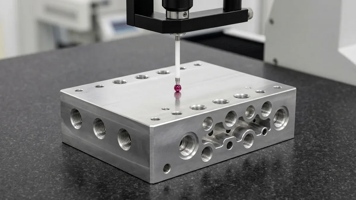
In high-precision manufacturing, traditional quality control has historically functioned as a post-mortem autopsy: an expensive, multi-axis workpiece is machined, unbolted from its precision fixtures, washed, de-burred, and transported to an offline climate-controlled metrology laboratory for Coordinate Measuring Machine (CMM) inspection.
If a single critical bore is undersized by 15 microns or an optical datum has drifted due to cutter deflection, the engineering team faces a brutal dilemma: scrap the expensive workpiece entirely, or attempt the nearly impossible feat of re-clamping and re-indicating the part with tight-tolerance datum alignment.
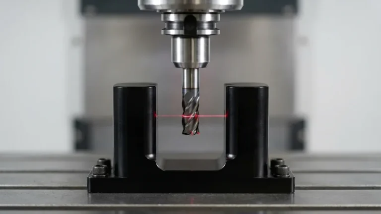
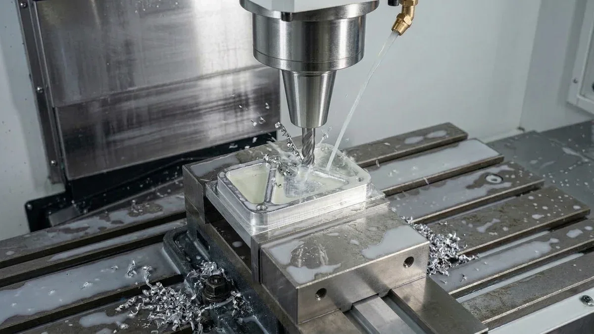
On-Machine Inspection (OMI)—often referred to as On-Machine Verification (OMV) or In-Process Probing—radically transforms this legacy paradigm. By mounting high-accuracy wireless touch-trigger probes, optical scanning heads, and non-contact laser tool setters directly within the CNC machine tool envelope, OMI turns the machining center into an active, self-correcting metrology station.
Parts are inspected while still locked in their original Work Coordinate System (WCS). If deviations are detected, closed-loop macros automatically update tool wear registers, compensate for thermal growth, and trigger immediate adaptive finishing passes—eliminating scrap before the vise jaws are ever opened.
Executive Summary & Engineering Takeaways (BLUF)
- Core Focus & DFM Scope: Actionable shop-floor engineering guidelines for on-machine inspection, covering material selection, geometric tolerancing, and defect prevention.
- Achievable Tolerance Envelope: General features hold ISO 2768-mK; critical bearing bores, dowel pins, and mating datums hold ±0.010 to ±0.020 mm (±0.0004″ to ±0.0008″), with Wire EDM/grinding to ±0.005 mm (±0.0002″).
- Machining & Surface Integrity: High-speed 3-axis and 4-axis VMCs (with simultaneous 5-axis for complex contours) delivering as-machined Ra 0.8 µm (32 µin) to Ra 0.4 µm (16 µin) per ASME B46.1.
- Metrology & Process Control: On-machine spindle probing paired with 20°C ± 1°C (68°F) climate-controlled Zeiss CMM coordinate verification (available upon request) and calibrated Go/No-Go plug/ring gauges.
- Ex-Factory Turnaround: 4 to 8 business days for as-machined rapid prototypes; 7 to 12 business days for anodized, plated, or multi-operation production runs (excluding 3–5 days air transit).
Article Engineering Navigation
- 1. What is On-Machine Inspection? Principles & Closed-Loop Architecture
- 2. Key Probing Technologies: Contact Touch Probes vs. Non-Contact Vision & Lasers
- 3. The Critical Engineering Reality: OMI vs. Standalone CMM Metrology
- 4. On-Machine Inspection vs. Standalone CMM Metrology Matrix
- 5. Real-World Case Studies: Closed-Loop Probing in Action at AS Prototypes
- 6. Conclusion: The Smart Manufacturing Advantage at AS Prototypes
- 7. Technical Engineering FAQ
1. What is On-Machine Inspection? Principles & Closed-Loop Architecture
On-Machine Inspection refers to automated metrology routines executed directly within the machine tool’s operational envelope during the manufacturing cycle. Rather than serving purely as a final pass/fail gate, OMI operates as an active process control loop consisting of four sequential phases:
- Automated Workpiece Setup & WCS Alignment: Spindle probes automatically touch cast or saw-cut billet edges, cast bosses, or zero-point chucks, establishing precise X, Y, Z origins and rotational skew angles (G54–G59, G68) in under 60 seconds, completely replacing manual edge finders and dial test indicators.
- In-Process Dimensional Verification: Following roughing or semi-finishing operations, the spindle probe automatically interrogates critical features—such as deep bores, thin-wall web thicknesses, and contoured surface datums—before final finishing.
- Dynamic Closed-Loop Feedback: Measurement data is compared directly to nominal CAD coordinates within the CNC controller. Macro routines automatically calculate tool wear offsets, updating the controller’s tool compensation table (D and H registers) to offset cutter deflection and abrasive tool wear.
- Adaptive Clean-Up Machining: If an undersized condition is identified, the controller triggers an automatic clean-up toolpath to remove the remaining stock without manual operator intervention.
2. Key Probing Technologies: Contact Touch Probes vs. Non-Contact Vision & Lasers
Modern advanced CNC machine shops deploy a synergistic combination of contact and non-contact inspection sensors tailored to specific feature geometries:
1. Kinematic & Strain-Gauge Touch-Trigger Probes
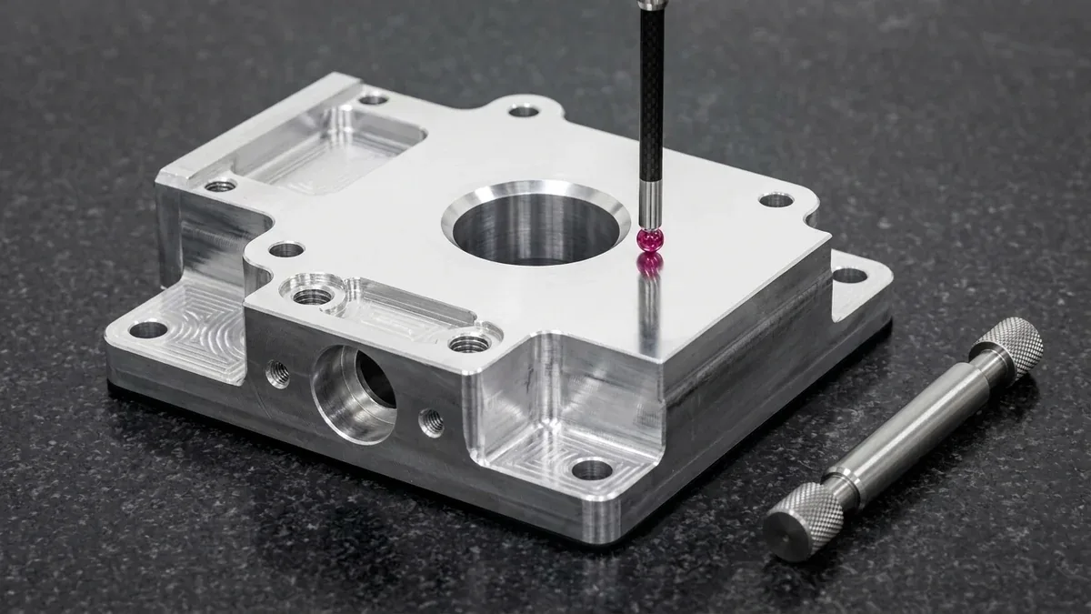
Mounted in standard toolholders (CAT40, HSK-63A, or CAPTO), touch probes communicate with machine optical or radio receivers (e.g., Renishaw RMP60 / OMP40, Heidenhain TS series, Blum-Novotest). When the ruby ball stylus touches the workpiece, internal kinematic electrical contacts or piezo-resistive strain gauges trigger a microsecond skip signal (G31) to the CNC controller, latching instantaneous axis scale positions with repeatability down to ≤ 0.25 μm. Strain-gauge probes offer exceptional 3D lobing resistance, making them ideal for complex aerospace 5-axis contoured surfaces.
2. Non-Contact Laser Tool Setters
Stationary laser transmitter-receiver units mounted on the machine table emit a focused laser beam. As cutting tools rotate at operating speeds (10,000–24,000 RPM), the cutter interrupts the beam, allowing the system to measure dynamic tool length, effective cutting diameter under centrifugal force, and individual flute chipped-edge runout in real time. This ensures broken drills or worn end mills are flagged before they ruin expensive workpieces.
3. High-Resolution Machine Vision & CCD Cameras
For hybrid multi-material parts—such as metal-plastic overmolded assemblies or delicate silicon substrates where physical probe contact might scratch optical surfaces—spindle-mounted or enclosure-fixed CCD industrial cameras capture high-contrast boundary contours. Edge-detection algorithms calculate centroid coordinates and angular orientations, transmitting adaptive machining offsets directly to the CNC program.
3. The Critical Engineering Reality: OMI vs. Standalone CMM Metrology
A common misconception in manufacturing engineering is that On-Machine Inspection makes offline Coordinate Measuring Machines obsolete. In rigorous aerospace and medical manufacturing, this assumption is dangerously flawed:
The “Self-Audit” Limitation of Machine Tools: When a CNC machine inspects a part using its own axes, the measurement relies on the machine’s own linear scales, ball screws, guideways, and rotary bearings. If the machine’s Y-axis has a 12-micron leadscrew pitch error, or the spindle carrier has tilted due to thermal expansion (20°C to 35°C during heavy cutting), the touch probe will travel along that distorted kinematic path—effectively measuring the part as “perfect” even when a geometric error exists.
Therefore, AS Prototypes deploys OMI and CMM as complementary pillars of a zero-defect manufacturing ecosystem:
- OMI’s Primary Mission: In-process error prevention, scrap elimination, setup automation, and adaptive tool wear compensation while the part can still be corrected.
- CMM’s Primary Mission: Independent quality assurance executed on an isolated granite structure within a calibrated climate-controlled metrology laboratory (20°C ± 1°C), providing fully traceable comprehensive FAI inspection reports (available upon request) free of machine kinematic bias.
4. On-Machine Inspection vs. Standalone CMM Metrology Matrix
The comparative matrix below illustrates the distinct roles, technical strengths, and measurement uncertainties of OMI compared to offline CMM metrology:
| Metrology Parameter | On-Machine Inspection (OMI / In-Process) | Standalone CMM Metrology (Offline QC) |
|---|---|---|
| Timing & Location | During machining; inside CNC machine cutting envelope | Post-machining; dedicated climate-controlled metrology lab |
| Coordinate Reference | Machine linear glass scales & rotary encoders (WCS G54) | Ultra-precise Zerodur scales on air-bearing granite guideways |
| Thermal Environment | Variable (20°C–35°C), affected by cutting heat & coolant | Strictly stabilized (20°C ± 1°C, 45% RH) |
| Rework Capability | Immediate: Part is still clamped; can re-machine instantly | Difficult: Part uncoupled; re-alignment introduces datum errors |
| Measurement Uncertainty | ± 3 μm to ± 8 μm (Constrained by machine geometry) | ± 1.5 μm + L/350 (Zeiss Bridge CMM, available upon request) |
| Process Setup Time | 1 to 2 minutes: Fully automated probing macro | 15 to 45 minutes: Fixturing, stylus calibration, alignment |
| Primary Quality Function | In-process prevention, tool wear compensation & zero-defect gating | Final traceability, GD&T documentation & customer compliance FAI |
5. Real-World Case Studies: Closed-Loop Probing in Action at AS Prototypes
To demonstrate the transformative impact of integrated in-process probing, consider two high-demand manufacturing projects executed at AS Prototypes:
Case Study 1: Zero-Scrap Aerospace 7075 Structural Bulkhead (300 Units)
- Part Requirements: 5-axis machined AL7075-T651 aerospace structural housing with 126 drawing dimensions, including 22 critical H7 pin bores (Ø 12.000 mm +0.018/-0.000 mm) and tightly toleranced pocket wall webs (1.20 mm ± 0.025 mm). Zero-defect customer acceptance policy.
- The Traditional Bottleneck: Offline CMM inspection of first-article prototypes revealed unpredictable tool wear drift after 15 parts, resulting in undersized bores and scrap rates exceeding 6%.
- AS Prototypes OMI Closed-Loop Solution: We integrated a Renishaw RMP60 strain-gauge touch probe into the 5-axis machining cycle. Before final reaming and bore finishing, the probe measured each bore in four quadrature points. If the diameter approached the lower control limit (< +0.005 mm), the CNC macro dynamically updated tool radial offsets by +0.006 mm and executed an immediate re-machining spring pass before unclamp.
- Results: 100% first-pass yield across all 300 production units. Rework was completely eliminated, and cycle time was reduced by 35% compared to offline round-trip inspection.
Case Study 2: High-Precision Optical Alignment on Hybrid Aluminum-Plastic Audio Manifold
- Part Requirements: Precision consumer audio housing featuring CNC-machined 6061-T6 aluminum overmolded with black polycarbonate-ABS. The critical Ø 3.50 mm audio jack aperture required concentric wall thickness uniformity within ±0.020 mm relative to the molded polymer boundary.
- The Fixturing Challenge: Because the overmolding process exhibited slight volumetric shrinkage variations from shot to shot, standard mechanical locating pins could not establish a reliable datum. Contact mechanical touch probes risk scratching the molded cosmetic face.
- AS Prototypes Machine Vision Solution: We fitted the CNC spindle with a high-resolution telecentric CCD vision inspection camera. Using pressurized cold vortex air, cutting debris was evacuated from the lens field. The optical vision system captured the visual contrast boundary between the aluminum bezel and the molded plastic, mathematically fitting a best-fit circle center. The calculated X, Y coordinate offsets were transmitted directly to the Fanuc CNC controller via Ethernet in 1.2 seconds.
- Results: Every aperture was machined precisely concentric to its individual molded boundary, holding wall thickness variation within ±0.008 mm and completely eliminating visual misalignment rejections.
6. Conclusion: The Smart Manufacturing Advantage at AS Prototypes
On-Machine Inspection is the cornerstone of modern Industry 4.0 subtractive manufacturing. By bridging the gap between cutting kinematics and dimensional metrology, OMI empowers precision machine shops to identify defects while parts can still be corrected, automate datum setups, and maintain exceptional Statistical Process Control (Cpk ≥ 1.67).
At AS Prototypes, our 3-axis, 4-axis, and 5-axis machining centers are equipped with calibrated Renishaw and Blum probing systems, synchronized seamlessly with our 20°C ± 1°C climate-controlled metrology laboratory. Whether you require rapid prototyping of mission-critical aerospace brackets or scalable production of microfluidic manifolds, our closed-loop quality architecture guarantees uncompromised precision from first article to final delivery.
Shop-Floor Cost-Tolerance Trade-Offs & When NOT to Over-Specify
When releasing production drawings for on machine inspection for CNC machining, applying blanket ±0.010 to ±0.020 mm (±0.0004″ to ±0.0008″) tolerances across non-mating clearance features increases machining cycle time by 2.0× to 3.5× without improving functional assembly. Our DFM engineers recommend specifying ISO 2768-mK on general structural walls while isolating tight GD&T callouts strictly to functional bearing bores, dowel pins, and sealing interfaces.
In our Shenzhen facility, prismatic 3-axis and 4-axis vertical machining centers (VMCs) with contoured soft jaws handle 80%+ of structural setups with maximum rigidity and cost efficiency, reserving simultaneous 5-axis contouring strictly for compound-angle ports and organic impellers. Critical features undergo climate-controlled 20°C ± 1°C (68°F) Zeiss CMM verification (available upon request) and calibrated Go/No-Go gauging prior to ex-factory release (4 to 8 business days for raw prototypes; 7 to 12 business days with MIL-A-8625 anodizing or ASTM A967 passivation).
🔗 Related CNC DFM & Metrology Engineering Guides:
To further optimize cycle time and dimensional stability in on-machine probed CNC components, combine proper internal corner relief with datum-based coordinate inspection. Consult our shop-floor engineering guides on Maintaining Dimensional Stability in Thin-Wall Machining, Eliminating Sharp Internal Corners & Tool Deflection, and Precision CMM Metrology & GD&T Verification.
7. Technical Engineering FAQ
OMI uses spindle touch-probes for in-process datuming, stock verification, and dynamic tool wear compensation. Offline CMM provides independent, climate-controlled final verification isolated from machine errors.
A CNC machine cannot independently audit its own systematic geometric errors. If a machine axis has thermal pitch error, the on-machine probe follows the same deformed path, masking dimensional flaws.
By probing critical bores between semi-finishing and finishing, the machine detects insert wear trends and automatically updates tool wear offsets (G43.1 / G54) before dimensions drift outside specification.
Partner with Our Precision CNC Machining & Engineering Team
Eliminate tool deflection, residual stress distortion, and tolerance stack-up risks before production begins. Upload your 3D CAD files (STEP/IGES) and 2D GD&T drawings for a comprehensive shop-floor DFM review and custom quotation.
Upload 3D CAD for Engineering DFM & RFQ