Master robotics prototyping from CAD to field validation: 3/4/5-axis joint milling, harmonic housing tolerances, lightweight alloys, and CMM metrology.
Kinematic Coaxiality Demands: Strain wave (Harmonic Drive), RV cycloidal, and planetary joint actuators require CNC fine-bored aluminum housing bearing seats held to ISO H7/JS6 (±0.008 to ±0.012 mm / ±0.0003″ to ±0.0005″), ground steel shafts to ISO h5/g6 (±0.005 mm / ±0.0002″), and opposing bore coaxiality ≤ 0.010 mm to prevent gear tooth scuffing and non-linear torque ripple.
Shop-Floor Machine Division: High-speed 3-axis and 4-axis VMCs execute 75%–85% of bulk roughing and prismatic chassis work; simultaneous 5-axis CNC milling is deployed strategically for monolithic joint gimbals and skeletal contours, while Swiss-type CNC lathes turn Ø1.0–Ø6.0 mm dexterous hand pins and linear shafts.
Alloy & Lightweighting Selection: Aerospace 7075-T651 (σy ≈ 503 MPa / 73 ksi) maximizes specific stiffness for joint housings and bipedal limbs; 40CrNiMoA / 4340 and 17-4PH H900 handle high-fatigue splines and linear roller-screw shafts; Ti-6Al-4V Grade 5 reinforces shock-loaded ankle/wrist yokes.
Thermal & Sealing Integrity: Frameless BLDC stators rely on ISO H7/m6 or H7/js6 press-fits bored to Ra ≤ 0.4 μm (16 μin) for heat conduction, paired with MIL-A-8625 Type III hardcoat exterior anodizing and selective MIL-DTL-5541 conductive grounding pads.
Ex-Factory Turnaround: 4 to 8 business days for as-machined rapid prototypes; 7 to 12 business days for anodized, heat-treated, or precision-ground assemblies (strictly separated from 3–5 business days air transit).
Written by: AS Prototypes Precision Engineering Team | Technically Reviewed by: Senior Multi-Axis CNC, Swiss Turning & Robotics Metrology Specialist
Executive Summary & Engineering Takeaways (BLUF)
Kinematic Coaxiality Demands: Strain wave (Harmonic Drive) and cycloidal gearboxes require rigid bearing journal concentricity within ≤ 0.008 mm. Angular tilt greater than 0.015° induces uneven gear tooth scuffing, accelerated wear, and non-linear torque ripple.
Shop-Floor Machine Reality: High-speed 3-axis and 4-axis vertical machining centers (VMCs) handle 75% to 85% of robotics structural machining (chassis, crossbeams, motor brackets, and cooling manifolds). Simultaneous 5-axis CNC milling is deployed strategically for monocoque joint gimbals, organic limb links, and multi-directional cable routing cavities.
Alloy & Composite Selection: Aerospace-grade 7075-T651 aluminum delivers optimal specific yield strength (σy ≈ 503 MPa) for high-torque joint housings, while 6061-T6 provides corrosion resistance and weldability for structural chassis. Ti-6Al-4V Grade 5 is reserved for severe shock-load wrist and knee shafts.
Thermal Dissipation Architecture: High-power frameless BLDC stators rely on precise housing press-fits (ISO H7/m6) and conduction paths (k ≈ 130 W/m·K for 7075-T6) to prevent thermal demagnetization during sustained stall torque.
Sub-Assembly CMM Verification: Full ASME Y14.5-2018 GD&T coordinate inspection on bridge CMMs verifies bearing bore cylindricity, perpendicularity, and datum alignment prior to mechanical integration.
1. Mechatronic Engineering Bottlenecks in Modern Robotics Prototyping
Physical robotics prototyping differs fundamentally from traditional industrial machinery design. Stationary automation equipment can afford massive cast-iron frames and oversized servo drives to guarantee positioning accuracy. By contrast, modern bipedal humanoids, quadruped robots, and multi-axis collaborative robotic arms operate under strict payload-to-weight constraints, high dynamic acceleration envelopes (often exceeding 2g to 5g in dynamic gait cycles), and severe dimensional packaging limits.
Dynamic inertia and cantilever bending moments dictate structural survival. When an articulated robotic arm or humanoid limb accelerates, any excess mass positioned distally from the joint axis exponentially multiplies the required motor holding torque. The static and dynamic torque demand (τ) scales directly with inertial radius according to:
τ = I · α + m · (g + a) · r
Cantilever structural deflection directly degrades closed-loop motion control. When distal links flex under dynamic payloads, high-gain PID control loops experience phase lag, leading to end-effector oscillation, positional drift, and limit-cycle instability. The end-point deflection (δ) of a robotic link modeled as a cantilever beam subjected to dynamic point loading (F) is governed by:
δ = (F · L3) / (3 · E · I)
Specific stiffness (E / ρ) is the governing figure of merit. To minimize link deflection without adding mass, mechanical designers cannot simply thicken solid walls. They must maximize the area moment of inertia (I) through thin-walled tubular cross-sections, deep triangular isogrid pockets, and organic topology-optimized web ribs, utilizing materials with high Young’s modulus (E) and low mass density (ρ). Our precision CNC machining facility routinely machines pocket walls down to 1.0 mm ±0.02 mm in aircraft-grade 7075-T651 aluminum, slashing structural mass by up to 55% while maintaining exceptional torsional rigidity.
Compact integrated joint actuators are the heart of advanced robotics. High-performance robot joints integrate a high-pole-count frameless brushless DC (BLDC) torque motor, an ultra-compact speed reducer—typically a strain wave gear (Harmonic Drive) or a precision cycloidal speed reducer—dual high-resolution optical or magnetic absolute encoders, a fail-safe electromagnetic holding brake, and cross-roller output bearings.
Micro-misalignment ruins precision reduction gearboxes. Strain wave gears rely on a flexible external-toothed cup (flexspline) continuously deformed by an elliptical ball-bearing cam (wave generator) meshing into an internal ring gear (circular spline). Cycloidal drives utilize dual radially offset cycloidal discs rolling across hardened perimeter pins. Both technologies demand extraordinary geometric alignment:
Bearing Bore Concentricity: Front and rear bearing journals, motor stator locating shoulders, and reducer mounting pilots must maintain concentricity within ≤ 0.008 mm. Radial runout exceeding 0.012 mm causes non-uniform tooth engagement, leading to localized micro-pitting, tooth scuffing, and severe mechanical backlash.
Face Perpendicularity: Gear mounting register faces must be perpendicular to the rotational datum within ≤ 0.006 mm. Angular tilt tilts the flexspline or cycloidal disc, concentrating torque load on one axial edge and drastically reducing the L10 fatigue life of the internal bearing assemblies.
Cumulative Runout Stack-Up: In multi-stage planetary or cycloidal assemblies, cumulative radial runout stack-up must be controlled via root-sum-square analysis: etotal = √(∑ ei2), maintaining total axis deviation below 0.015 mm.
To achieve absolute concentricity across multiple functional registers, our multi-axis machining protocols mandate single-setup coordinate boring on high-precision CNC machining centers. Rather than flipping the workpiece across multiple clamping fixtures, all critical pilot diameters, bearing journals, and motor mounting faces are line-bored in a single rotational orientation. This eliminates cumulative fixture transfer errors and guarantees true position within ∅0.008 mm relative to the primary datum axis.
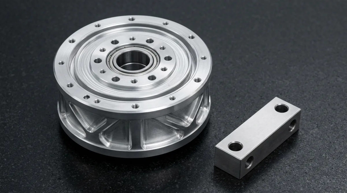
The image below showcases a finished monolithic robotic harmonic drive actuator housing in 7075-T651 aluminum following multi-stage precision CNC machining and stress-relief stabilization, highlighting the coordinate-bored bearing journal, concentric stator registers, and thin-walled exterior lattice ribs:
3. Shop-Floor Manufacturing Realities: 3/4-Axis VMC Workhorses vs. 5-Axis Precision
Overcoming the “5-axis only” marketing myth is essential for cost-effective hardware prototyping. While online discussions frequently suggest that modern robots are machined entirely on 5-axis simultaneous machining centers, actual shop-floor production realities in precision prototype shops demonstrate a far more pragmatic division of labor:
High-speed 3-axis and 4-axis vertical machining centers (VMCs) carry 75% to 85% of total machining capacity. Structural robot torso frames, AMR chassis baseplates, battery containment boxes, liquid cold plates, wheel hub knuckles, LiDAR sensor brackets, and structural crossbeams are predominantly prismatic components. Machining these parts on high-precision 3-axis or 4-axis VMCs (utilizing Brother, Haas, or Mazak platforms equipped with 15,000 to 24,000 RPM spindles) delivers maximum structural rigidity, superior surface finishes, faster setup turnaround, and significantly lower machining hourly costs.
Tooling setups rely on precision workholding systems:
Modular Zero-Point Tooling Plates: Pneumatic or mechanical zero-point quick-change receiver sub-plates allow rapid pallet swapping with sub-0.005 mm repositioning repeatability.
Precision Kurt Vises & Aluminum Soft Jaws: Machined 6061 aluminum soft jaws milled directly on the machine table cradle thin-walled or organic robot components, distributing clamping force evenly across delicate thin walls to prevent mechanical distortion upon release.
4-Axis Rotary Indexing Units: Equipped with precision direct-drive rotary tables, 4-axis setups enable 360° multi-sided prismatic milling, cross-hole drilling, and deep side-pocketing in a single clamping pass.
The Shop-Floor Fallacy of “5-Axis Roughing”: Why Production Shops Never Hog Billet on Multi-Axis Kinematics
A widespread misconception in rapid prototyping is the belief that 5-axis simultaneous machining centers should execute bulk material removal directly from raw billet stock. In professional precision machine shops, using continuous 5-axis motion for heavy roughing is an absolute engineering violation for three fundamental physical reasons:
Kinematic Compliance & Structural Rigidity Limits: Unlike rigid 3-axis VMCs or heavy Horizontal Machining Centers (HMCs) built on solid Meehanite cast-iron beds and preloaded roller linear or wide box guideways, 5-axis machines incorporate rotary trunnion tables (A/C axes) or articulating swivel heads (B/C axes). These rotary joints rely on cross-roller bearings, worm gear drives, or direct-drive torque motors. The dynamic stiffness (kdyn) of these rotary interfaces is inherently lower. Subjecting them to heavy bulk hogging induces mechanical deflection, chatter, and micro-vibration.
Rotary Bearing Shock Loads & Micro-Brinelling: Bulk roughing of dense aerospace 7075-T651 billets generates extreme interrupted cutting forces (Fc > 3,000 ∼ 6,000 N). Forcing these severe cyclic shock loads through rotary axis pivot bearings causes micro-brinelling of precision raceways, accelerated mechanical backlash degradation in rotary gearboxes, and thermal spindle distortion. This permanently destroys the machine’s ability to subsequently hold micron-level tolerances during finishing.
Spindle Hour Economics: A high-performance simultaneous 5-axis machining center commands an hourly operational rate 2.5x to 4x higher than a rigid 3-axis VMC. Wasting expensive 5-axis spindle hours on gross volumetric stock removal—where toolpaths represent simple prismatic clearing—drastically inflates prototyping costs without adding any geometric value.
The Mandatory Multi-Stage Process Routing for Monolithic Robotic Components
To produce flawless, stress-free robotic joint housings and articulated structural limbs while maintaining micron-level bearing seat tolerances, our facility enforces a strict multi-stage manufacturing protocol:
Stage 1 — Heavy Bulk Roughing on Rigid 3-Axis / HMC Workhorses: High-torque BT50 or heavy BT40 spindles with solid box ways execute gross material hogging. Using large-diameter indexable face mills (∅50 mm ∼ ∅63 mm) or solid carbide roughers (∅16 mm ∼ ∅20 mm) with high-efficiency dynamic trochoidal toolpaths (high axial depth ap ≥ 1.5D, small radial engagement ae = 8% ∼ 15%D), we remove 75% to 85% of excess billet material at maximum Metal Removal Rate (MRR). Crucially, a uniform 1.5 mm to 2.5 mm finishing allowance is left across all surfaces, with 0.8 mm left on primary datum faces.
Stage 2 — Complete Unclamping & Residual Stress Relief Rest: Even stretcher-stretched 7075-T651 billets store residual quench stresses. Bulk asymmetric metal removal releases internal bending moments (∫ σ(z) · z · dA ≠ 0). The workpiece is completely unclamped and released from all fixtures, resting freely on a Grade 00 granite plate for 12 to 24 hours, or undergoing alloy-specific thermal stabilization soaking (strictly ≤ 100°C ∼ 110°C for 7075-T651 to stay safely below its 120°C T6 precipitation aging threshold and prevent yield strength loss, or 150°C ∼ 165°C for 6061-T6). Any inherent material warp (“banana bowing”) occurs freely and stabilizes before finish machining.
Stage 3 — Semi-Finishing & Primary Datum Trueing (3-Axis / 3+2 Locked Setup): The stabilized workpiece is lightly re-clamped using custom aluminum soft jaws or modular vacuum chucks to prevent inducing mechanical clamping strains. The primary mounting face (Datum A) is precision fly-cut flat to within 0.005 mm. Pockets, mounting bosses, and rough bores are semi-finished, leaving a strictly uniform 0.20 mm to 0.30 mm finish allowance for final passes. This uniform stock ensures that subsequent finishing tools encounter constant, minimal cutting resistance.
Stage 4 — Simultaneous 5-Axis Precision Finishing (Finishing ONLY): Now, and only now, the part moves to a high-speed 5-axis machining center (18,000 ∼ 24,000 RPM high-frequency electric spindle, HSK-63A dual-contact toolholder dynamically balanced to G2.5). Utilizing RTCP / TCPM dynamic vector tracking at >1 kHz, solid carbide ball-end mills (∅4 mm ∼ ∅8 mm) or circle-segment barrel cutters (Reff = 250 ∼ 500 mm) sweep organic skeletal curvatures, deep undercut profiles, and blended joint fillets. Toolpaths maintain a continuous 15° to 25° lead/tilt angle relative to the surface normal to eliminate the apex dead-zone (where center cutting velocity vc = 0 m/min), achieving high peripheral shearing speed, mirror-like Ra ≤ 0.4 μm surface finish, and seamless transitions without tool mismatch steps. Cutting forces are minimal (Fc < 50 ∼ 80 N), completely protecting the 5-axis rotary table bearings.
Stage 5 — Thin-Wall Step-Down Waterline Strategy: When machining skeletal ribs and web pockets down to 0.8 mm to 1.2 mm thickness, tools execute synchronized incremental Z-level waterline passes. The lower un-machined solid core serves as a rigid backing support while finishing the upper rib segments, completely suppressing thin-wall cantilever deflection, high-frequency resonance, and edge chatter.
Stage 6 — Single-Setup Coordinate Micro-Boring with Mechanically Locked Rotary Axes: For critical motor stator bores, harmonic drive pilot registers, and bearing seats (ISO H7/g6, concentricity ≤ 0.008 mm), the machine’s A/C rotary axes are hydraulically locked by high-torque disc brakes (> 2,000 N·m), freezing all angular degrees of freedom. Digital micro-boring heads (with 0.002 mm vernier resolution) execute rigid Z-axis line-boring in a single setup, guaranteeing bearing bore concentricity within ≤ 0.006 mm and coaxiality within ≤ 0.008 mm.
Stage 7 — Zeiss Bridge CMM Dimensional Verification (Available Upon Request): After post-machining cleaning and thermal equalization in our 20.0°C ±0.5°C climate-controlled metrology lab, continuous-scanning ruby probe heads verify all GD&T datum frameworks.
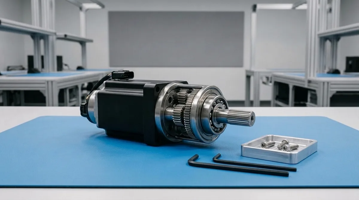
The image below illustrates the subassembly of a precision robotic joint and arm mechanism on our clean assembly workbench, highlighting the integration of multi-axis machined aluminum housings, precision drive shafts, and high-ratio planetary reduction stages:
Precision robotic actuator joint subassembly on clean ESD workbench mat, integrating a satin black-anodized 7075 motor shell, multi-stage planetary gearset, ground splined shaft, and cross-roller bearing.
Achieving optimal mechatronic performance requires rigorous geometric dimensioning and tolerancing (GD&T) budgeting. In high-torque frameless motor actuators, the air gap between the rotating permanent magnet rotor and the stationary laminated iron stator core is typically only 0.25 mm to 0.40 mm. Any radial runout, bore taper, or thermal distortion in the actuator housing can cause rotor-stator rub, resulting in catastrophic motor destruction.
Stator press-fit interference calculations and thermal expansion: Frameless BLDC motor stators are generally retained in the aluminum joint housing via an engineered interference fit (ISO H7/m6 or H7/k5). When calculating the room-temperature interference allowance, engineers must account for differential thermal expansion between the aluminum housing and the silicon steel stator stack. The linear thermal expansion equation governs dimensional drift:
ΔD = D0 · α · ΔT
Differential coefficient of thermal expansion (Δα): Aircraft-grade 7075-T6 aluminum exhibits a coefficient of thermal expansion of αAl ≈ 23.4 × 10⁻⁶ / K, whereas laminated electrical silicon steel has αSteel ≈ 12.0 × 10⁻⁶ / K. Over a 60°C operating temperature rise (20°C ambient to 80°C continuous motor winding operation), an 80 mm diameter housing bore expands by approximately 0.112 mm, while the stator stack expands by only 0.058 mm. The differential thermal expansion of approximately 0.054 mm will completely relieve a light interference press-fit, allowing the stator to spin inside the housing. Our engineering team calculates exact thermal interference budgets, often incorporating auxiliary radial locking keys, retaining flanges, or thermal shrink-fit assembly protocols (chilling stators in liquid nitrogen while heating housings to 120°C).
Precision wire electrical discharge machining (EDM) for splines and keyways: Miniature robot motor drive shafts and anti-backlash torque couplers feature high-precision involute splines (conforming to DIN 5480 or ANSI B92.1) and miniature keyways. Utilizing fine-wire EDM with 0.10 mm to 0.20 mm brass wire, we achieve spline tooth flank profiles with cumulative pitch errors within ±0.005 mm (±0.0002″) and root radii down to R 0.05 mm, completely eliminating backlash in reversible drive trains.
Table 1: Robotics Actuator Housing GD&T Tolerancing & Fit Budget
Functional Feature
Nominal Dimension
Tolerance / ISO Fit
GD&T Control
Shop-Floor Tooling Protocol
Engineering Purpose
Motor Stator Bore
∅60 mm ∼ ∅120 mm
ISO H7 (+0.030 / +0.000 mm)
Cylindricity ≤ 0.006 mm; Runout ≤ 0.008 mm
Precision single-point coordinate boring head
Prevents stator spinning under torque while maintaining air gap
Angular Contact Bearing Seats
∅35 mm ∼ ∅90 mm
ISO JS6 / H7 (±0.008 to ±0.012 mm)
Coaxiality ≤ 0.006 mm; Perpendicularity ≤ 0.005 mm
Line-bored in single setup with balanced boring bar
Eliminates bearing pinching, excessive preload drag, and thermal binding
Harmonic Reducer Pilot Bore
∅50 mm ∼ ∅110 mm
ISO H7 (+0.030 / +0.000 mm)
True Position ∅0.008 mm relative to Datum A
Robotics material selection is a multidimensional trade-off between strength, mass density, thermal conductivity, and machinability. No single material fulfills all requirements across a complete robot architecture. Our engineering team selects specialized alloys and engineered substrates based on functional subsystem demands:
7075-T651 Aluminum (Al-Zn-Mg-Cu Alloy): The undisputed gold standard for primary structural robot limbs, humanoid pelvic frames, and high-torque joint shells. Stress-relieved stretcher-stretched billet (T651 temper) provides yield strength approaching 503 MPa—surpassing structural mild steel—with a low density of 2.81 g/cm3. Stress relief ensures that aggressive pocketing does not induce warp or post-machining dimensional creep.
6061-T6 Aluminum (Al-Mg-Si Alloy): Preferred for structural baseplates, AMR chassis weldments, electronics mounting trays, and liquid cold plates. Offers excellent corrosion resistance, superior thermal conductivity (k ≈ 167 W/m·K), and excellent weldability. Easily accepts decorative and protective anodized finishes.
Titanium Grade 5 (Ti-6Al-4V): Deployed in high-load, high-impact robotic zones, such as humanoid foot arches, ankle universal joints, robotic dog knee linkages, and wrist output spindles. With yield strength ≥ 880 MPa and an exceptional strength-to-weight ratio, titanium withstands heavy shock loads without fatigue cracking, though it requires rigid CNC tooling, low cutting speeds, and high-pressure flood coolant.
17-4PH Stainless Steel (Condition H900 / H1025): Precipitation-hardening martensitic stainless steel utilized for high-torque splined shafts, planetary sun gears, and cycloidal eccentric cams. Condition H900 delivers hardness up to 44 HRC and yield strength ≥ 1,170 MPa with minimal heat-treat dimensional distortion.
Carbon Fiber Composites (3K CFRP Plates & Hybrid Tube Nodes): Autoclave-cured 3K carbon fiber plates (2.0 mm to 10.0 mm thickness) CNC-routed with diamond-coated compression cutters into lightweight drone frames and robot side-plates, alongside precision CNC-machined 7075-T651 aluminum end-lugs, clevises, and bonding collars designed to mate with commercial roll-wrapped carbon fiber arm tubes.
Engineering Polymers (Victrex PEEK & POM-C): Polyetheretherketone (PEEK-450G) and polyoxymethylene (Delrin / POM-C) are CNC machined into low-friction bushings, isolated encoder mounting rings, sensor housings, and compliant gripper fingertips, providing self-lubrication, zero magnetic interference, and electrical insulation.
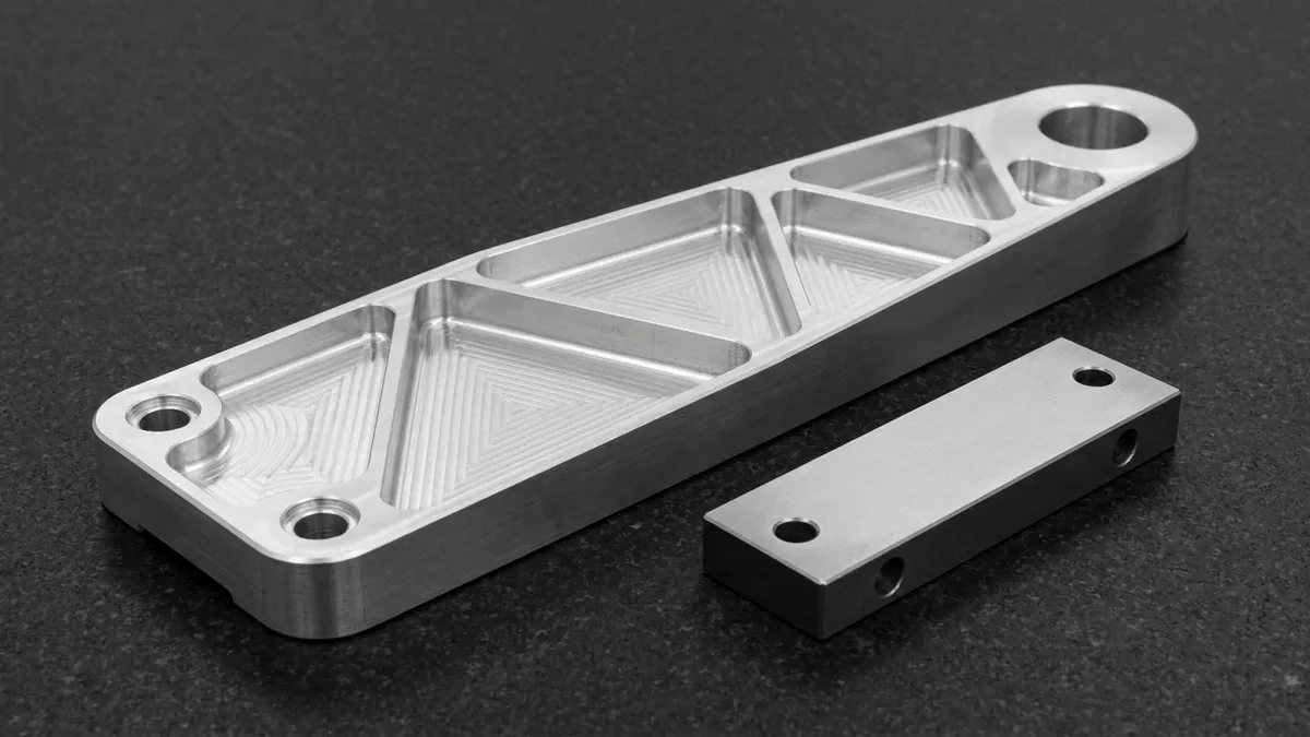
The image below showcases a monolithic CNC-machined aerospace-grade 7075-T651 aluminum bipedal robotic leg link and knee joint clevis resting on our metrology inspection plate, highlighting deep triangular isogrid pockets with 1.0 mm thin walls, precision-reamed bearing pivot bores, and crisp 0.2 mm edge chamfers:
Monolithic CNC-machined 7075-T651 aluminum robotic arm link resting 100% flat on its planar datum face, displaying deep triangular isogrid pockets with 1.0 mm thin walls and precision-reamed pivot bores.
Table 2: Material Selection Matrix for Robotic Subsystems
Material Substrate
Density (ρ)
Yield Strength (σy)
Elastic Modulus (E)
Thermal Cond. (k)
Machinability Index
Typical Robotic Hardware Domain
7075-T651 Billet Al
2.81 g/cm3
503 MPa
71.7 GPa
130 W/m·K
High (70%)
Joint actuator housings, robotic arm skeletal links, gear hubs
6061-T6 Plate Al
2.70 g/cm3
276 MPa
68.9 GPa
167 W/m·K
Very High (90%)
AMR baseplates, battery enclosures, heatsink cold plates
Thermal throttling is the silent killer of mobile robotics performance. When high-torque frameless BLDC motors operate under sustained stall or cyclic dynamic acceleration, resistive I2R copper winding losses and eddy current losses generate intense heat within compact joint volumes. Without a dedicated thermal dissipation architecture, winding temperatures rapidly climb beyond 130°C, triggering motor controller torque derating, thermal demagnetization of NdFeB permanent magnets, and degradation of bearing grease.
Conduction thermal modeling across the actuator housing: Heat generated in the stator core must conduct outward across the aluminum housing walls to ambient air. One-dimensional conductive heat flux is governed by Fourier’s law:
q = -k · A · (dT / dx)
Thermal interface resistance mitigation: Because 7075-T6 provides a thermal conductivity of k ≈ 130 W/m·K, the metallic housing wall exhibits minimal thermal resistance (Rcond < 0.05 K/W). The primary thermal bottleneck occurs at the mechanical interface between the stator core and the housing bore, where microscopic surface roughness introduces air micro-gaps. By coordinate-boring the stator bore to a fine surface finish of Ra ≤ 0.4 μm and applying high-conductivity thermal interface compounds (such as Wakefield-Vette or DOW TC-5026 with k ≥ 3.0 W/m·K), interface thermal resistance is slashed by over 65%. For high-duty-cycle actuators, we integrate external micro-convective cooling fins directly into the 5-axis CNC toolpaths, expanding effective convective surface area by up to 220%.
Ingress protection engineering (IP65 / IP67 environmental sealing): Field robotics platforms must operate reliably in rainy outdoor environments, dusty construction sites, and washdown factory floors. Achieving robust IP65 or IP67 sealing across high-speed articulating joints requires rigorous sealing groove design:
Rotary Dynamic Seals: Articulated joint outputs employ precision PTFE lip seals or dual FKM (Viton) rotary shaft seals. The mating shaft sealing land is ground and polished to a mirror finish of Ra 0.2 μm with zero lead (zero machine spiral markings), preventing capillary oil leakage or moisture ingress during bi-directional rotation.
Static O-Ring Grooves: Machined in housing face flanges and cable gland ports conforming to ISO 3601-2 standards. We enforce tight groove depth tolerances (±0.02 mm), full radiused bottom corners (R 0.2 mm ∼ 0.4 mm) to prevent notch stress concentration, and side-wall surface roughness Ra ≤ 0.8 μm to ensure 20% to 30% controlled elastomer compression without pinching.
Internal Cable Passages: High-speed EtherCAT, CAN-FD, and 48V power lines routing through joint centers are protected by fully chamfered, deburred internal passages. All internal wire pathways are polished to remove sharp machining burrs, eliminating insulation chafing during continuous ±360° joint rotation.
Surface finish engineering for robotics hardware:
MIL-A-8625 Type III Hardcoat Anodizing: 40 μm to 50 μm thickness with PTFE impregnation. Applied to external aluminum housings and bearing sliding registers to provide exceptional surface hardness (450 to 550 HV) and superior wear resistance against environmental abrasion.
MIL-DTL-5541 Type II Class 3 Chemical Conversion Coating (Clear Chem Film / Alodine): Applied to internal motor cavity registers and electrical grounding bosses. Chem film maintains low electrical contact resistance (< 5 mΩ), ensuring robust EMI shielding continuity across the housing while protecting raw aluminum against atmospheric corrosion.
Electroless Nickel Plating (MIL-C-26074): 15 μm to 25 μm uniform coating applied to alloy steel drive shafts and cycloidal pins, providing 50 to 52 HRC hardness and outstanding resistance against moisture corrosion and friction galling.
Prototyping a complete autonomous robotic platform requires coordinating multiple manufacturing technologies across structural frames, drive trains, sensory fairings, and end-effectors. The matrix below outlines the manufacturing processes, recommended substrate materials, critical engineering tolerances, and standard ex-factory prototyping turnaround times across core robotics subsystems:
Next-generation bipedal humanoids require micro-mechanical precision alongside heavy structural load capacity. While torso and hip rotary joints scale from collaborative robot architectures, humanoid platforms introduce three specialized mechanical sub-assemblies that frequently bottleneck hardware validation: multi-DoF anthropomorphic dexterous hands, high-thrust linear leg actuators, and ultra-lightweight lower-limb structural frames.
8.1 Robotic Dexterous Hand Micro-Linkages, Phalanges & Tendon Routing Pulleys
Anthropomorphic robotic hands pack 12 to 22 degrees of freedom (DoF) into the volume of a human palm. Whether driven by palm-mounted coreless micro-motors with planetary/worm stages, miniature four-bar linkages, or high-modulus UHMWPE (Dyneema) / tungsten Bowden tendons, machining errors of just ±0.015 mm across serial finger phalanges compound into severe fingertip hysteresis and grasp instability.
Swiss-Type CNC Sliding-Headstock Micro-Turning: Miniature pivot dowel pins (Ø1.0 mm to Ø4.0 mm), lead-screw spindles, and micro worm shafts are machined on Swiss-type CNC lathes where the bar stock is supported within 1.5 mm of the single-point carbide tool by a synchronized guide bushing. This eliminates cantilever deflection on slender shafts (L/D ratios up to 20:1), holding journal diameters to ±0.005 mm (±0.0002″, ISO h5/g6) and concentricity within ≤ 0.005 mm.
Tendon Sheave Groove Geometry & Tribology: In tendon-driven dexterous hands, premature tendon snap is almost always caused by microscopic machining burrs or tool feed lines inside redirection pulleys. We machine pulley groove radii to Rgroove = 0.53 ∼ 0.55 · dtendon with a 45° flared entry angle and polish the contact track to a mirror finish of Ra ≤ 0.2 μm (8 μin) in 17-4PH H900 stainless steel or PVD DLC-coated Ti-6Al-4V, extending tendon cyclic fatigue life by over 400%.
Self-Lubricating Gear & Bushing Pairs: Micro bevel and worm gear pairs combine hardened 17-4PH or 4140 steel worms with C3604 brass or carbon-fiber-reinforced PEEK (PEEK-CF30) wheels to suppress stick-slip friction during low-speed force-controlled grasping.
Bipedal humanoid knees and ankles increasingly replace bulky rotary gearboxes with high-force linear actuators driven by inverted planetary roller screws or precision ball screws arranged in parallel four-bar or Stewart-platform linkages. During dynamic walking, running, and jump-landing recovery, these linear shafts endure high axial shock loads combined with side-loading moments.
Euler buckling and straightness govern linear actuator survival. Under peak compressive thrust (Faxial), a slender actuator piston rod or linear guide shaft must resist elastic buckling governed by Euler’s critical load equation:
Pcr = (π2 · E · I) / (K · L)2
Any geometric bow or cylindricity runout introduces an initial eccentricity (e0) that triggers second-order bending magnification (the secant formula) and jams the roller nut. To guarantee zero-binding linear motion:
Alloy Selection & Induction Case Hardening: Linear shafts and piston rods are turned from vacuum-degassed 42CrMo4 (AISI 4140) or 440C martensitic stainless steel, followed by high-frequency induction hardening (case depth 0.8–1.5 mm at 58–62 HRC) while preserving a tough, ductile core (30–34 HRC) to absorb heel-strike impact shock.
Centerless & Between-Centers Cylindrical Grinding: Post-heat-treatment distortion is removed via precision cylindrical grinding between dead centers, achieving diameter tolerances of ISO g6 / h5 (±0.004 to ±0.006 mm), circularity ≤ 0.003 mm, and straightness within ≤ 0.005 mm per 100 mm (0.0002″/4″).
Hollow Shaft Weight Reduction: Because bending stiffness scales with the fourth power of diameter — I = π · (Do4 − Di4) / 64 — gun-drilling a central bore equal to Di = 0.6 · Do removes 36% of shaft mass while retaining 87% of torsional and buckling stiffness, simultaneously providing a central conduit for internal force-torque sensor wiring.
Monolithic femur, tibia, and pelvis structural frames demand aggressive weight removal without sacrificing joint datum alignment. As detailed in our 6061 vs. 7075 aluminum selection guide, replacing 6061-T6 with aerospace 7075-T651 allows wall thicknesses in pocketed isogrid limb struts to be reduced from 2.2 mm to 1.2 mm while maintaining identical yield safety factors. For ultra-thin rotational bearing sleeves and sensor rings, we apply specialized piezo-damped tooling and custom expanding mandrels documented in our thin-wall aluminum CNC turning case study. Meanwhile, humanoid stereo-vision and LiDAR head gimbals are CNC-milled from 6061-T6 and finished with optical-black MIL-A-8625 Type II Class 2 matte anodizing to eliminate stray near-infrared (850 nm / 905 nm / 940 nm) internal reflections across depth-camera optical paths.
In high-degree-of-freedom (DoF) kinematic chains, microscopic machining errors compound geometrically. In an articulated 6-DoF or 7-DoF robotic manipulator, a minuscule angular error of 0.015° (due to an out-of-square bearing bore at Joint 1) translates into several millimeters of kinematic positioning error at the robot’s end-effector. Sub-assembly metrology and rigorous geometric validation are therefore critical prior to mechanical integration.
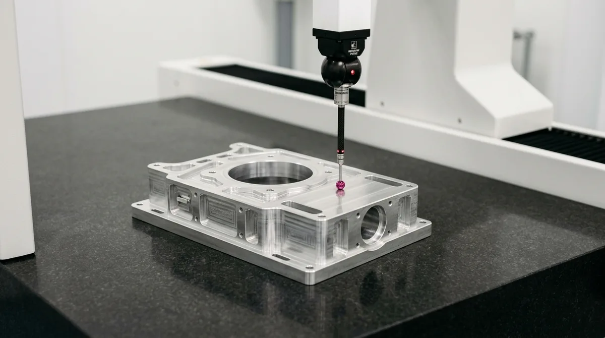
The image below captures the quality inspection of an articulated robotic arm link on our bridge coordinate measuring machine (CMM), where a motorized Renishaw scanning probe verifies bearing seat true position, cylindricity, and datum alignment:
Zeiss bridge coordinate measuring machine (CMM) continuous scanning: Motorized ruby probe softly touches top flat Datum A mounting plane in 360-degree open air, verifying sub-micron flatness and journal true position.
Bridge CMM Coordinate Inspection (Available Upon Request): Utilizing calibrated Zeiss bridge CMMs in our 20.0°C ±1.0°C temperature-controlled metrology room, we verify bearing seat cylindricity, opposing bore coaxiality, pilot perpendicularity, and ASME Y14.5-2018 Datum A-B-C true position relationships.
3-Point Internal Bore Micrometers & Calibrated Go/No-Go Gauges: Every ISO H7/JS6 bearing seat and precision-reamed dowel pin hole is inspected directly at the machine and in final QC using 0.001 mm resolution 3-point internal bore micrometers (Mitutoyo Holtest) and calibrated Class Z/X Go/No-Go plug and thread gauges.
Granite Surface Plate, Dial Test Indicator (DTI) & Trial Bearing Fit Verification: Long structural humanoid femur/tibia links and AMR baseplates are inspected on Grade 00 granite surface plates using lever-type dial test indicators (0.002 mm graduation) and precision height gauges to confirm datum flatness (≤ 0.020 mm). When reference bearings or mating shafts are supplied, our QC technicians perform physical trial fit-checks to confirm smooth, zero-binding seating prior to shipment.
Surface Roughness & Hardness Verification: Contact stylus profilometers verify critical bearing journals and dynamic rotary seal lands against ISO 4287 / ASME B46.1 standards (Ra ≤ 0.4 μm / 16 μin for fine-bored seats; Ra ≤ 0.2 μm / 8 μin for ground/polished seal lands). Rockwell (ASTM E18) and Vickers (ASTM E384) hardness testers verify heat-treated steel shafts and MIL-A-8625 Type III hardcoat anodizing layers.
During robotics prototyping, hardware teams often encounter unexpected mechanical failure modes during initial bench testing. The following troubleshooting guide outlines the root causes and shop-floor corrective actions developed by our precision machining engineering team:
Issue 1: Joint Binding & Severe Motor Cogging After Actuator Assembly
Symptom: The actuator exhibits high rotational drag torque, severe torque ripple, or mechanical lockup when motor phase leads are unpowered.
Root Cause Analysis: Non-coaxial bearing seats. When bearing journals on opposite housing halves are machined across multiple setups or clamping orientations, cumulative fixture error introduces an angular tilt (> 0.020°). When the joint is torqued together, the rigid outer rings of deep-groove or angular-contact bearings pinch the rolling balls, causing excessive internal preloading and binding.
Corrective Engineering Action: Line-bore both bearing seats in a single setup on a multi-axis machining center. If two mating halves are required, incorporate hardened locating dowel pins (conforming to ISO 8734) with precision-reamed holes (±0.005 mm) to enforce sub-0.006 mm coaxial alignment across housing halves.
Symptom: Rapid degradation of harmonic drive reduction ratio accuracy, audible clicking during high-speed reversal, or fatigue fracture along the flexspline diaphragm.
Root Cause Analysis: Radial runout between the motor shaft output and the harmonic wave generator pilot bore exceeding 0.010 mm. This eccentricity forces the elliptical wave generator to mesh asymmetrical gear teeth with unequal contact stress, concentrating cyclic bending fatigue along one quadrant of the thin flexspline cup.
Corrective Engineering Action: Enforce a true position tolerance of ∅0.008 mm (MMC) on the circular spline mounting register relative to the primary bearing journal. Precision wire EDM the motor shaft spline with cumulative pitch error ≤ 0.003 mm to ensure perfectly centered torque transfer.
Issue 3: High-Frequency Resonance & Trajectory Overshoot During High-Acceleration Moves
Symptom: Robot end-effector oscillates upon completing rapid point-to-point moves, requiring prolonged settling time or aggressive control gain derating.
Root Cause Analysis: Inadequate first natural resonance frequency (fn) caused by structural limb compliance and excessive distal weight. Solid aluminum links add mass without contributing proportional stiffness at distal joints.
Corrective Engineering Action: Redesign distal structural limbs using closed-box isogrid pocketing in 7075-T651 aluminum or hybrid roll-wrapped carbon fiber composite tubes with CNC-machined 7075 end nodes. This raises the first structural resonance frequency fn = (1 / 2π) √(k / m) well beyond the control loop’s closed-loop bandwidth (> 60 Hz), eliminating structural vibration.
What are the critical machining tolerances required for robotic harmonic drive and cycloidal actuator housings?
High-performance robotic harmonic and cycloidal drive housings require CNC fine-bored aluminum bearing seat and pilot register tolerances of ISO H7 / JS6 (±0.008 to ±0.012 mm / ±0.0003″ to ±0.0005″), bore cylindricity ≤ 0.008 mm, and face perpendicularity ≤ 0.008 mm relative to the primary rotational datum, while hardened steel shafts and Wire-EDM splines are held to ±0.005 mm (±0.0002″). Coaxiality across opposing bearing journals is maintained within ≤ 0.010 mm. To achieve these tight GD&T controls, our machine shop executes single-setup coordinate boring on multi-axis CNC machining centers, completely eliminating cumulative fixture repositioning errors.
Why is 7075-T651 aluminum preferred over 6061-T6 for high-torque robotic limbs and joint shells?
7075-T651 delivers nearly double the yield strength of 6061-T6 (≈ 503 MPa vs. 276 MPa) at virtually identical mass density (2.81 g/cm3 vs. 2.70 g/cm3), providing an exceptional strength-to-weight ratio. The stress-relieved T651 temper ensures that heavy CNC pocketing and thin-wall milling (down to 1.0 mm) can be executed without inducing internal stress relaxation, warping, or dimensional distortion across critical bearing journals.
How do you prevent thermal runaway and motor slippage in compact robotic actuators?
We engineer motor stator housings with precise ISO H7/m6 interference press-fits, accounting for the differential thermal expansion between aluminum (23.4 × 10⁻⁶ / K) and silicon electrical steel (12.0 × 10⁻⁶ / K). By coordinate-boring the stator cavity to Ra ≤ 0.4 μm and applying high-conductivity thermal interface compounds, we minimize interfacial thermal resistance. External micro-convective cooling fins are machined directly into the housing exterior to expand convective heat dissipation, preventing winding temperatures from exceeding 110°C during continuous stall torque.
What is the shop-floor division of labor between 3/4-axis VMCs and simultaneous 5-axis CNC machining in robotics prototyping?
Production machine shops strictly divide operations: rigid 3-axis VMCs or HMCs perform 100% of heavy bulk roughing (removing 75% to 85% of billet material at maximum MRR) to protect machine kinematics and reduce spindle costs. Following complete unclamping for residual stress relief and semi-finishing, simultaneous 5-axis CNC machining is deployed exclusively for high-speed finishing of complex organic contours, multi-axis blended transitions, and thin-wall skeletal webs where continuous tool tilting eliminates apex dead-zones.
What surface treatments provide both wear resistance and EMI shielding for robotic joint housings?
We deploy a dual surface engineering approach: external surfaces and bearing registers receive MIL-A-8625 Type III Class 1 or 2 Hardcoat Anodizing (40 to 50 μm, 450 to 550 HV) with optional PTFE impregnation, providing superior hardness and abrasion protection. Meanwhile, internal motor pockets, encoder cavities, and grounding pads receive MIL-DTL-5541 Type II Class 3 Clear Chem Film (Alodine / SurTec 650), preserving low electrical contact resistance (< 5 mΩ) to ensure continuous Faraday-cage EMI shielding across the robot assembly.
How do you machine miniature robotic dexterous hand linkages, micro-shafts, and tendon pulleys without cable fraying?
We machine Ø1.0 to Ø6.0 mm pivot pins, worm shafts, and micro-bushings on CNC Swiss-type sliding-headstock lathes, holding ±0.005 mm (±0.0002″, ISO h5/g6) diameter tolerances across slender shafts. For tendon-driven dexterous hands, pulley grooves are contoured to R = 0.53–0.55 × tendon diameter and mirror-polished to Ra ≤ 0.2 μm (8 μin) with optional PVD DLC low-friction coating, eliminating sharp edges that cause UHMWPE or stainless steel Bowden tendon fatigue.
What straightness and hardness specs are required for humanoid robot linear actuator shafts?
Bipedal knee and ankle linear actuator shafts require induction-hardened 42CrMo4 (AISI 4140) or 440C stainless steel heat-treated to 58–62 HRC case hardness over a tough 30–34 HRC core. Following heat treatment, shafts are precision ground between centers to ISO g6/h5 journal tolerances, holding straightness within ≤ 0.005 mm per 100 mm and surface roughness to Ra 0.1–0.2 μm (4–8 μin) to prevent planetary roller-screw binding under dynamic gait impact.
Accelerate Your Robotics Platform from CAD to Field Reality
From high-torque actuator housings and harmonic drive spline couplers to bipedal humanoid skeletons, AMR chasses, and lightweight carbon limbs, AS Prototypes delivers the precision CNC machining, rapid tooling, and GD&T metrology your robotics hardware demands.