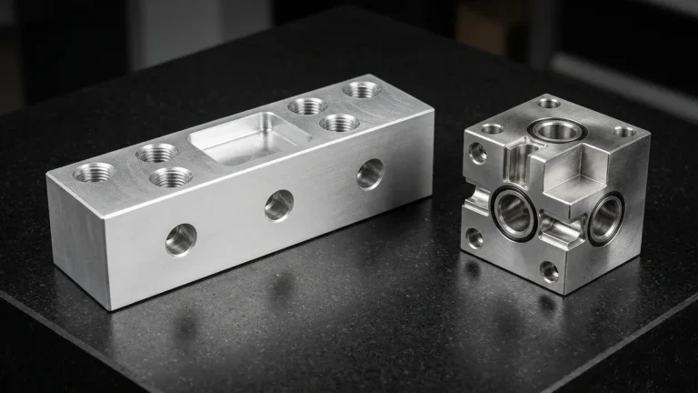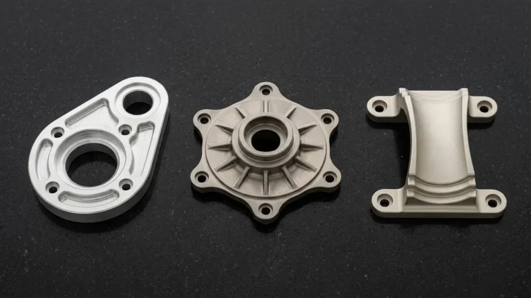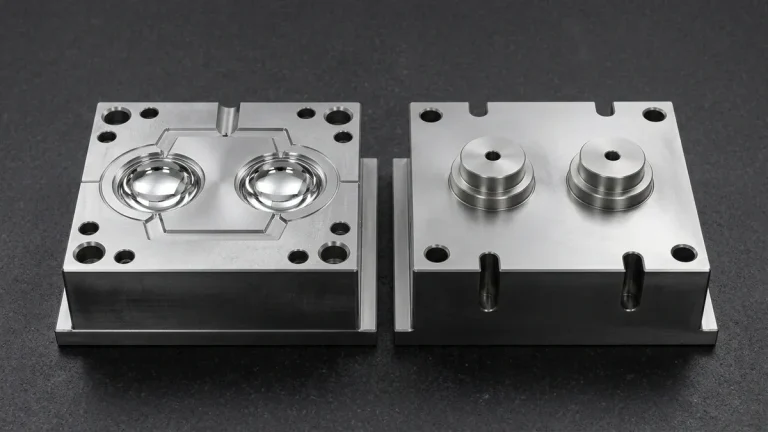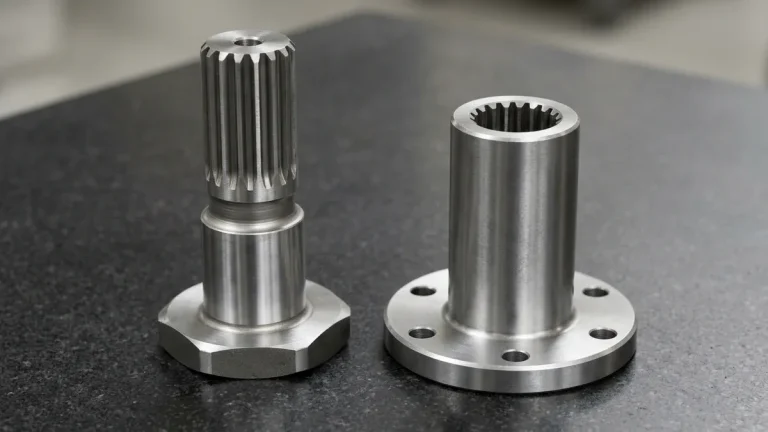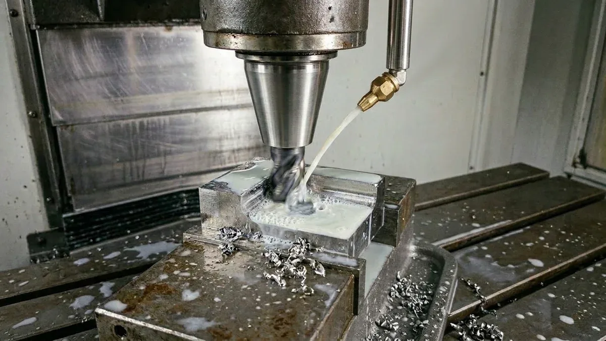
In modern subtractive manufacturing, vertical walls, stepped shoulders, deep slots, and external profiles constitute the geometric backbone of prismatic mechanical engineering. Whether fabricating aerospace bulkhead brackets, semiconductor vacuum chambers, or precision optical housings, generating perfectly flat, vertical, and square sidewalls depends fundamentally on side milling in CNC machining.
Unlike face milling—where cutting action occurs predominantly on the flat bottom face of the cutter perpendicular to the spindle axis—side milling utilizes the cylindrical peripheral teeth of a milling cutter to shear away material along a vertical or angular workpiece plane. While intuitively straightforward, achieving micron-level wall straightness, high perpendicularity, and optical surface finishes during side milling requires deep mastery of cutting mechanics, radial chip thinning, tool deflection dynamics, and harmonic vibration damping.
At AS Prototypes, our CNC milling centers execute thousands of complex side milling operations daily across tough superalloys, structural steels, engineering plastics, and aerospace aluminum alloys. Below is our engineering master guide detailing side milling kinematics, cutting parameter governing equations, tooling configurations, deflection mitigation strategies, and practical DFM guidelines.
- 1. What is Side Milling? Kinematics & Geometric Definition
- 2. Core Governing Equations & Cutting Mechanics
- 3. Types of Side Milling Operations
- 4. Tool Deflection Mechanics: The Physics of Wall Taper
- 5. Climb Milling vs. Conventional Milling in Side Milling Operations
- 6. Deflection Compensation & Precision Wall Finishing Strategies
- 7. Engineering Case Study: Avionics Datum Wall Perpendicularity
- 8. Design for Manufacturability (DFM) Rules for Side Milling
- 9. Technical Engineering FAQ
1. What is Side Milling? Kinematics & Geometric Definition
Side milling (frequently referred to as peripheral milling or profile milling) is defined as a machining operation where the peripheral cutting edges located along the tool’s cylindrical circumference generate a machined surface parallel to the tool’s rotational axis (Z-axis):
- Engagement Mechanics: The primary cutting action is performed by the helical flutes on the cutter’s periphery. The axial depth of cut (ap) spans along the tool’s length, while the radial depth of cut (ae, or width of cut) represents the engagement width into the uncut workpiece flank.
- Force Distribution: Unlike face milling where cutting forces are largely axial and directed into the rigid machine spindle, side milling generates substantial radial cutting forces (Fr) that push laterally against both the tool assembly and the workpiece wall. Managing these lateral vectors is the central challenge in achieving tight geometric tolerances.
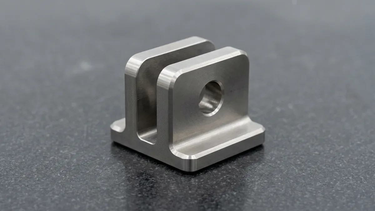
- Shoulder & Step Generation: When a 90° square shoulder end mill or indexable cutter is used, side milling simultaneously finishes a vertical sidewall with its peripheral flutes and a perpendicular horizontal floor with its bottom end flutes, forming an exact 90° step.
2. Core Governing Equations & Cutting Mechanics
Precise CAM programming and process planning require rigorous mathematical modeling rather than guesswork. The fundamental parameters governing side milling performance include:
1. Spindle Speed & Cutting Speed
The tangential peripheral velocity of the tool’s cutting edges is expressed as:
Vc = π · D · n / 1000 ⇔ n = (1000 · Vc) / (π · D)
Where Vc is cutting speed in meters per minute (m/min), D is cutter diameter in millimeters (mm), and n is spindle rotational speed in revolutions per minute (RPM).
2. Table Feed Rate & Feed per Tooth
Linear feed velocity along the contour is calculated by:
Vf = fz · z · n
Where Vf is table feed speed (mm/min), fz is feed per tooth (mm/tooth), z is the number of active flutes, and n is spindle speed (RPM).
3. Radial Chip Thinning Factor (RCTF) Compensation
When performing finishing side milling passes where radial engagement is small (ae < D / 2), the actual maximum chip thickness (hmax) sheared by the cutter is significantly smaller than the programmed nominal feed per tooth (fz). Mathematically:
hmax = 2 · fz · √((ae / D) · (1 − ae / D)) ≈ 2 · fz · √(ae / D)
If an engineer programs a standard finish pass with ae = 0.05 · D and fails to compensate, the true chip thickness drops by more than 56% (2 · √(0.05 × 0.95) ≈ 0.436). The cutting edge rubs and plows rather than cleanly shearing the material, causing rapid work-hardening, severe heat buildup, and premature tool dulling. To maintain the optimal target chip thickness (htarget), the programmed feed per tooth must be compensated:
fz,compensated = htarget / (2 · √((ae / D) · (1 − ae / D))) ≈ htarget / (2 · √(ae / D))
4. Material Removal Rate (MRR)
Overall volumetric productivity during side milling roughing is quantified by:
MRR = (ap · ae · Vf) / (1000) (cm3/min)
3. Types of Side Milling Operations
Depending on part geometry, machine spindle orientation, and tooling architecture, side milling is implemented in five distinct technical configurations:
1. Plain (Slab) Side Milling
Utilized primarily on horizontal milling machines with arbor-mounted cylindrical cutters (helical slab mills). The cutting teeth shear along wide vertical or horizontal planes. Helical cutting edges ensure that cutting loads engage progressively, avoiding shock impulses.
2. Shoulder Milling (Square 90° Profiling)
The most ubiquitous operation on 3-axis and 5-axis vertical machining centers. Utilizing solid carbide square end mills or indexable 90° shoulder cutters, the tool machines a vertical wall while maintaining an exact 90° corner with the bottom floor.
3. Side-and-Face Milling (Slotting & Grooving)
Employs disc-type milling cutters that feature cutting teeth on both cylindrical sides as well as the outer circumference. Often designed with staggered teeth (alternating left-hand and right-hand helical shear angles), side-and-face cutters balance lateral thrust forces, allowing deep, narrow keyways, T-slots, and deep pockets to be machined without chip jamming or cutter pinching.
4. Straddle Milling
An exceptionally productive horizontal machining strategy where two identical side milling disc cutters are mounted on a common arbor, spaced apart by precision ground spacer collars. The arbor straddles the workpiece, machining two external parallel vertical faces in a single pass. This guarantees absolute parallelism and exact span thickness in high-volume production runs.
5. Angular Side Milling & Form Contouring
Performs side cuts where the cutting edge is angled relative to the workpiece coordinate system (e.g., machining 30°, 45°, or 60° dovetail slides, bevels, or chamfers). When executed on 5-axis CNC machining centers, tool center point management (TCPM) continuously swivels the tool flank tangent to complex freeform aerodynamic or hydrodynamic surfaces (flank milling).
4. Tool Deflection Mechanics: The Physics of Wall Taper
The foremost quality issue encountered in precision side milling is wall taper (out-of-squareness). Because the cutting tool acts as a cantilever beam rigidly clamped in the toolholder, lateral radial cutting forces (Fr) induce elastic bending deflection (δ):
δ = (Fr · L3) / (3 · E · I) where I = (π · d4) / (64)
Substituting area moment of inertia I demonstrates the critical relationship:
δ ∝ (Fr · L3) / (E · d4)
Where L is tool stickout (overhang length) from the holder nose, d is core tool diameter, and E is Young’s modulus of the tool substrate (solid tungsten carbide ≈ 600 GPa vs high-speed steel ≈ 210 GPa).
Crucial Engineering Insights:
- The Cubic Overhang Penalty (L3): Increasing tool overhang from 3D to 5D increases deflection by a factor of (5/3)3 ≈ 4.63 ×! For this reason, AS Prototypes strictly mandates minimizing tool extension and utilizing tapered reinforced shanks for deep cavity sidewalls.
- The Substrate Stiffness Advantage: Solid carbide is nearly 3 times stiffer than high-speed steel. Under identical cutting loads, a carbide tool deflects only one-third as much as an HSS tool, drastically improving vertical squareness.
- Deflection Shape: Because deflection is maximum at the tool tip and zero at the collet nose, a single deep finish pass produces a tapered wall where the bottom of the cut is oversize relative to the top.
| Tooling / Process Type | Optimal Length/Diameter (L/D) | Radial Engagement (ae) | Primary Applications | Perpendicularity Tolerance | Surface Roughness (Ra) |
|---|---|---|---|---|---|
| Solid Carbide Square End Mill | ≤ 3:1 (Extended up to 5:1 with neck relief) | 5% – 25% D | High-precision shoulders, vertical profiles, finishing passes | ≤ 0.010 mm | 0.4 – 0.8 μm |
| Indexable 90° Shoulder Mill | 2:1 – 4:1 (Steel/Heavy Metal Shanks) | 20% – 60% D | Medium-to-heavy stock removal, deep steps, large billets | ≤ 0.025 mm | 1.2 – 2.5 μm |
| Staggered-Tooth Disc Side & Face Cutter | Arbor-mounted (Rigid dual bearing support) | Full Slotting Width | Deep narrow slots, keyways, split clamping collars | ≤ 0.015 mm | 0.8 – 1.6 μm |
| Straddle Milling Setup (Twin Disc Cutters) | Horizontal Arbor Supported | 10% – 30% D per side | Simultaneous dual parallel flanks, tongue-and-groove lugs | ±0.012 mm Span / ≤ 0.012 mm Parallelism | 0.8 – 1.6 μm |
| Trochoidal Dynamic Peeling End Mill | 3:1 – 5:1 (Full Flute Length Engagement) | 3% – 10% D | Deep pocket sidewalls, titanium/Inconel walls, thin ribs | ≤ 0.015 mm | 0.6 – 1.2 μm |
5. Climb Milling vs. Conventional Milling in Side Milling Operations
The choice between climb (down) milling and conventional (up) milling profoundly impacts tool life, sidewall deflection, and surface finish:
1. Climb Milling (Down Milling) — Standard Precision Practice
- Kinematics: Cutter rotation and workpiece feed move in the same direction at the cut entry. The tooth enters the stock at maximum chip thickness and tapers to zero at exit.
- Deflection Mechanics: The resultant cutting force vector tends to push the cutter away from the cut rather than pulling it into the material. While this causes a slight undersize condition on outside profiles, it prevents sudden digging-in or tool breakage.
- Surface Integrity: Clean shearing from thick to thin yields superior surface finishes (Ra < 0.6 μm) and eliminates chip recutting, as chips are thrown cleanly behind the advancing cutter.
2. Conventional Milling (Up Milling) — Selective Utility
- Kinematics: Cutter rotation opposes the feed direction. The tooth enters at zero thickness, rubbing and burnishing before shearing begins, then exits at maximum thickness.
- Application: Primarily restricted to raw castings or hot-rolled billets with hard, abrasive oxide scale. Entering from beneath the surface crust avoids striking abrasive scale at initial tooth impact. However, conventional milling induces strong lifting forces that excite chatter on thin sections.
6. Deflection Compensation & Precision Wall Finishing Strategies
To eliminate wall taper and meet stringent perpendicularity tolerances (≤ 0.015 mm), AS Prototypes implements four proven engineering strategies on the shop floor:
- Z-Level Stepped Roughing with Uniform Finishing Stock: Never rough with varying stock allowances. Roughing passes should leave a uniform 0.15–0.25 mm semi-finishing stock along the vertical wall. This ensures that cutting loads during the finish pass remain constant from top to bottom.
- The Spring Pass (Zero-Stock Clean-up Pass): After the final finishing pass is executed at the programmed coordinate, the CNC program repeats the exact same toolpath at the same depth without shifting the X-Y coordinate. Because no nominal material is removed, radial cutting pressure drops to near zero. The cutting edge cleanly shaves away the minute taper caused by tool deflection during the initial loaded pass.
- Differential Multi-Flute Variable-Helix Tooling: End mills featuring variable helix angles (35° / 38°) break the harmonic phase synchronization of cutting impacts, suppressing regenerative chatter and eliminating chatter ripple marks along tall vertical walls.
- High-Rigidity Toolholding Architecture: Hydraulic chucks and thermal shrink-fit toolholders provide runout under 0.003 mm at 3D overhang, combined with 360° radial clamping rigidity that dampens micro-vibrations far superior to standard ER collet chucks.
7. Engineering Case Study: Avionics Datum Wall Perpendicularity
To highlight the practical application of precision side milling principles, consider an actual project manufactured at AS Prototypes:
Component Specifications
- Part Description: Aerospace Optical Sensor Mounting Bracket.
- Material: Aluminum AL7075-T651 (stress-relieved plate).
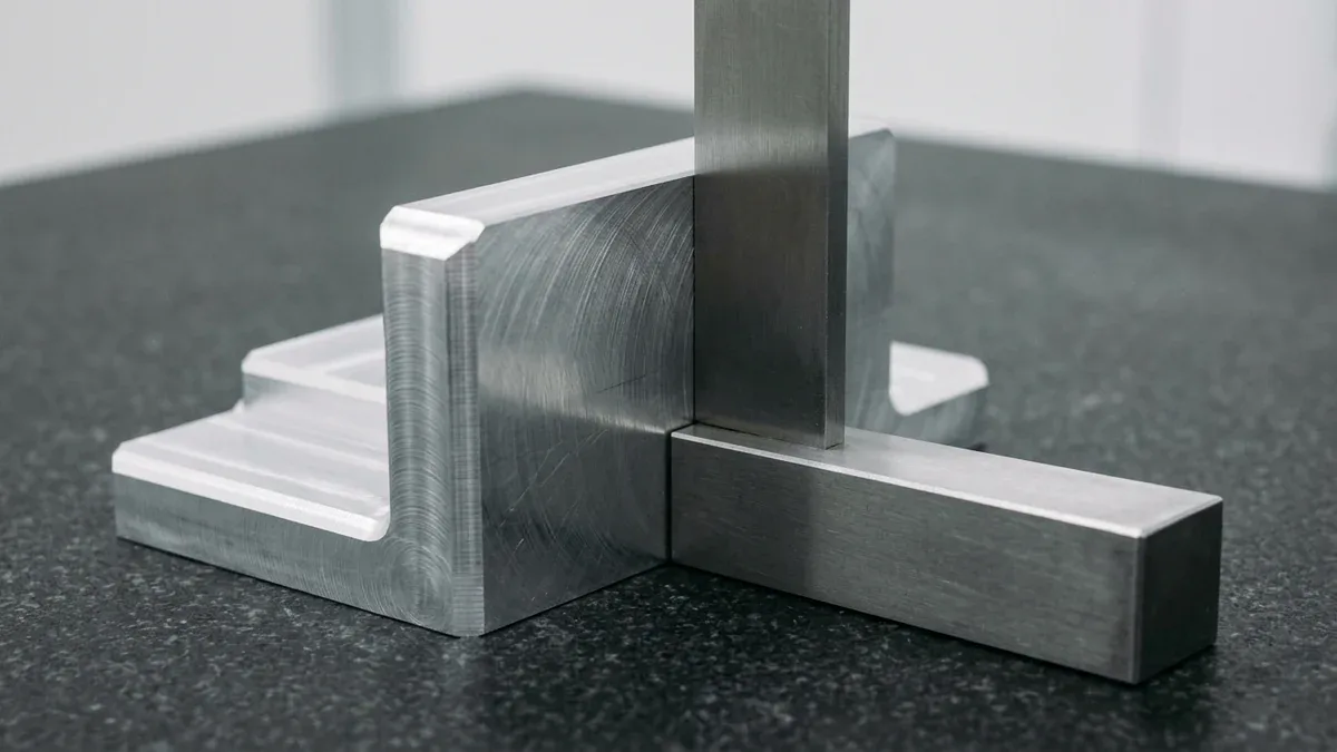
- Critical Feature: 62 mm tall vertical mounting datum wall spanning a length of 110 mm.
- Drawing Requirement: Perpendicularity to primary bottom datum A ≤ 0.015 mm; surface roughness Ra ≤ 0.6 μm; zero visible chatter marks.
The Manufacturing Challenge
The client’s initial prototype supplier attempted to side-mill the 62 mm vertical face in a single finish pass using a standard Ø 12 mm 4-flute carbide end mill in an ER32 collet with an overhang of L = 75 mm (L/D = 6.25:1). The resulting wall displayed an unacceptable 0.058 mm taper from top to bottom due to cutter deflection, completely violating the perpendicularity tolerance.
The AS Prototypes Solution
- Tooling Upgrade: We transitioned to a heavy-core Ø 16 mm 5-flute solid carbide finisher with unequal flute spacing (36°/39°), mounted inside a balanced Haimer thermal shrink-fit toolholder to maximize clamping rigidity and minimize runout.
- CAM Strategy Optimization:
- Roughing: High-efficiency dynamic milling leaving 0.20 mm finishing stock uniformly across the height.
- Semi-Finishing: A climb milling pass at Vc = 320 m/min, ae = 0.15 mm, leaving 0.05 mm final stock.
- Finish Pass with RCTF Compensation: Programmed with ae = 0.05 mm, utilizing compensated feed per tooth fz,comp = 0.08 mm/tooth to ensure clean shear.
- Secondary Spring Pass: Toolpath repeated at zero stock offset to remove residual deflection taper.
Inspection Results: Multi-point coordinate verification on our programmable Zeiss bridge CMM confirmed wall perpendicularity of 0.008 mm (well within the 0.015 mm GD&T budget), and surface roughness measured Ra = 0.42 μm on our contact stylus profilometer, completely eliminating manual polishing operations.
8. Design for Manufacturability (DFM) Rules for Side Milling
Mechanical design engineers can significantly reduce machining complexity and manufacturing costs by incorporating these DFM principles into their CAD models:
- Avoid Excessive Depth-to-Diameter Ratios (L/D): Try to keep vertical wall heights below 3 × the allowable cutter diameter. If a pocket is 60 mm deep, allow at least a Ø 20 mm tool (internal corner radius R ≥ 10 mm) to avoid extreme cutter deflection.
- Add Generous Internal Corner Radii: Internal vertical corners should always specify a radius slightly larger than the cutting tool radius (Rcorner ≥ 1.2 × Rtool). This allows the tool to roll smoothly around the corner rather than stalling in the corner, preventing severe radial chatter marks.
- Provide Relief Grooves at Stepped Shoulders: Where a vertical sidewall meets a horizontal floor, designing a small undercut or relief groove eliminates tool corner wear and ensures mating parts seat flush against the shoulder.
- Distinguish Between Functional & Non-Functional Wall Tolerances: Apply tight perpendicularity (≤ 0.02 mm) only to critical bearing fits, sensor mountings, or optical datums. Non-functional external vertical walls should carry relaxed tolerances (± 0.1 mm) to eliminate the need for costly multi-pass spring passes.
9. Technical Engineering FAQ
When radial depth of cut (ae) is less than 50% of the cutter diameter (D), actual chip thickness is thinner than the programmed feed per tooth. To maintain target chip thickness (h_target) and prevent tool rubbing, the programmed feed per tooth must be increased using fz_comp ≈ h_target / (2 × √(ae / D)).
Program multiple finishing spring passes at final depth, utilize stub-length large-diameter end mills with hydraulic holders, and alternate between climb and conventional passes if necessary to balance deflection.
No. Perpendicularity in GD&T is a total zone width (e.g., 0.015 mm total tolerance band between two parallel planes). It is never specified with a plus-minus (±) sign.
Partner with Our Precision CNC Machining & Engineering Team
Eliminate tool deflection, residual stress distortion, and wall perpendicularity risks before production begins. Upload your 3D CAD files (STEP/IGES) and 2D GD&T drawings for a comprehensive shop-floor DFM review and custom quotation.
Upload 3D CAD for Engineering DFM & RFQ