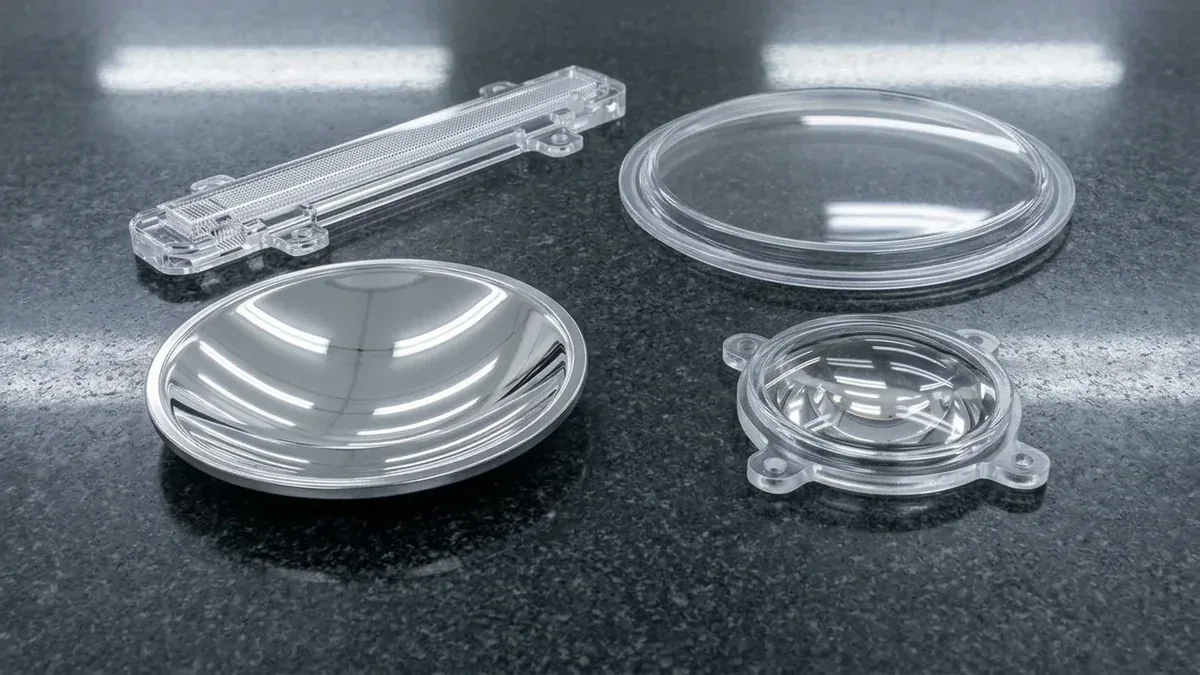
Modern automotive exterior styling, functional aerodynamic sculpting, and active roadway safety are increasingly defined by complex illumination architectures. From slimline matrix LED headlamp projectors and adaptive driving beam (ADB) modules to continuous edge-to-edge rear light bars and illuminated radiator grilles, vehicle lighting assemblies demand absolute harmony between optical physics, structural packaging, and harsh thermal dissipation.
Automotive lighting prototyping serves as the indispensable empirical proving ground bridging computer-aided optical simulation (such as Synopsys LucidShape and Ansys SPEOS) with mass-production multi-cavity injection molds, allowing automotive OEMs and Tier 1 lighting suppliers to validate photometric beam cutoff, lux distribution, and cosmetic surface elegance before capital tool lock.
- 1. Optical Physics Principles: Snell’s Law, TIR & Light Extraction
- 2. Automotive Optical Materials: PMMA, Polycarbonate, PEI & Optical LSR
- 3. Ultra-Precision CNC Machining: Diamond Milling & Freeform Lens Sculpting
- 4. Surface Finishing: Chemical Vapor Polishing & Thermal Stress Relief
- 5. PVD Vacuum Metallization for Parabolic Headlamp Reflectors
- 6. Photometric Darkroom Testing, Goniophotometry & Regulatory Compliance
- 7. Automotive Lighting DFM: 5 Rules to Prevent Optical Hotspots and Haze
- 8. Technical Engineering FAQ
1. Optical Physics Principles: Snell’s Law, TIR & Light Extraction
Automotive light guides (also termed light pipes or optical conduits) operate on the fundamental optical principle of Total Internal Reflection (TIR). When a ray of light traveling through a denser medium (such as acrylic with refractive index n1 ≈ 1.492) strikes an interface with a less dense medium (such as ambient air with n2 ≈ 1.0003), it bends according to Snell’s Law:
n1 · sin(θ1) = n2 · sin(θ2)
When the angle of incidence θ1 exceeds the material’s specific critical angle θc, the angle of refraction θ2 reaches 90°, causing 100% of the luminous energy to reflect internally back into the light guide with zero transmission leakage through the surface:
θc = arcsin(n2 / n1) = arcsin(1.0003 / 1.492) ≈ 42.10°
For optical PMMA, any light ray striking the boundary at an angle greater than 42.10° (measured relative to the surface normal) remains perfectly trapped within the conduit. Conversely, for optical polycarbonate (n1 ≈ 1.586), the critical angle narrows to approximately 39.10°.
However, a continuous light pipe that indefinitely traps light via TIR serves no illumination purpose. To generate a visible daytime running light (DRL) signature, the back surface of the guide must incorporate engineered light extraction features—typically a continuous array of micro-prisms, 45° sawtooth flutes, or laser-etched micro-dots. When traveling light strikes the angled face of an extraction prism, its incident angle drops below θc, breaking TIR and projecting a controlled fan of light through the opposite smooth viewing face.
To maintain uniform perceived luminance along an elongated 800 mm light guide, the extraction prism geometry must compensate for progressive lumen attenuation governed by the Beer-Lambert absorption law (I = I0 · e-αx). Optical engineers dynamically increase prism depth, pitch density, or facet width from the LED in-coupling port toward the distal terminus, transforming an exponential light decay into an impeccably flat luminance output.
2. Automotive Optical Materials: PMMA, Polycarbonate, PEI & Optical LSR
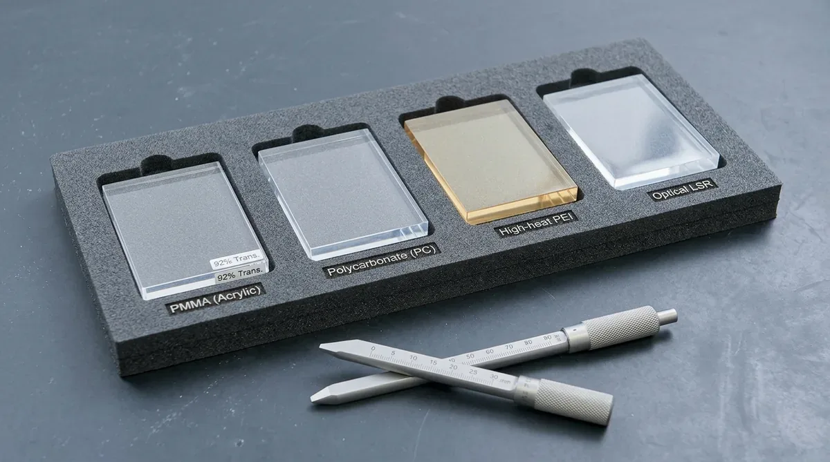
Selecting the appropriate transparent polymer balances light transmission efficiency, mechanical shatter resistance, heat deflection limits, and long-term solar UV durability across the vehicle’s 15-year operational lifecycle.
1. Optical-Grade PMMA (Acrylic)
Polymethyl Methacrylate (PMMA) remains the undisputed gold standard for daytime running lights, interior ambient light guides, and taillamp lens covers. PMMA features an exceptional visible light transmittance of 92.0%, an Abbe dispersion number of 58 (minimizing undesirable color fringing at sharp cutoffs), and inherent chemical immunity to ultraviolet yellowing. With a refractive index of 1.492, PMMA produces clean TIR reflection with minimal internal scattering haze (< 0.5% per ASTM D1003).
2. Optical Polycarbonate (PC)
Outer headlamp lenses must withstand severe external road hazards, including high-speed gravel impacts, curb strikes, and wide thermal extremes (-40°C to +120°C). Optical-grade polycarbonate delivers unmatched Charpy notched impact toughness—many times greater than PMMA—preventing catastrophic lens shattering. However, virgin PC possesses a lower Abbe number (30 to 34) and is susceptible to solar UV degradation and road chemical etching. Exterior PC prototype lenses must receive a thermal-cured or UV-cured polysiloxane hardcoat, elevating surface hardness to ≥ 2H pencil hardness while providing complete UV-A/B shielding.
3. High-Heat Polycarbonate & PEI (Polyetherimide)
In compact matrix LED headlamp projector assemblies, multiple 15-watt LED dies concentrate severe thermal flux within confined envelopes. Inner projector bezels, optical cutoff shields, and primary collimator brackets operate in direct thermal proximity to LED junctions, exceeding standard PC deflection thresholds. High-heat polycarbonate blends (such as Lexan XHT, deflection up to 145°C) and amorphous PEI (Ultem, deflection > 200°C) provide the dimensional stability required to prevent focal drift and eliminate volatile outgassing that could fog inner optical surfaces.
4. Optical Liquid Silicone Rubber (Optical LSR)
For extreme micro-optics and adaptive matrix arrays, two-component Optical LSR provides extraordinary thermal stability up to 150°C without yellowing, paired with high elasticity. Optical LSR allows complex undercut optical geometries and thick-section collimators to be demolded without parting-line flash or sink marks, establishing a vital prototyping pathway for next-generation ADB modules. For a head-to-head comparison of PC and PMMA across lens and sub-assembly roles, read our automotive headlamp prototype materials guide.
| Polymer Grade | Light Transmittance | Refractive Index (nD) | Abbe Number (VD) | Heat Deflection Temp (0.45 MPa) | Primary Lighting Application |
|---|---|---|---|---|---|
| Optical PMMA (Plexiglas) | 92.0% | 1.492 | 58 (Low dispersion) | 95°C – 105°C | DRL light pipes, rear light bars, interior ambient light guides |
| Optical Polycarbonate | 89.0% – 90.0% | 1.586 | 32 (Moderate dispersion) | 125°C – 135°C | Outer headlamp lenses, fog lamp lenses, illuminated grilles |
| High-Heat PC (Lexan XHT) | 87.0% – 89.0% | 1.590 | 30 | 140°C – 150°C | Inner projector bezels, high-output LED cutoff brackets |
| PEI (Ultem 1000) | Translucent Amber | 1.650 | N/A (Structural) | 200°C – 215°C | Direct LED mounting heat shields, projector bracket frames |
| Optical LSR Silicone | 93.0% | 1.410 | 50 | 150°C – 180°C | Matrix LED primary collimators, micro-lens arrays |
3. Ultra-Precision CNC Machining: Diamond Milling & Freeform Lens Sculpting
Producing prototype lighting optics requires manufacturing tolerances and surface roughness profiles that vastly exceed conventional commercial machining standards. In a transmission light pipe, microscopic surface scallops left by an end mill scatter light prematurely, degrading efficiency and creating unsightly bright spots.
At AS Prototypes, our machine shop balances realistic production workflows. High-speed 3-axis and 4-axis machining centers equipped with high-resolution optical rotary tables handle the vast majority of linear light pipes, reflector blocks, and bezel housings. For complex aerodynamic 3D curved outer lenses and multi-faceted freeform projector optics, we add simultaneous 5-axis machining only where the geometry demands continuous cutter engagement without witness lines. For a deeper look at light-guide geometry, see our headlight light guide TIR design guide; for the full lighting service scope, visit our automotive lighting prototyping capabilities.
Single-Point Diamond Milling (SPDM) & Flycutting
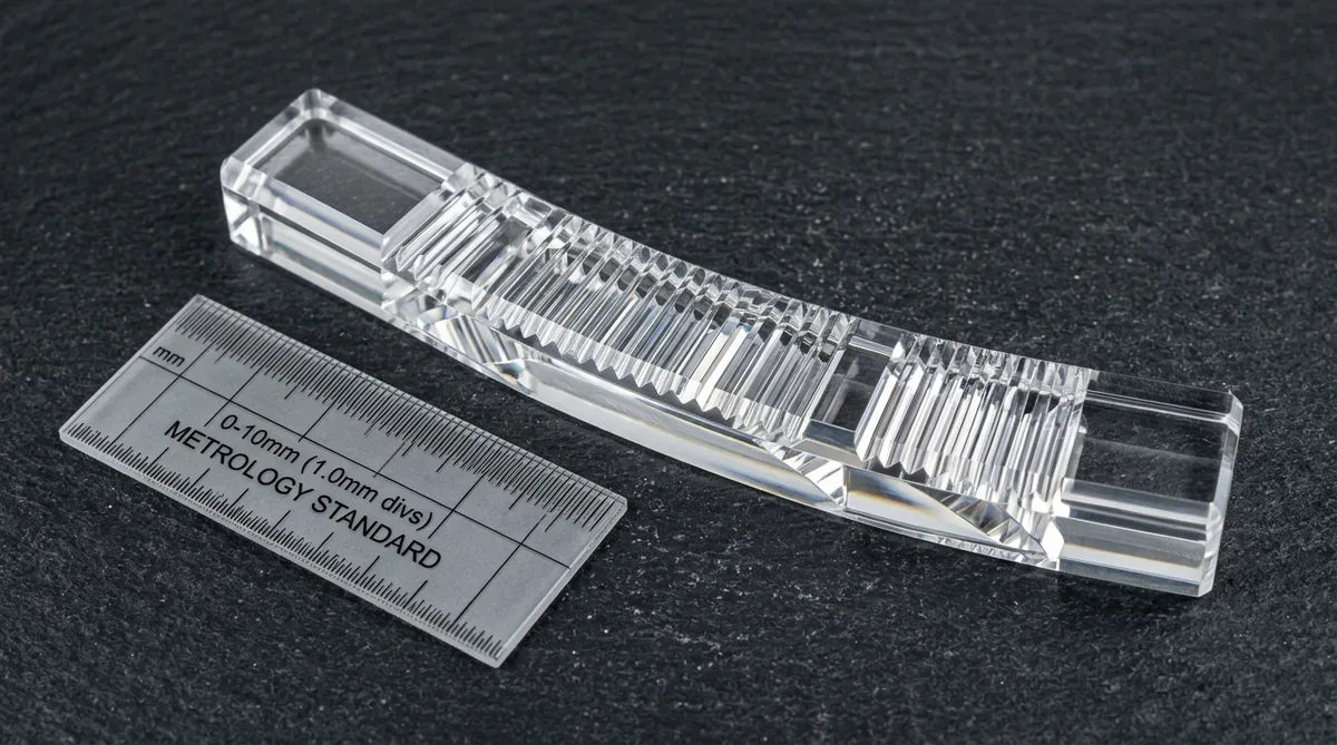
When machining optical PMMA, single-crystal natural or monocrystalline synthetic diamond (MCD) tools deliver true optical mirror finishes directly from the spindle. The extreme sharpness of a monocrystalline diamond cutting edge shears polymer chains cleanly at the shear plane without tearing or micro-cracking the amorphous matrix.
Flycutting optical in-coupling faces with a high-balance diamond cutter head rotating at 15,000 to 24,000 RPM produces optical surface roughness values of Ra = 0.012 to 0.025 μm (SPI A-1 mirror finish equivalent). This mirror clarity enables direct 92% light entry from surface-mounted LEDs without heavy abrasive polishing that could round off precision edges.
Micro-Milling Prism Flutes & Step-Over Kinematics
To carve the intricate micro-groove prism teeth (often with ridge widths as small as 0.15 mm and included angles of 90° ± 0.25°), micro-machining uses custom-ground V-profile single-flute carbide or polycrystalline diamond (PCD) engraving cutters. Feed rates and toolpaths are programmed using micro-trochoidal interpolation and high-frequency look-ahead controllers to eliminate tool dwelling marks at acute vertex corners.
When sculpting complex 3D curved outer lenses (on 5-axis mills for freeform surfaces), fine micro-step-over toolpaths (0.01 to 0.02 mm radial step-over) are executed using spherical ball-end cutters, transforming the curved surface into an easily polishable pre-form without altering focal curvature.
4. Surface Finishing: Chemical Vapor Polishing & Thermal Stress Relief
While acrylic can be diamond-milled directly to optical clarity, polycarbonate reacts differently to mechanical cutting. Due to polycarbonate’s high ductility, milling leaves an opaque, frosted micro-texture that scatters light completely. Transforming a CNC-machined polycarbonate lens into a crystal-clear automotive prototype requires specialized thermal stress-relief annealing and post-machining chemical protocols:
Chemical Vapor Polishing (Solvent Reflow)
In specialized closed-loop vapor polishing chambers, solvent vapors (such as stabilized 1,3-dioxolane or specialized halogenated solvent blends) are heated to vaporization and gently washed over the pre-annealed, frosted polycarbonate workpiece. The volatile vapor condenses uniformly onto the surface, softening and reflowing the outermost 1 to 3 μm resin skin.
Capillary surface tension pulls microscopic peaks into adjacent valleys, completely erasing CNC cutter marks within seconds and restoring glass-like transparency (transmittance > 89%). Unlike mechanical buffing with compound pastes, vapor polishing reflows internal radii, deep flutes, and undercut screw bosses that no polishing wheel or buffing stick could ever access.
Mandatory Thermal Stress-Relief Annealing (60°C–80°C Pre-Polishing Protocol)
CNC milling introduces localized residual tensile stresses into the polycarbonate surface layer. If an unannealed machined PC part is exposed directly to aggressive solvent vapors—or subsequently coated with UV hardcoats and exposed to automotive cleaning agents—it will suffer immediate catastrophic Environmental Stress Cracking (ESC), crazing the lens with a dense network of micro-cracks.
To prevent ESC failure without risking thermal distortion of thin optical walls, all CNC-machined polycarbonate prototypes undergo a mandatory pre-polishing thermal stress-relief annealing cycle inside an industrial convection oven prior to vapor exposure (followed by a gentle 60°C–70°C post-bake to drive off residual solvent):
- Ramp Up: Gradual thermal ramp from ambient room temperature to 60°C–80°C at a controlled rate not exceeding 15°C per hour.
- Soak Phase: Holding at 60°C–80°C for 2 to 4 hours (scaled to wall thickness) to allow polymer chains to relax residual machined stresses prior to solvent vapor exposure without reaching heat deflection distortion.
- Ramp Down: Controlled slow cool-down at ≤ 10°C per hour back to ambient room temperature before opening the chamber and transferring to the vapor polishing unit. This eliminates thermal gradient shocks and guarantees dimensional stability across drawing-specified tolerances.
| Polishing Technique | Applicable Materials | Achievable Roughness (Ra) | Feature Accessibility | Stress Level & Thermal Risk |
|---|---|---|---|---|
| Direct Diamond Flycutting | PMMA (Cast/Extruded) | 0.012 – 0.025 μm | Planar and cylindrical faces only | Near-zero induced stress; no chemical solvent exposure |
| Chemical Vapor Polishing | Polycarbonate (PC) | 0.010 – 0.025 μm | Complete 3D complex contours & deep bores | High solvent stress sensitivity; mandatory 60°C–80°C pre-polishing annealing |
| Manual SPI A-1 Diamond Buffing | PMMA, PC, PS | 0.012 – 0.020 μm | Open exterior curves; rounded edge risk | Moderate frictional heat; risk of rounding sharp optical facets |
| Hydrogen-Oxygen Flame Polishing | PMMA Acrylic only | 0.025 – 0.050 μm | Exterior laser-cut edges only | High thermal stress; strictly prohibited on functional optical prisms |
5. PVD Vacuum Metallization for Parabolic Headlamp Reflectors
While transparent lenses manage light transmission and refraction, parabolic and freeform reflectors gather divergent flux from LED chips and collimate it into high-intensity road projection beams. Achieving authentic photometric test results requires prototype reflectors to duplicate the high-specular reflectivity of production lighting modules.
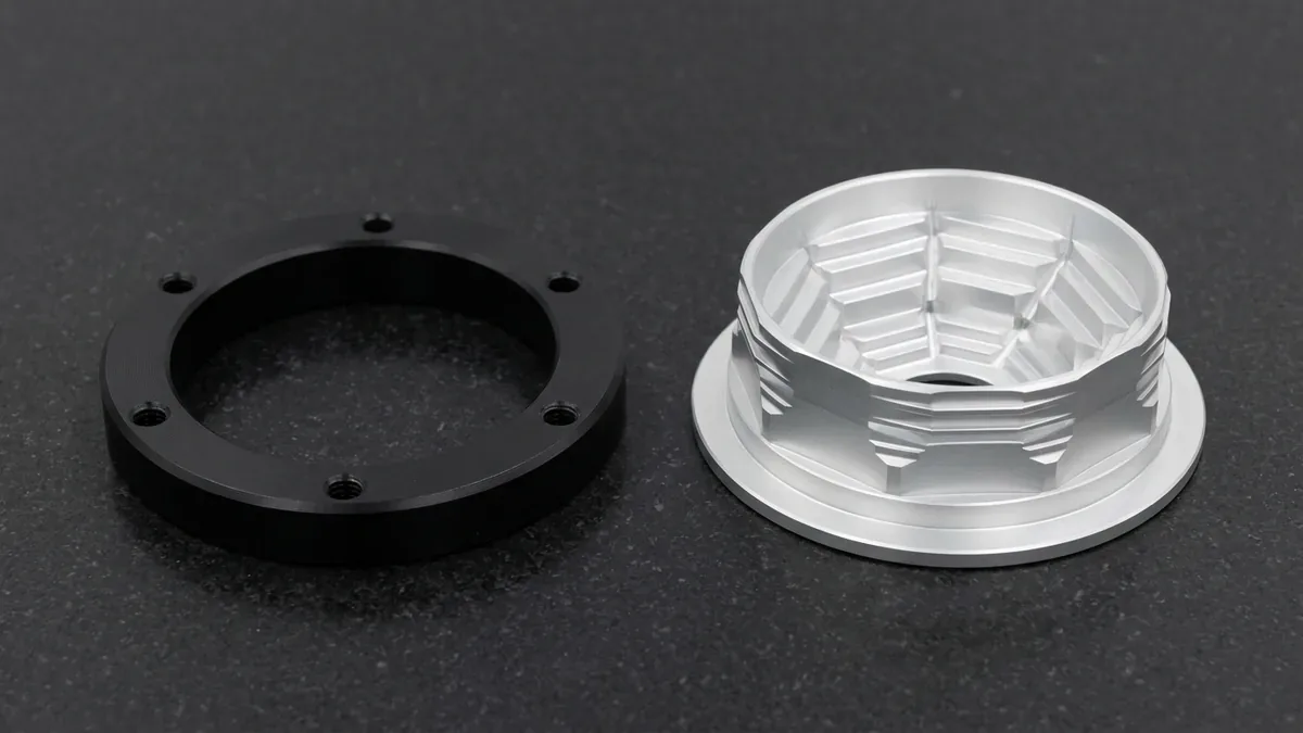
Reflector prototype substrates are precision-machined from dimensionally stable engineering thermoplastics (such as high-heat PC or mineral-filled PBT) or CNC-milled directly from 6061-T6 aluminum billet (see our aluminum reflector prototyping guide for the diamond-turned route). The metallization process follows a disciplined four-stage vacuum deposition regimen:
- Basecoat Smoothing Primer: In polymer substrate reflectors, an ultra-smooth, high-solid thermal-curing basecoat primer is applied via robotic automated spray. The primer levels out micro-machining tool scallops and provides an optically flat, glass-like substrate foundation.
- High-Vacuum Chamber Evacuation: Components are fixtured onto planetary rotation racks inside a high-vacuum chamber pumped down to high vacuum (≤ 5 × 10⁻⁴ mbar / 0.05 Pa) to eliminate atmospheric oxygen and water vapor.
- PVD Aluminum Thermal Evaporation: High-purity aluminum wire (99.99% Al) is vaporized using tungsten filament resistive heating or magnetron sputtering. The vaporized aluminum atoms travel in direct line-of-sight trajectories, condensing onto the rotating reflectors to form a dense, continuous reflective metallic film with a calibrated thickness of 80 to 100 nm (0.08 to 0.10 μm). This nanometer-scale film achieves > 88% specular reflectance across the visible spectrum (400 to 700 nm).
- In-Situ Plasma Polymerized Topcoat (SiOx): Pure aluminum oxidizes and dulls when exposed to ambient moisture. While still under vacuum, hexamethyldisiloxane (HMDSO) monomer gas is introduced into an RF plasma glow discharge. The plasma polymerizes a crystal-clear, dense silica protective barrier (SiOx, ~25 nm thick) directly over the aluminum, so the mirror finish survives humidity and ASTM B117 neutral salt spray exposure without tarnishing.
6. Photometric Darkroom Testing, Goniophotometry & Regulatory Compliance
An automotive lighting prototype is only as valid as its measurable photometric performance. Visual inspection under workshop lighting cannot verify whether a headlamp beam pattern complies with rigorous international transport regulations.
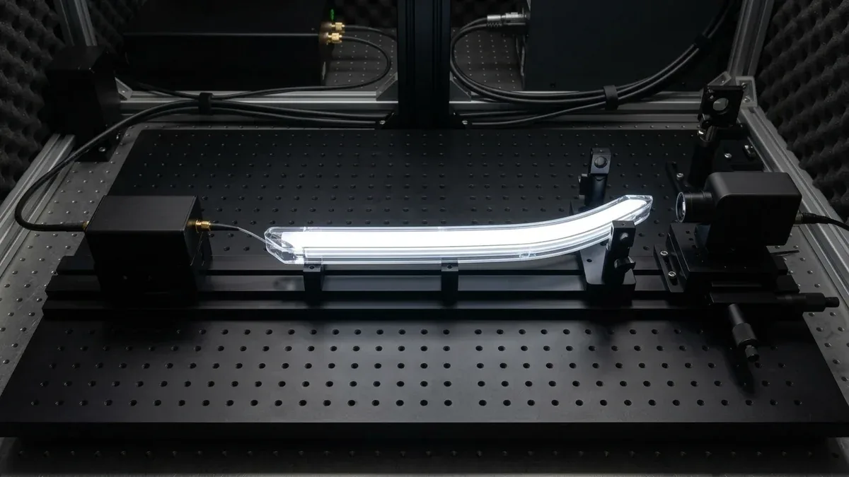
At AS Prototypes, our in-house optical metrology workflow verifies geometric precision using 2.5D Optical Vision Measuring Systems (VMS), Zeiss Bridge CMMs (available upon request), Contact Stylus Profilometers (ISO 4287), and benchtop optical rail LED illumination checks, ensuring prototypes are ready for client or accredited third-party photometric darkroom validation:
- Goniophotometer Type C Coordinate Mapping: The prototype assembly is mounted onto a dual-axis robotic goniophotometer. A calibrated photometer sensor positioned at the standardized photometric test distance (25 m for headlamp regulatory work) maps luminous intensity (candela, cd) across horizontal and vertical angular coordinates, generating high-resolution isocandela contour plots.
- ECE R112/R149 Beam-Pattern & SAE J578 Chromaticity Verification: For passing-beam (low beam) headlamps, photometric software quantifies the sharpness of the asymmetric 15° elbow cutoff line (G-factor gradient ≥ 0.13), confirming adequate downward road illumination without blinding glare for oncoming drivers. A lab-verified prototype supports design validation only; type approval requires production tooling and an accredited test house.
- 2D Imaging Colorimeter & Luminance Camera Testing: For DRL light guides and taillamp bars, a 2D imaging luminance camera captures high-resolution luminance maps (cd/m2), verifying luminance uniformity ratios (ΔLuminance < 15% end-to-end) and confirming chromaticity coordinates (CIE 1931 x, y color space) meet legal automotive white, amber, or red spectrum boundaries.
- Thermal Runaway & Heat Dissipation Mapping: The complete prototype assembly is powered under maximum continuous electrical load inside a sealed environmental chamber while monitored by calibrated FLIR thermal imaging cameras. This verifies heat sink convective airflow and ensures internal air temperatures remain safely below optical polymer heat deflection limits (< 100°C).
7. Automotive Lighting DFM: 5 Rules to Prevent Optical Hotspots and Haze
Eliminating optical defects during prototype CAD modeling saves weeks of tooling iteration. Incorporate these five proven Design for Manufacturability (DFM) rules when engineering automotive lighting components:
- Maintain a Minimum Bend Radius of R ≥ 3·D: In light pipes, acute curvature forces light rays to strike internal walls at angles shallower than the critical angle (θ < θc), causing severe leakage (light bleeding) at the bend and starving the distal end of lumens. Always design light guide centerline bend radii to at least three times the guide diameter or thickness (Rbend ≥ 3 · D). This is a conservative shop rule: the geometric limit for PMMA is about 2.03 · D (1 / (n − 1)), and the extra margin covers off-axis LED rays.
- Incorporate Anti-Hotspot Collimation Distance: Placing high-power LEDs in direct physical contact with the light pipe creates an unsightly intense hotspot at the in-coupling port. Design a dedicated optical in-coupling lens with an integrated 3 to 5 mm air gap or TIR collimating cup to blend and homogenize the LED beam cone before it enters the main guide body.
- Draft Angles for Polished Optical Surfaces (≥ 2° to 3°): When designing optical parts intended for rapid aluminum prototype tooling or vacuum casting, provide at least 2° to 3° of draft on all optical surfaces. Demolding optical PMMA or PC with insufficient draft causes micro-scuffing along the parting walls, instantly clouding the lens with optical haze.
- Uniform Wall Thickness to Eliminate Thermal Sink Marks: Thick polymer walls (> 4.0 mm) develop severe differential cooling rates that produce surface depression sink marks. In optical components, a sink mark as shallow as 0.02 mm functions as an unintended concave lens, distorting beam projection. Maintain uniform wall sections (2.5 to 3.5 mm) and core out thick boss features from non-optical rear zones.
- Design Clamping Tabs Outside the Optical Boundary: Symmetrical optical lenses require rigid mechanical workholding during CNC diamond milling. Incorporate sacrificial peripheral perimeter clamping tabs and datum indexing holes located outside the functional optical aperture. These tabs provide rigid vise fixturing and CMM probing datums, and are parted off in the final deburring stage.
8. Technical Engineering FAQ
Optical PMMA provides superior visible light transmittance (92.0% vs 89.0%), lower chromatic dispersion (Abbe 58 vs 32), and complete natural resistance to solar UV yellowing. Its pristine clarity allows light to travel along lengthy 800 mm light guides via total internal reflection (TIR) with minimal absorption loss compared to polycarbonate.
After precision CNC milling with fine micro-step toolpaths, the polycarbonate lens undergoes mandatory 60°C to 80°C pre-polishing thermal stress-relief annealing for 2 to 4 hours to relax machining stresses and prevent environmental stress cracking (ESC). It is then treated with chemical vapor polishing to briefly reflow the outermost surface layer, followed by an optical UV-resistant polysiloxane hardcoat.
Yes for design validation. By combining precision diamond machining, vacuum metallized PVD reflectors, and production-grade optical polymers, our prototypes closely match the luminous efficiency, beam cutoff sharpness, and colorimetry of serial lamps, so goniophotometric checks against ECE and SAE targets can run before production tooling is cut. Formal type approval, however, requires production-intent parts and an accredited test house.
Individual optical components (such as CNC-milled PMMA light guides or diamond-machined lenses) with vapor polishing or other finishing are typically delivered in 7 to 12 business days. Complete multi-component lighting assemblies—including machined outer lenses, vapor polishing, PVD metallized reflector bowls, and functional LED wiring harnesses—take 15 to 30 business days. These are Ex-Factory Production & Inspection Turnaround times, separate from 3 to 5 days of DHL/FedEx/UPS air transit.
Uneven brightness typically results from improper in-coupling distance from the LED, severe tight bend radii ( R < 3 D ) that prematurely break total internal reflection (TIR), or non-linear light extraction prism density. Optical simulation and precision diamond micro-milling ensure extraction flutes gradually increase in depth and density along the guide to maintain uniform luminance.
Accelerate Your Automotive Lighting & Optical Prototyping
Eliminate optical hotspots, TIR leakage, and environmental stress cracking before production tooling begins. Upload your 3D CAD models (STEP/IGES) and optical drawings for a comprehensive DFM review covering diamond milling, vapor polishing, and PVD vacuum metallization.
Upload 3D CAD for Optical & Lighting DFM Review