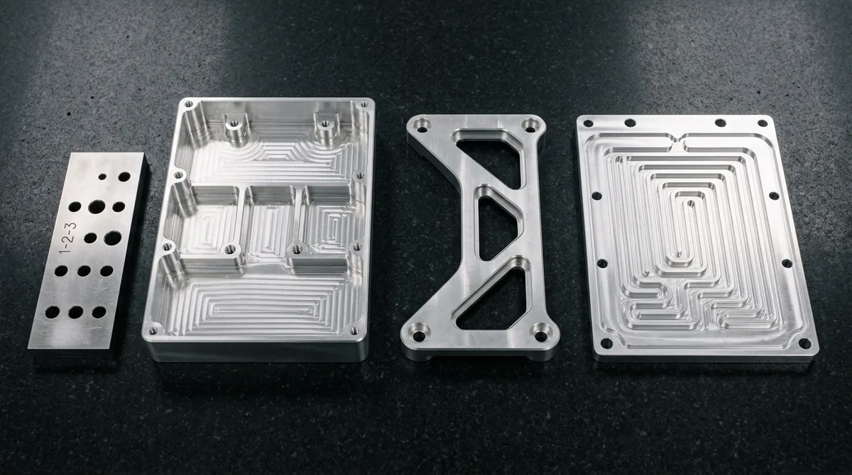
Milled aluminum components serve as the foundational backbone of modern mechanical engineering across aerospace structures, robotics motion systems, automotive thermal assemblies, and precision electronics enclosures. Delivering an optimal balance of high strength-to-weight ratio, superior thermal conductivity (130 to 167 W/m·K), and rapid subtractive machinability, aluminum alloys allow engineering teams to validate functional prototypes and scale into low-volume production seamlessly.
In our specialized precision CNC milling services machine shop, deploying optimized cutting dynamics, mirror-polished carbide tooling, and bilateral stress-relief strategies ensures that every milled aluminum component achieves exacting geometric tolerances down to ±0.010 mm (±0.0004″) and pristine surface finishes. Explore our companion analysis on the advantages of aluminum prototypes to evaluate material trade-offs across functional testing cycles.
- Alloy Spectrum: General structural components leverage 6061-T6 for balanced strength and cosmetic anodizing; high-load aerospace hardware demands 7075-T651 for 503 MPa (73.0 ksi) yield strength.
- Machining Tolerances: Standard shop-floor milling adheres to ISO 2768-mK (±0.127 mm / ±0.005″); precision CNC milling holds drawing tolerances of ±0.010 mm / ±0.0004″; wire EDM and surface grinding reach ±0.005 mm (±0.0002″).
- Surface Refinement: Standard as-milled finish achieves Ra 0.8 µm (32 µin); fine #120 glass bead blasting produces a satin matte texture; MIL-A-8625 Type II and Type III hard anodizing deliver durable wear and corrosion barriers.
- Production Turnaround: Functional milled prototypes ship in 4 ~ 8 business days; anodized assemblies deliver in 7 ~ 12 business days; low-volume production (10 ~ 1,000+ parts) completes in 7 ~ 30 business days (ex-factory).
1. Metallurgy and Alloy Selection for Milled Aluminum
Aluminum alloy selection dictates the fundamental balance between yield strength, thermal dissipation, machinability index, and cosmetic anodizing response. Precipitation-hardened wrought alloys (such as the 6000 and 7000 series) dominate structural milling, while cast tooling plates provide exceptional dimensional stability for metrology fixtures.
Selecting the correct temper and chemical composition prevents premature component failure under dynamic mechanical stress while ensuring economical chip formation on the machine floor:
- Aluminum 6061-T6: The global standard for general-purpose precision milling. Alloyed primarily with magnesium and silicon, 6061-T6 exhibits a balanced yield strength of 276 MPa (40.0 ksi), high fatigue resistance, excellent corrosion protection, and uniform anodic response. It serves as the primary material for robotic chassis, drone arms, heatsinks, and industrial brackets.
- Aluminum 7075-T651: An ultra-high-strength aerospace-grade zinc alloy. Yield strength exceeds 503 MPa (73.0 ksi) with ultimate tensile strength reaching 572 MPa (83.0 ksi)—comparable to structural carbon steel at one-third the mass. Deployed in aircraft bulkheads, suspension uprights, and high-stress motorsport linkages.
- Aluminum 2024-T3: Copper-rich aerospace alloy engineered for maximum cyclic fracture toughness and fatigue resistance under cyclic tension. Ideal for aviation fuselage shear webs, tension fittings, and structural wing ribs.
- Aluminum 5083-H111: Non-heat-treatable magnesium alloy offering unmatched resistance to marine saltwater corrosion, harsh chemical exposure, and cryogenic embrittlement. Standard choice for marine deck fittings, subsea housings, and pressure manifolds.
- MIC-6 Cast Tooling Plate: Continuously cast aluminum-magnesium plate fully granularized to relieve internal stresses. Offers a yield strength of 105 MPa (15.2 ksi) with near-zero residual stress, holding surface flatness within 0.13 mm (0.005″) across large spans without machining distortion.
| Alloy Grade & Temper | Yield Strength (MPa / ksi) | Tensile Strength (MPa / ksi) | Thermal Cond. (W/m·K) | Machinability Index (%) | Relative Cost Ratio | Recommended Application / When to Choose |
|---|---|---|---|---|---|---|
| 6061-T6 | 276 MPa (40.0 ksi) | 310 MPa (45.0 ksi) | 167 | 85% (Excellent) | 1.0x (Baseline) | Best for general housings, brackets, heatsinks, and uniform cosmetic anodizing. |
| 7075-T651 | 503 MPa (73.0 ksi) | 572 MPa (83.0 ksi) | 130 | 75% (Crisp chip) | 1.6x | Best for high-load aerospace bulkheads, motorsport uprights, and high-stress linkages. |
| 2024-T3 | 324 MPa (47.0 ksi) | 469 MPa (68.0 ksi) | 121 | 80% (Very Good) | 1.4x | Best for cyclic fatigue tension components, aircraft ribs, and structural shear webs. |
| 5083-H111 | 145 MPa (21.0 ksi) | 318 MPa (46.1 ksi) | 121 | 65% (Ductile) | 1.3x | Best for marine saltwater service, cryogenic fluid handling, and welded subsea valves. |
| MIC-6 Cast Tooling | 105 MPa (15.2 ksi) | 165 MPa (23.9 ksi) | 142 | 90% (Zero stress) | 1.5x | Best for large CMM inspection platens, vacuum fixtures, and semiconductor baseplates. |
While 7075-T651 offers extraordinary mechanical strength, design engineers must avoid specifying it for assemblies requiring fusion welding. Zinc alloying elements vaporize during TIG/MIG welding, inducing severe hot cracking and micro-porosity along the heat-affected zone (HAZ); mechanical fastening or structural adhesives must be used instead. Furthermore, 7075-T6 is significantly more susceptible to stress corrosion cracking (SCC) than 5083 or 6061 in marine salt-spray environments and must never be exposed bare without a sealed Type III hardcoat barrier.
2. High-Speed 3-Axis & 4-Axis CNC Milling Dynamics & Tooling
High-speed CNC milling of aluminum requires balanced cutting physics, high spindle velocities (12,000 to 20,000 RPM), and aggressive chip evacuation geometries to prevent thermal accumulation in the workpiece. Because aluminum is ductile with a relatively low melting point (~660°C), improper chip loading leads instantaneously to built-up edge (BUE), where overheated aluminum micro-welds to the tool flutes and causes catastrophic cutter breakage.
In our machine shop practice, high-speed 3-axis and 4-axis vertical machining centers (VMCs) constitute between 75% and 85%+ of overall manufacturing capacity. Prismatic enclosures, mounting brackets, liquid cold plates, and interface panels are machined with maximum economic efficiency using high-speed 3-axis setups equipped with precision steel vises or aluminum soft jaws, while 4-axis rotary indexers handle compound multi-angle bores. Simultaneous 5-axis milling is strategically reserved for intricate spatial contours, impellers, and deep 5-sided manifold geometries.
| Operation Type | Tooling Configuration | Cutting Speed (SFM / m/min) | Chip Load (IPT / mm/tooth) | Coolant & Evacuation Strategy |
|---|---|---|---|---|
| High-Efficiency Roughing (HEM) | 3-Flute Carbide End Mill (ZrN Coated) | 2,000 ~ 3,500 SFM (600 ~ 1,060 m/min) | 0.004″ ~ 0.008″ (0.10 ~ 0.20 mm) | High-pressure flood coolant (30 ~ 70 bar) or vortex cold air blast |
| Face Milling & Datum Surfacing | Indexable Shell Mill (Polished PCD / Carbide) | 2,500 ~ 4,500 SFM (760 ~ 1,370 m/min) | 0.008″ ~ 0.016″ (0.20 ~ 0.40 mm) | Through-spindle air blast with wiper insert for Ra ≤ 0.4 µm finish |
| Deep Pocket Cavity Clearing | Relieved-Neck 3-Flute End Mill (45° Helix) | 1,800 ~ 2,800 SFM (550 ~ 850 m/min) | 0.003″ ~ 0.006″ (0.08 ~ 0.15 mm) | Directed directional air blast to lift curled chips out of deep cavities |
| Wall & Floor Finishing Passes | Mirror-Polished Solid Carbide (DLC Coated) | 2,800 ~ 4,000 SFM (850 ~ 1,220 m/min) | 0.002″ ~ 0.004″ (0.05 ~ 0.10 mm) | Synthetic micro-lubrication mist (MQL) for uniform Ra 0.8 µm texture |
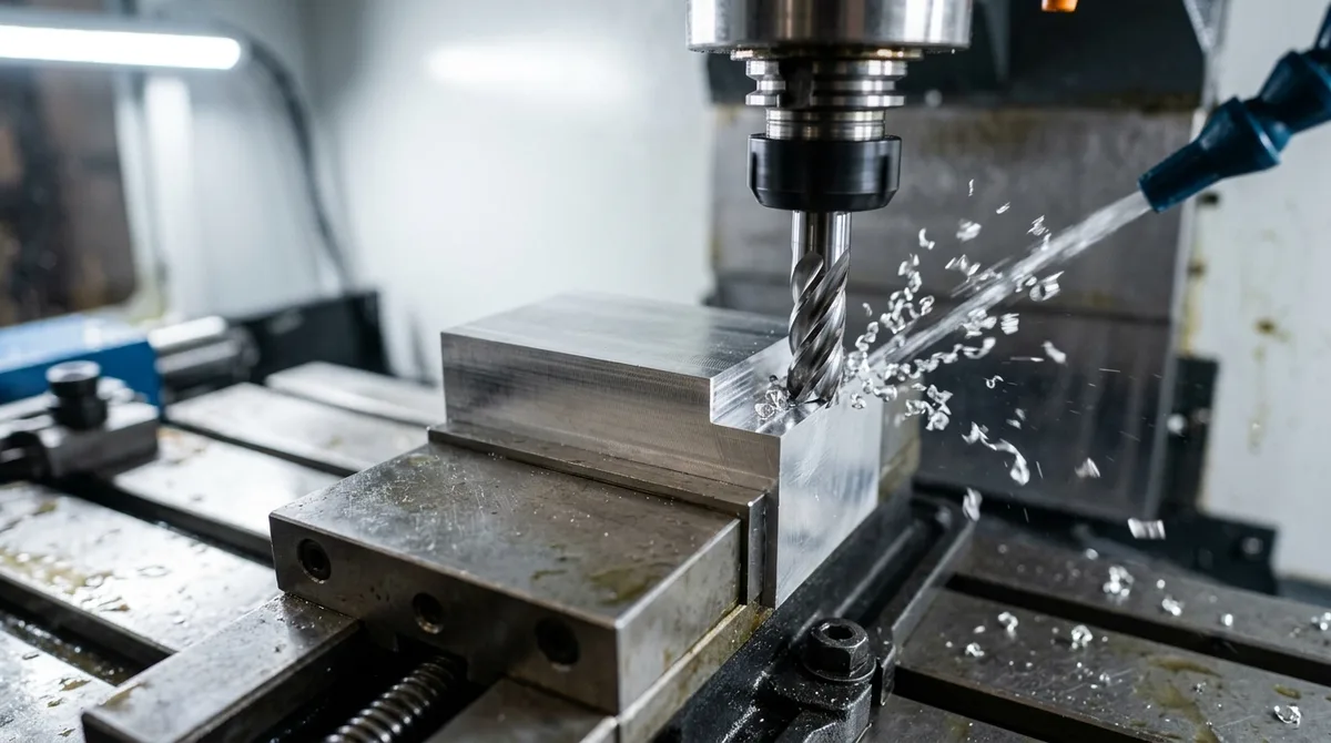
To eliminate chip sticking during aggressive high-speed roughing, end mills feature 3-flute cylindrical geometries with 37° to 45° high helix angles and mirror-polished flute faces. Zirconium Nitride (ZrN) and Diamond-Like Carbon (DLC) physical vapor deposition coatings provide a friction coefficient below 0.1 against raw aluminum, completely preventing chip welding. As demonstrated in the CNC vertical milling setup below, directing a high-velocity vortex air stream across the tool-workpiece interface instantly clears curled aluminum chips away from the cutting shoulder, maintaining clean shear physics across every spindle pass.
3. Why Does Thin-Wall Milled Aluminum Warp During CNC Machining?
Thin-wall milled aluminum components warp primarily due to the asymmetric release of internal residual stresses introduced during billet rolling and rapid quenching, compounded by clamping deformation and high localized thermal expansion. When material is hogged out from one side of a wrought billet, the delicate equilibrium of residual tensile and compressive stresses is severed, forcing the remaining thin walls and floor to bow elastically.
Thermal sensitivity further amplifies distortion on the shop floor. Aluminum possesses a high linear thermal expansion coefficient of approximately α ≈ 23 × 10⁻⁶ / K. Consider an engineering calculation for a 150 mm long 6061-T6 aluminum optical chassis: under an uncontrolled shop-floor temperature rise of ΔT = 5°C, thermal expansion drift produces ΔL = α · L · ΔT = 23 × 10⁻⁶ × 150 × 5 = 0.0173 mm (0.00068″). This thermal expansion instantly exceeds a drawing tolerance of ±0.010 mm (±0.0004″).
To conquer thin-wall distortion and hold true position within ±0.010 mm, our CNC milling engineering team enforces a strict 3-step shop-floor stress mitigation protocol:
- Step 1: Bilateral Equal Stock Roughing – Machinists remove equal stock thicknesses from opposing faces in alternating setups rather than hogging out deep cavities in a single pass. Balancing skin tension across the billet neutralizes bowing forces.
- Step 2: Unclamping & Thermal Relaxation Cycle – Following heavy roughing, parts are completely unclamped from the machining vise and allowed to rest at a controlled 20°C ambient room temperature for elastic relaxation. Parts are then re-clamped with calibrated low torque for semi-finishing.
- Step 3: Vacuum Fixturing & Dynamic Step-Down Toolpaths – For large thin floors (thickness < 2.0 mm), dedicated vacuum chucks distribute holding force across the entire planar surface, eliminating localized vise-jaw pinching. Toolpaths employ synchronized step-down levels where interior cavities and exterior perimeters descend concurrently to preserve structural wall rigidity.
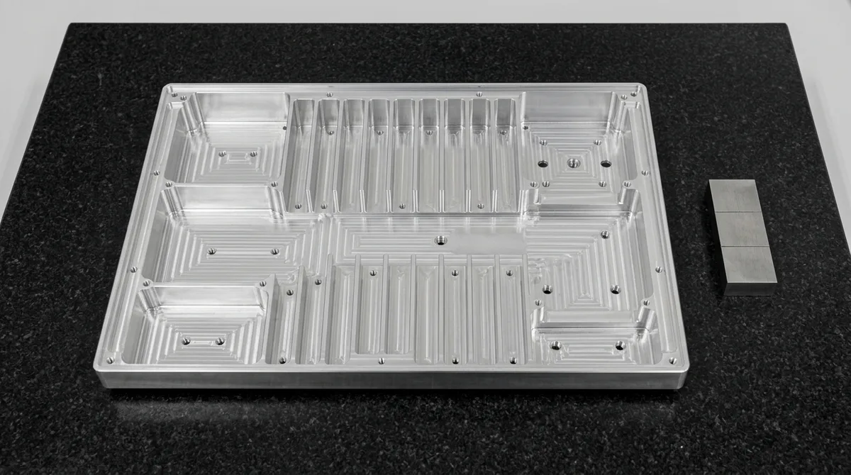
As illustrated in the precision thin-wall electronics chassis below, integrating uniform 1.0 mm (0.040″) vertical ribs with bilateral step-down floor levels stabilizes the enclosure against post-machining twisting, enabling flawless alignment of mating optical connectors.
4. Surface Finishing, Anodizing & Thread Tolerance DFM
Surface finishing for milled aluminum transforms raw as-machined surfaces into robust, corrosion-resistant, and aesthetically refined enclosures. However, post-machining finishes alter critical part dimensions, requiring precise Design for Manufacturability (DFM) tolerance offsets prior to cutting metal.
The standard as-milled finish achieves a surface roughness of Ra 0.8 µm (32 µin) on precision passes, characterized by uniform semi-circular flycutting toolpaths. When cosmetic uniformity is required, fine #120 glass bead blasting under 3.5 to 4.0 bar pneumatic pressure obliterates directional cutter paths, creating an elegant non-directional matte satin texture.
Anodic oxidation converts base aluminum into an aluminum oxide ceramic barrier. Crucially, the oxide layer penetrates 50% into the substrate and builds 50% outward from the original surface. Under MIL-A-8625 Type II sulfuric acid anodizing (coating thickness 10 to 20 µm), outward growth adds 5 to 10 µm (0.0002″ to 0.0004″) per surface, increasing outer diameters by 10 to 20 µm and reducing internal bore and thread pitch diameters by equivalent amounts.
Under MIL-A-8625 Type III hardcoat anodizing (coating thickness 25 to 50 µm), outward growth builds 12.5 to 25 µm per surface. Internal threads (such as M3, M4, or 4-40 UNC) must be cut with oversize 6G/7H taps prior to coating to avoid post-anodizing fastener binding.
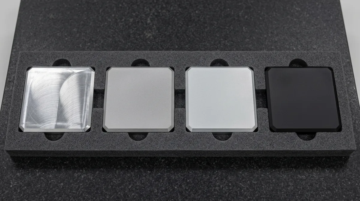
The standardized test coupon set below demonstrates the visual and tactile contrast across four primary aluminum finishing states: raw as-milled with delicate toolpath swirls, bead-blasted satin matte, Type II clear anodized protective layer, and Type III deep black hardcoat anodized ceramic shield.
5. Precision Metrology, GD&T and Zeiss CMM Verification
Precision metrology validates that geometric dimensioning and tolerancing (GD&T) specifications on engineering drawings are faithfully translated into physical aluminum hardware. Holding tight true positions within ±0.010 mm (±0.0004″) and flatness within 0.008 mm (0.0003″) requires coordinated in-situ machine probing coupled with definitive offline coordinate measuring machine (CMM) verification.
Our quality control workflow operates inside a climate-controlled inspection laboratory stabilized at 20°C ± 0.5°C to eliminate thermal expansion drift. Machined components are placed in a free, unclamped state on vibration-isolated black granite metrology plates, completely eliminating external fixturing stresses during measurement.
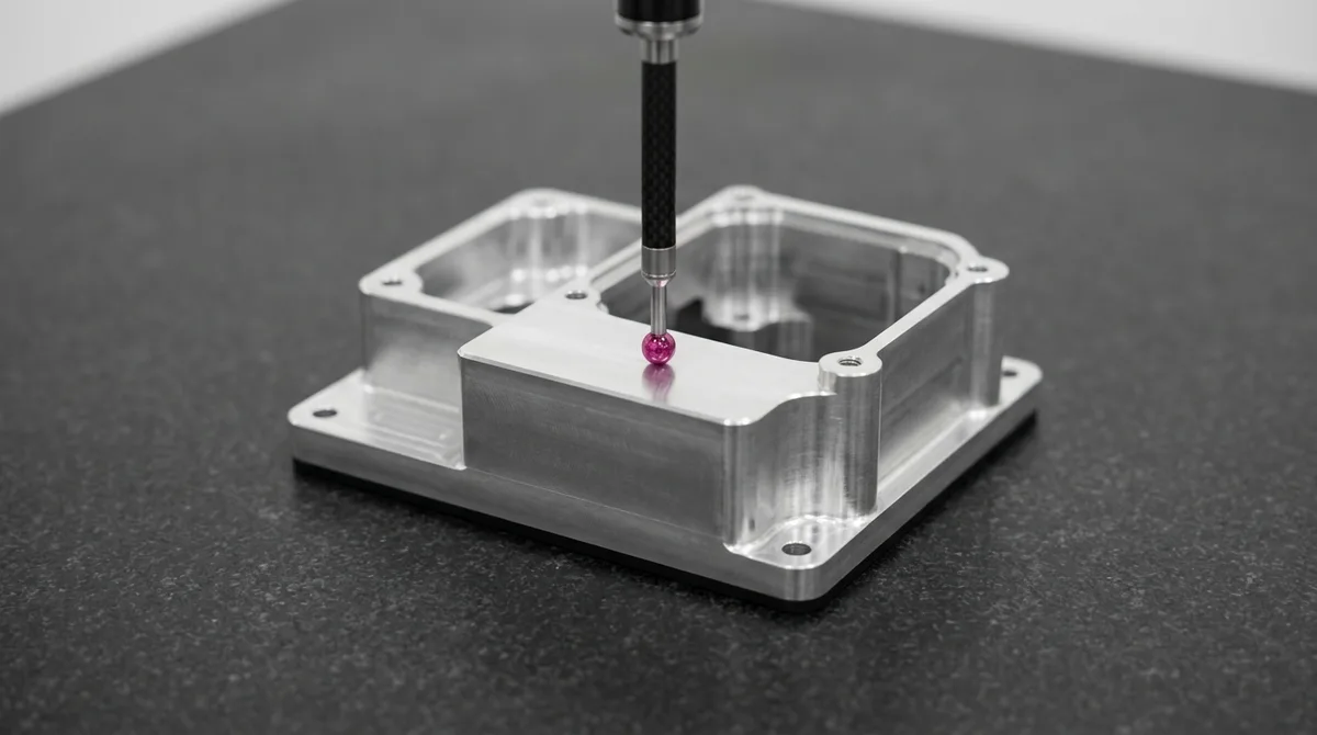
As captured in the metrology inspection setup below, the calibrated ruby ball tip of a Zeiss CMM vertical measuring probe touches the flat top Datum Plane A in open air. The slender carbon-fiber probe stem maintains 360-degree clearance away from all sidewalls and flanges, eliminating probe shank collisions and delivering sub-micron measurement repeatability.
6. Shop-Floor Troubleshooting: Root Causes & Corrective Actions
Based on our Shenzhen manufacturing facility records across hundreds of custom CNC milling runs, resolving machining anomalies quickly separates elite machine shops from conventional suppliers. The troubleshooting matrix below provides actionable shop-floor remedies for common milled aluminum challenges:
| Observed Symptom | Underlying Root Cause | Shop-Floor Corrective Action |
|---|---|---|
| Wall Chatter & Harmonic Ripples | Excessive tool overhang (L/D > 4:1) or natural frequency resonance with thin workpiece wall. | Switch to variable-helix 3-flute end mill; reduce radial engagement (ae ≤ 10% D); increase feed per tooth to dampen vibration. |
| Built-Up Edge (BUE) & Surface Smearing | Insufficient surface footage (SFM < 1,500) causing chips to friction-weld to carbide flutes. | Elevate cutting speed (Vc > 600 m/min); deploy mirror-polished ZrN or DLC coated cutters; optimize vortex air blast. |
| Post-Anodizing Thread Binding | Failure to compensate for 50% outward anodic oxide layer growth in tapped internal holes. | Pre-machine internal threads with 6G or 7H oversize taps or thread mills before sending to anodizing bath. |
| Box Enclosure Bowing / Warping | Asymmetric unilateral stock hogging releasing rolling skin stresses unevenly across billet. | Equalize roughing passes bilaterally; execute intermediate unclamping stress relaxation before taking final skim passes. |
7. Engineering Decision Tree: Selecting the Ideal Milled Aluminum Setup
To streamline material specification and production planning, utilize our shop-floor engineering decision rules across four distinct operational priorities:
- Budget & Rapid Turnaround Priority: Specify 6061-T6 aluminum machined on high-speed 3-axis VMCs with standard ISO 2768-mK tolerances (±0.127 mm). Pair with as-machined (Ra 0.8 µm) or Type II clear anodizing for the fastest 4 ~ 8 business day turnaround.
- High Mechanical Load & Aerospace Priority: Select 7075-T651 aluminum. Implement bilateral stress-relief milling routines and verify primary datums via CMM inspection. Finish with MIL-A-8625 Type III hardcoat anodizing for maximum surface microhardness (>450 HV0.05).
- Extreme Marine & Cryogenic Priority: Choose 5083-H111 aluminum for superior resistance to saltwater pitting and cryogenic embrittlement. Avoid sharp internal radii (maintain R ≥ 1.5 mm) to facilitate smooth chip evacuation during roughing.
- Zero-Stress Metrology & Vacuum Fixtures: Specify MIC-6 cast tooling plate. Utilize high-speed diamond flycutting to achieve surface flatness within 0.010 mm across broad spans without clamping distortion.
Frequently Asked Questions
Standard shop-floor milling tolerances for aluminum follow ISO 2768-mK at ±0.127 mm (±0.005″). Precision CNC milling in climate-controlled environments achieves drawing tolerances of ±0.010 mm (±0.0004″), while specialized wire EDM and precision grinding hold ultra-tight tolerances down to ±0.005 mm (±0.0002″).
Thin-walled aluminum warps when material removal releases asymmetric internal residual stresses from raw rolled billets, combined with localized machining heat. Machinists prevent warping by roughing equal stock from opposing faces bilaterally, performing an intermediate unclamping stress-relief cycle, and utilizing vacuum chuck fixturing.
Anodizing builds an oxide layer that penetrates 50% into the aluminum and grows 50% outward. Type II anodizing adds 5 to 10 µm (0.0002″ to 0.0004″) outward per surface, while Type III hardcoat adds 12.5 to 25 µm. Internal threads must be pre-machined with oversize 6G/7H taps to prevent fastener binding.
Aluminum 6061-T6 is an economical, general-purpose alloy offering 276 MPa yield strength, excellent weldability, and superior cosmetic anodizing. Aluminum 7075-T6 is an aerospace-grade alloy with 503 MPa yield strength for high-load applications, but it cannot be fusion welded and exhibits lower corrosion resistance in marine environments.
Precision Milled Aluminum Parts Delivered on Demand
From rapid functional prototypes to production runs with MIL-A-8625 Type II/III anodizing, our in-house machine shop delivers tight tolerances down to ±0.010 mm (±0.0004″) and CMM verification. Upload your 3D CAD files (STEP/IGES) for a thorough engineering DFM review and custom quotation.