BLUF: Bottom Line Up Front
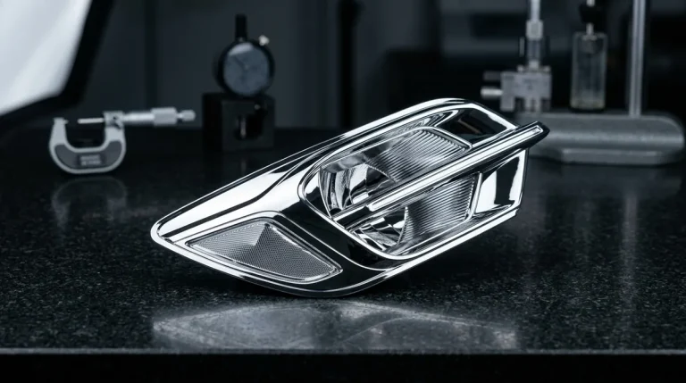
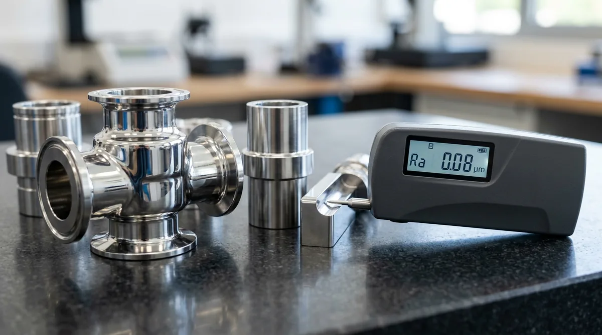
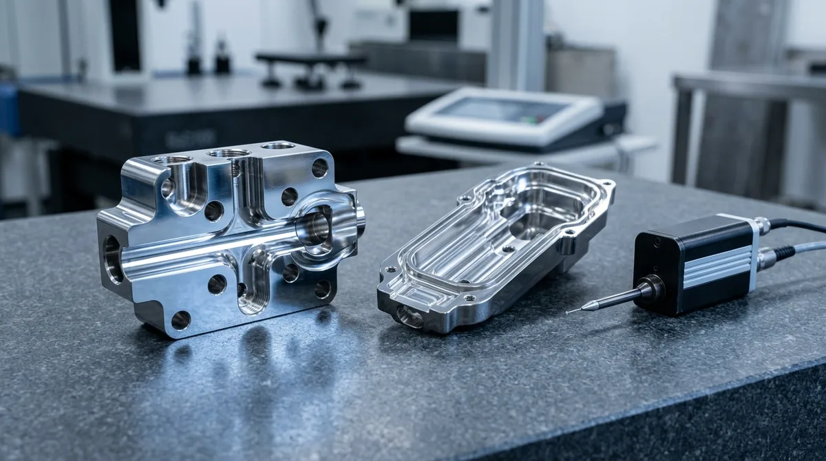
Metal polishing techniques are precision surface engineering operations that methodically reduce surface roughness from as-machined states (Ra 1.6 to 3.2 μm) down to optical mirror finishes (Ra ≤ 0.025 μm / SPI A-1). Selecting the correct polishing modality depends on part geometry, material hardness, and functionality: Mechanical Progressive Lapping & Buffing (ideal for flat mold cavities and optical aluminum reflectors), Electropolishing (ASTM B912) (the gold standard for 304/316L stainless steel, removing 10 to 25 μm of microscopic peaks without cold-working stress), Chemical Polishing (complex aluminum extrusions and brass), Vibratory Mass Finishing (high-volume isotropic deburring), and Centrifugal Magnetic Pin Finishing (intricate micro-fluidic channels).
Core Engineering Impact: Optical surface polishing eliminates micro-notches to elevate component fatigue endurance limits (σe) by 20% to 35%, lowers dynamic fluid boundary-layer turbulence, and ensures hermetic sealing integrity (Rz ≤ 0.40 μm) on high-pressure vacuum and hydraulic interfaces.
In high-precision manufacturing, metal polishing is far more than a cosmetic final operation. Surface micro-topography directly governs tribological friction, hydrodynamic boundary-layer drag, fatigue crack initiation, and microbiological cleanability. Whether manufacturing aerospace aluminum parabolic reflectors, semiconductor ultra-pure gas delivery valves, or medical surgical implants, surface peak-to-valley roughness must be systematically controlled through validated physical and chemical finishing sequences.
When parts exit multi-axis CNC milling, wire electrical discharge machining (EDM), or casting cells, their surfaces exhibit microscopic periodic tool marks, cusps, and recast layers. Polishing transforms these irregular micro-peaks into smooth, continuous bearing plateaus. However, improper polishing pressures or incorrect abrasive progressions introduce severe surface flaws, including “orange peel” grain yielding, abrasive grit pull-out, and localized dimensional distortion.
At AS Prototypes, our surface finishing division integrates precision CNC machining with manual SPI mold benching, automated vibratory mass finishing, chemical brightening, and industrial electropolishing baths. In this comprehensive technical guide, we analyze surface topography mathematics, derive Faraday’s law of electropolishing dissolution, compare industrial polishing modalities, present step-by-step diamond polishing protocols, and outline engineering rules to achieve pristine, defect-free metal finishes.
1. Surface Roughness Topography: Mathematical Metrics & SPI Standards
Engineering drawings specify surface micro-geometry using standardized roughness parameters defined under ISO 4287 and ASME B46.1. Contact stylus profilometers and non-contact white light interferometers quantify these microscopic profiles.
1.1 Roughness Average (Ra) vs Mean Peak-to-Valley Height (Rz)
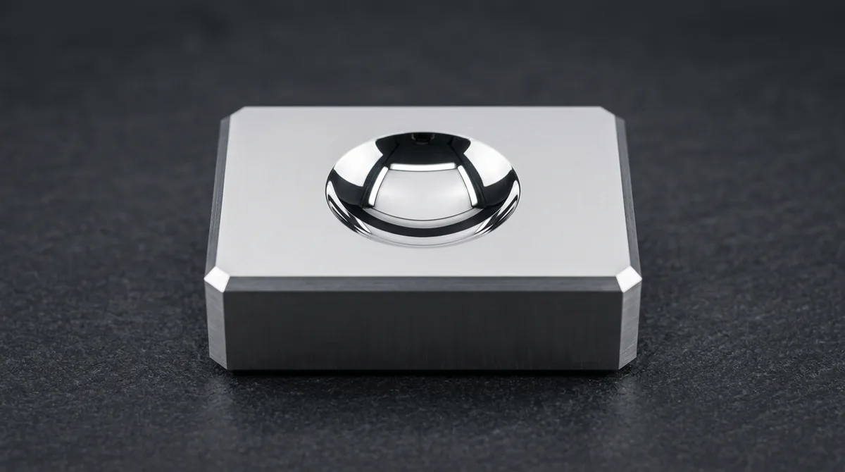
The most widely referenced metric is Roughness Average (Ra), the arithmetical mean deviation of the roughness profile from the mean centerline across evaluation length L:
While Ra provides a reliable baseline for general machining quality, it averages out individual profile spikes and scratches. In dynamic sealing interfaces (such as hydraulic piston seals or ultra-high-vacuum knife edges), a single deep micro-groove will cause catastrophic fluid leakage, even if the overall surface exhibits an acceptable Ra. Consequently, critical engineering prints specify Mean Peak-to-Valley Height (Rz):
Where Zp, i and Zv, i represent the heights of the five highest peaks and depths of the five deepest valleys within five consecutive sampling lengths. Optical mold polishing aims to reduce Rz proportionally with Ra, eliminating notch-sensitive stress concentrators.
1.2 The Abbott-Firestone Material Bearing Curve (Mr)
For sliding tribological surfaces, bearing load capacity is evaluated via the Abbott-Firestone Material Ratio Curve (Mr), which calculates the percentage of solid material available at cutting depth c:
Precision progressive polishing shears off sharp asperity peaks (reducing peak height Rpk) while preserving deep microscopic valleys (Rvk) that hold lubrication oil films, preventing galling during high-speed metal-on-metal contact.
2. Industrial Metal Polishing Modalities
Different industrial polishing processes rely on distinct physical, chemical, and electrochemical mechanisms to level micro-asperities.
| Polishing Modality | Operating Mechanism | Achievable Roughness | Stock Removal | Optimal Alloy Substrates |
|---|---|---|---|---|
| Mechanical Progressive Buffing | Abrasive micro-cutting & plastic surface shear | Ra 0.012 μm to 0.05 μm (SPI A-1) | 10 to 35 μm | Aluminum 6061/7075, Tool Steels (H13, S136) |
| Electropolishing (ASTM B912) | Anodic electrochemical selective peak dissolution | Ra 0.05 μm to 0.20 μm | 5 to 25 μm | Austenitic Stainless (304, 316L), Inconel, Titanium |
| Chemical Brightening / Polishing | Non-electrolytic controlled acid bath etching | Ra 0.20 μm to 0.40 μm | 5 to 15 μm | Extruded Aluminum (6063), Brass, Copper |
| Vibratory Mass Finishing | High-energy tumbling with ceramic/porcelain media | Ra 0.25 μm to 0.60 μm | 5 to 20 μm | High-volume machined zinc, aluminum, steel batches |
| Centrifugal Magnetic Pin Polishing | Magnetic agitation of micro stainless steel pins | Ra 0.30 μm to 0.50 μm | 2 to 8 μm | Internal blind cross-holes, medical valve manifolds |
3. Electrochemical Mechanics of Electropolishing (ASTM B912)
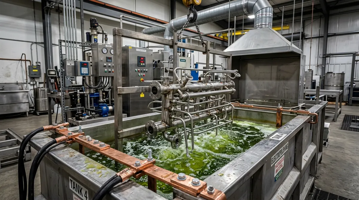
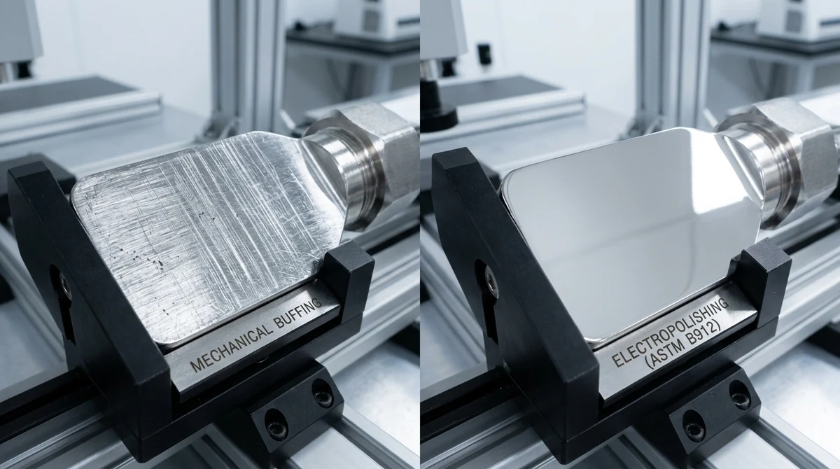
Electropolishing is widely recognized as the gold standard finishing method for austenitic stainless steel (304, 316L, 17-4PH) and titanium medical hardware. Unlike mechanical buffing, which relies on abrasive shear friction that can embed abrasive grit and introduce cold-work residual stresses, electropolishing is a non-contact electrochemical dissolution process.
3.1 Faraday’s Dissolution Kinetics
The metal workpiece acts as the positive anode submerged in a heated electrolyte bath (a concentrated mixture of 65% to 75% orthophosphoric acid, H3PO4, and 15% to 25% sulfuric acid, H2SO4). Cathode plates (lead or stainless steel) complete the electrical circuit. When direct electrical current (DC) is applied, metal mass dissolution (Δm) is governed by Faraday’s Law of Electrolysis:
Where I is total electrical current (Amperes), t is immersion duration (seconds), Mmolar is atomic molar mass of the dissolving alloy (g/mol), n is electrochemical valence (e.g., Fe2+, Cr3+, Ni2+), and F is the Faraday constant (96,485 C/mol).
3.2 Peak-to-Valley Current Density Concentration
The microscopic leveling effect occurs because a heavy, high-viscosity boundary layer of dissolved metal salts forms immediately adjacent to the anode surface. This boundary layer exhibits higher electrical resistivity than the bulk electrolyte bath. Because microscopic surface peaks (asperities) protrude higher into the thinner portion of the resistive film, the local electrical gradient and current density at the peaks (Jpeak) are significantly higher than in the valleys (Jvalley):
Consequently, microscopic peaks dissolve at 2 to 4 times the rate of adjoining valleys. The surface planarizes into an ultra-smooth, mirror finish without introducing mechanical stress. Furthermore, electropolishing preferentially extracts iron atoms from stainless steel matrices, creating a chromium-enriched surface oxide layer (Cr/Fe ratio ≥ 1.5 to 2.0) that dramatically boosts pitting and crevice corrosion resistance in saline and chemical environments.
4. SPI Mold Finish Standards & Abrasive Step Sequences
The Society of the Plastics Industry (SPI) defines twelve standardized surface finish classifications for injection mold tooling and precision machined parts. Achieving each classification demands a strictly controlled, multi-step abrasive progression.
| SPI Grade | Finishing Method | Abrasive Media Sequence | Target Roughness | Visual Characteristic |
|---|---|---|---|---|
| SPI A-1 | Grade #3 Diamond Paste Buff | Progress to 1 μm & 0.25 μm diamond rouge | Ra 0.012 to 0.025 μm | Optically pure, zero-haze mirror |
| SPI A-2 | Grade #6 Diamond Paste Buff | Progress to 3 μm diamond compound | Ra 0.025 to 0.050 μm | High-gloss mirror finish |
| SPI A-3 | Grade #15 Diamond Paste Buff | Progress to 6 μm diamond paste | Ra 0.050 to 0.100 μm | Semi-gloss mirror finish |
| SPI B-1 | Fine Grit Paper Polish | 600 Grit Silicon Carbide Paper | Ra 0.05 to 0.10 μm | Fine satin paper finish |
| SPI B-2 | Medium Grit Paper Polish | 400 Grit Silicon Carbide Paper | Ra 0.10 to 0.15 μm | Medium paper finish |
| SPI B-3 | Coarse Grit Paper Polish | 320 Grit Silicon Carbide Paper | Ra 0.20 to 0.28 μm | Standard paper finish |
| SPI C-1 / C-2 / C-3 | Stone Polishing Stoning | 600 / 400 / 320 Grit Stoning Stones | Ra 0.35 to 0.80 μm | Matte non-directional stone texture |
| SPI D-1 / D-2 / D-3 | Dry Media Bead Blasting | Glass Bead / #24 Aluminum Oxide Blast | Ra 0.80 to 3.20 μm | Uniform matte non-reflective texture |
5. Step-by-Step Diamond Polishing Protocol for Mold Tooling
Achieving an SPI A-1 optical mirror finish on pre-hardened mold steels (such as NAK80 or ESR-grade S136 hardened to 48 to 52 HRC) requires a meticulous, 5-stage progressive polishing protocol.
Step 1: Recast Layer Removal & Pre-Stoning
If the cavity was machined via wire or sinker EDM, a brittle, micro-cracked “recast white layer” (10 to 25 μm thick) covers the steel. Technicians initiate stoning using 220-grit aluminum oxide stones lubricated with kerosene or mineral stoning oil. Stoning continues until all EDM spark pits and CNC scallop marks are completely abraded away.
Step 2: Progressive Fine Stoning (320 → 400 → 600 Grit)
Technicians progress through 320, 400, and 600 grit stones. Critical Rule of Orthogonal Stroke Alternation: At each grit change, the polishing stroke direction must be rotated by 45 to 90 degrees relative to the prior grit marks. This ensures that deeper scratch patterns from the previous coarser grit are immediately visible and thoroughly eradicated before stepping down to finer media.
Step 3: Silicon Carbide Micro-Paper Sanding (800 → 1200 → 2000 Grit)
Transition from rigid stones to flexible waterproof silicon carbide micro-paper mounted on softwood sticks or contoured rubber blocks. Light, consistent manual pressure is applied using oil lubricant to float away loose swarf. By the end of 2000-grit sanding, the mold face exhibits a uniform semi-gloss sheen (Ra approx. 0.05 μm) with no directional gouges.
Step 4: Diamond Paste Lapping (6 μm → 3 μm)
Progress to polycrystalline diamond compound suspended in water-soluble oil carriers. Diamond compound is applied via hard balsa wood or laminated hornbeam laps driven by reciprocating ultrasonic polishing handpieces. The rigid wood backing holds the diamond particles firmly, preventing them from rolling and cleanly shearing micro-peaks.
Step 5: Final SPI A-1 Mirror Rouge Buffing (1 μm → 0.25 μm)
The final optical mirror is generated using 1-micron and 0.25-micron diamond compound on soft, virgin merino felt bobs or rotating flannel wheels operating at low speeds (under 3,000 RPM). Polishers apply light “feathering” strokes. Thorough ultrasonic solvent degreasing is executed between every stage to ensure a single stray 600-grit abrasive grain does not contaminate the 1-micron diamond felt, which would instantly destroy hours of delicate mirror polishing.
6. Forensic Failure Analysis of Polishing Defects
When polishing hard tooling steels or ductile aluminum alloys, technicians frequently encounter metallurgical surface defects. Identifying root causes is essential to salvage components:
- Orange Peel (Surface Waviness):
- Symptom: A rippled, bumpy surface resembling the skin of an orange, destroying optical flatness.
- Root Cause: Over-polishing caused by excessive tool contact pressure and localized frictional heat buildup. Frictional overheating causes localized yielding along austenitic/martensitic grain boundaries in softer metals.
- Corrective Action: Strip back to 600-grit stoning to flatten the wavy profile. Re-polish using light, rapid strokes and high-lubricity diamond carriers.
- Pitting & Carbides Pull-Out:
- Symptom: Microscopic pinholes or craters distributed across an otherwise mirrored cavity.
- Root Cause: Non-metallic oxide inclusions or large chromium carbides plucked out of the steel matrix by overly aggressive diamond buffing or soft felt dwelling.
- Corrective Action: Utilize vacuum-degassed, electroslag-remelted (ESR) mold steels (e.g., Uddeholm Stavax ESR). Avoid excessive buffing time; use hard wooden laps rather than soft felt.
- Comet Tails (Streaking Trails):
- Symptom: A comet-like directional scratch trail originating from a hard inclusion particle.
- Root Cause: Polishing exclusively in a single unidirectional stroke, causing loose hard particles or inclusions to drag across the softer surrounding matrix.
- Corrective Action: Continuously vary stroke trajectory (figure-8 motion) and maintain immaculate cleanliness during abrasive step transitions.
7. Design for Polishing (DFP) Rules for Mechanical Engineers
Applying the following engineering principles during initial 3D CAD design substantially reduces manual polishing costs and guarantees accessible tool paths:
Rule 1: Provide Generous Internal Corner Radii (R ≥ 3.0 mm)
Sharp internal 90-degree corners cannot be reached by rotary polishing wheels, ultrasonic stones, or felt bobs. Polishers are forced to hand-dress tiny needle files, multiplying labor hours by 5×. Specify internal corner fillets of R 3.0 mm to 5.0 mm whenever an SPI-A1 or A-2 finish is required.
Rule 2: Split Complex Optical Cavities into Modular Inserts
Polishing deep, narrow blind cavities (depth-to-width ratio > 2:1) is nearly impossible to perform uniformly. Split deep optical cavities into two-piece modular inserts along the parting line. This allows polishers to work on open, accessible exterior faces on high-speed lapping plates before final tool assembly.
Rule 3: Factor in Electropolishing Stock Removal Allowances
Electropolishing removes 10 to 25 μm (0.010 to 0.025 mm) of metal per surface. While beneficial for deburring, this dimensional loss will enlarge precision bearing bores and loosen Class 2B/3B internal threads. Machine critical datums with negative offset allowances or specify protective silicone masking plugs prior to electropolishing.
Frequently Asked Questions
Mechanical buffing uses abrasive shear friction and microscopic cutting to mechanically level surface peaks, which can leave directional scratches and cold-work surface stresses. Electropolishing is a non-contact electrochemical process where metal ions dissolve preferentially from micro-peaks, producing a completely stress-free, passivated, mirror-smooth surface.
Electropolishing typically removes between 10 and 25 microns (0.010 to 0.025 mm) of surface metal. Critical bearing journals, dowel holes, and close-tolerance threads must be machined with dimensional compensation allowances or masked with silicone plugs.
Orange peel is a wavy surface defect caused by over-polishing with excessive contact pressure and frictional heat, which induces localized grain yielding in the alloy. It is corrected by stripping the surface back with 600-grit stoning to restore flatness and finishing with light, rapid diamond strokes.
SPI A-1 is the highest plastic mold finish, achieving a roughness of Ra 0.012 to 0.025 microns (12 to 25 nanometers). It is achieved using progressive 3-micron, 1-micron, and 0.25-micron diamond compound on virgin felt bobs to create an optically pure mirror.
Engineering DFM reviews and finishing quotes are delivered within 24 hours. Batch vibratory mass finishing and stainless steel electropolishing runs ship in 4 to 8 business days, while intricate SPI A-1 optical injection mold cavity benching ships in 7 to 12 business days.
Need High-Precision Metal Polishing or Electropolishing?
AS Prototypes delivers optical SPI A-1 diamond mold polishing, high-purity ASTM B912 stainless steel electropolishing, and automated mass vibratory deburring. Upload your 3D CAD files today for comprehensive DFM surface finishing analysis and an engineering quote within 24 hours.
Request Surface Finishing Quote & DFM Review