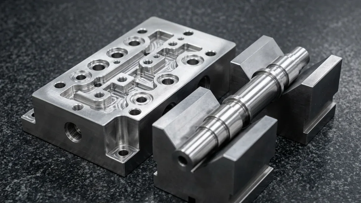
In high-stress aerospace structural components, surgical orthopedic tools, and high-pressure fluid manifolds, standard austenitic grades such as 304 and 316 frequently fall short of mechanical yield requirements. 17-4 PH stainless steel (UNS S17400 / AISI 630 / DIN 1.4542) stands as the premier martensitic precipitation-hardening alloy, combining tensile yield strengths exceeding 1170 MPa with corrosion resistance comparable to 304.
However, for manufacturing engineers and shop-floor CNC programmers, 17-4 PH presents distinct machining challenges. Its high shear strength, tendency toward rapid work-hardening, and metallurgical volume contraction during post-machining heat treatment demand disciplined machining strategies. This comprehensive engineering guide outlines material metallurgy, heat treatment trade-offs, optimized cutting speeds and feeds, tool coating choices, and dimensional compensation protocols applied at our precision CNC machining facility.
- Core Focus & DFM Scope: Actionable shop-floor engineering guidelines for 17-4 PH stainless steel machining, covering material selection, geometric tolerancing, and defect prevention.
- Achievable Tolerance Envelope: General features hold ISO 2768-mK; critical bearing bores, dowel pins, and mating datums hold ±0.010 to ±0.020 mm (±0.0004″ to ±0.0008″), with Wire EDM/grinding to ±0.005 mm (±0.0002″).
- Machining & Surface Integrity: High-speed 3-axis and 4-axis VMCs (with simultaneous 5-axis for complex contours) delivering as-machined Ra 0.8 µm (32 µin) to Ra 0.4 µm (16 µin) per ASME B46.1.
- Metrology & Process Control: On-machine spindle probing paired with 20°C (68°F) climate-controlled Zeiss CMM coordinate verification and calibrated Go/No-Go plug/ring gauges.
- Ex-Factory Turnaround: 4 to 8 business days for as-machined rapid prototypes; 7 to 12 business days for anodized, plated, or multi-operation production runs (excluding 3–5 days air transit).
1. Metallurgical Overview: Why 17-4 PH Requires Specialized Machining
17-4 PH is formulated with approximately 15.0–17.5% Chromium, 3.0–5.0% Nickel, 3.0–5.0% Copper, and 0.15–0.45% Columbium (Niobium). The copper additions precipitate sub-microscopic copper-rich spherical particles throughout the martensitic matrix during aging heat treatments, substantially elevating hardness and tensile strength without inducing brittle fracture behavior.
Unlike standard 300-series stainless steels that remain austenitic and work-harden primarily under plastic tool strain, 17-4 PH exhibits a martensitic microstructure even in its unhardened state. When cutting tool friction generates localized shear zone temperatures exceeding 650°C, built-up edge (BUE) and notch wear accelerate rapidly unless high-pressure cutting fluids and high-shear rake geometries are applied.
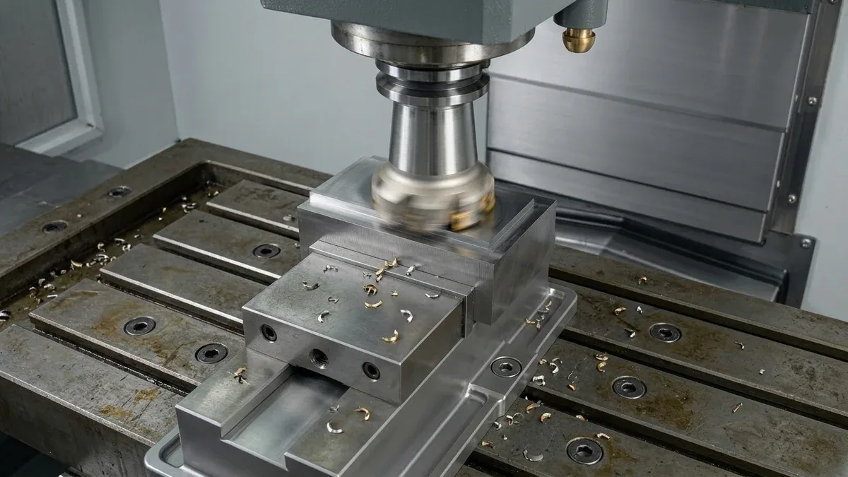
2. Heat Treatment Conditions vs. Machinability Matrix
The primary strategic decision when manufacturing 17-4 PH components is determining whether to cut the workpiece in Condition A (Solution Annealed) or in an Aged (Precipitation-Hardened) Condition. Each route involves specific trade-offs in cutter longevity, surface roughness, and dimensional stability:
- Condition A (Annealed at 1040°C, Air-Cooled): Hardness averages ~30–35 HRC. The material is relatively ductile but gummy. Continuous chips tend to bird-nest around toolholders, with higher risk of burr formation at workpiece breakout edges.
- Condition H900 (Peak Hardness Aged at 482°C): Hardness peaks at 40–47 HRC with ultimate tensile strength around 1380 MPa. Chips break cleanly, but cutting forces spike by 35–45%, requiring rigid multi-axis clamping and reduced surface cutting speeds.
- Overaged Conditions (H1025, H1150, H1150-M): Offer superior fracture toughness and stress-corrosion resistance at moderate hardness (28–38 HRC), delivering the most balanced overall machinability among hardened states.
| Condition | Aging Temp | Hardness (HRC) | Yield Strength | Aging Contraction | Carbide Milling Speed (Vc) |
|---|---|---|---|---|---|
| Condition A (Annealed) | 1040°C Solution | 30–35 HRC | 760 MPa (110 ksi) | Baseline Datum | 90–130 m/min (295–425 SFM) |
| Condition H900 (Peak Aged) | 482°C (900°F), 1 hr | 40–47 HRC | 1170 MPa (170 ksi) | 0.0004–0.0006 mm/mm | 55–80 m/min (180–260 SFM) |
| Condition H1025 | 552°C (1025°F), 4 hr | 35–42 HRC | 1000 MPa (145 ksi) | 0.0005–0.0007 mm/mm | 75–105 m/min (245–345 SFM) |
| Condition H1150 (Overaged) | 621°C (1150°F), 4 hr | 28–37 HRC | 725 MPa (105 ksi) | 0.0008–0.0010 mm/mm | 95–135 m/min (310–440 SFM) |
Crucial Engineering Phenomenon: Precipitation Aging Shrinkage
When 17-4 PH is rough-machined in Condition A and subsequently aged to H900, the precipitation of the copper-rich phase produces predictable dimensional shrinkage of approximately 0.0004 to 0.0006 mm/mm (0.04% to 0.06%). When aging to Condition H1150, contraction increases to 0.0008 to 0.0010 mm/mm (0.08% to 0.10%).
At AS Prototypes, our manufacturing engineers apply a two-stage routing protocol for parts requiring tolerances tighter than ±0.015 mm: roughing and semi-finishing in Condition A leaving a +0.25 mm stock allowance, performing controlled vacuum age-hardening, and completing final precision grinding or finish CNC milling to achieve verified tolerances down to ±0.005 mm.
3. Recommended Feeds, Speeds, and Tooling Specifications
Achieving stable tool life when milling or CNC turning 17-4 PH requires rigid tool clamping, sub-micron tungsten carbide substrates, and advanced physical vapor deposition (PVD) coatings capable of resisting thermal shock and edge chipping.
- Carbide Substrate & Coating: Multi-layer PVD AlTiN (Aluminum Titanium Nitride) or nanocomposite TiAlSiN coatings provide exceptional surface lubricity and oxidation resistance up to 900°C, significantly outperforming standard CVD coatings.
- Cutter Geometry: Positive rake angles (6° to 10°) are essential to reduce cutting resistance and deformation heat, paired with reinforced hone edge preps (0.015–0.025 mm) to prevent micro-chipping during interrupted cuts.
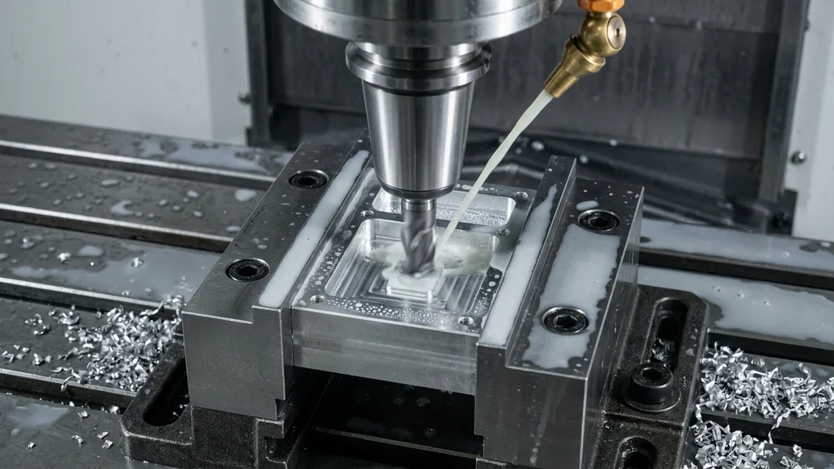
- Coolant Strategy: High-pressure through-spindle coolant (70 bar / 1000 psi) or flooding with 8–10% concentration semi-synthetic emulsion is critical for thermal stabilization and chip evacuation. Intermittent coolant must be avoided, as thermal cycling causes carbide micro-fracturing.
4. Drilling, Threading, and Preventing Work-Hardening
Drilling and thread tapping in 17-4 PH can lead to rapid tool failure if the cutter is permitted to dwell against the cut surface. Never allow a drill or end mill to rotate without positive chip engagement; tool rubbing immediately generates a work-hardened white layer with surface hardness exceeding 55 HRC, leading to premature tap breakage.
- Peck Drilling Cycles: For hole depths exceeding 3x diameter (3D), utilize a programmed peck cycle with full retract to flush out curled swarf. Ensure chips break into short needles rather than continuous ribbons.
- Thread Milling vs Tapping: For internal threads M6 and larger in Condition H900 or H1025, thread milling is strongly preferred over cut taps. Thread milling reduces cutting torque, guarantees Class 6H or 2B/3B thread fit precision, and eliminates the risk of an unremovable broken tap inside a high-value machined component.
5. Post-Machining Passivation and Quality Verification
Although 17-4 PH exhibits excellent resistance to atmospheric and mild acidic oxidation, free iron contamination from carbide cutting tools or grinding wheels can embed into the workpiece surface, potentially causing localized pitting in humid or marine environments.
All precision 17-4 PH components produced at AS Prototypes undergo chemical passivation per ASTM A967 (Nitric or Citric Acid Method) or AMS 2700 standards. Passivation dissolves residual surface iron and promotes the rapid formation of a self-healing, passive chromium oxide barrier without altering tight tolerances.
Dimensional compliance is validated inside our climate-controlled (20°C ± 0.5°C) inspection lab using Zeiss Coordinate Measuring Machines (CMM), surface roughness profilometers verifying finishes down to Ra 0.4 µm, and calibrated pneumatic bore micrometers. Comprehensive First Article Inspection Reports (FAIR) and raw material test reports (MTR) can be provided with production shipments upon request.
Why Do 17-4 Ph Stainless Steel Machining Components Fail Tight Tolerances in Production, and How Do You Prevent It?
Maintaining repeatable accuracy in 17-4 PH stainless steel machining requires controlling radial tool deflection, internal residual stress relaxation, and thermal expansion drift across multi-axis setups. While general unmated features reliably conform to ISO 2768-mK, holding critical mating bores and datum surfaces within ±0.010 mm (±0.0004″) demands staged roughing-to-finishing stress relief and rigid workholding.
Shop-Floor Quantitative Derivation: Cantilever Tool Deflection & Thermal Drift Compensation
In our Shenzhen CNC machine shop, preventing wall taper and bore bell-mouthing in 17-4 PH stainless steel machining begins with calculating cantilever end-mill deflection (δ) before releasing G-code to the spindle. Modeled as a cylindrical carbide beam of diameter D and stickout length L subjected to radial cutting force Fr, tool deflection follows the fourth-power stiffness law:
δ = (64 × Fr × L³) / (3 × π × E × D⁴)
For a solid carbide end mill (E = 600 GPa / 87,000 ksi) with diameter D = 8.0 mm (0.315″), stickout L = 36 mm (4.5×D), and radial cutting load Fr = 180 N (40.5 lbf), the resulting deflection is δ = (64 × 180 × 36³) / (3 × 3.1416 × 600,000 × 4,096) = 0.0232 mm (0.00091″)—instantly consuming a ±0.010 mm (±0.0004″) drawing tolerance! By stepping up to a D = 10.0 mm (0.394″) corner-radius tool and reducing stickout to L = 28 mm (2.8×D) with a 0.15 mm (0.006″) semi-finishing spring pass (Fr = 45 N), radial deflection drops to δ = 0.0011 mm (0.00004″), locking true position and cylindricity well within print limits.
Step-by-Step Shop-Floor Execution & Quality Protocol
To bridge CAD intent with repeatable shop-floor delivery, our engineering team enforces a four-stage execution workflow across every prototype and low-volume production batch:
- Step 1: Datum Hierarchy & 3/4/5-Axis Workholding Design: Align primary, secondary, and tertiary GD&T datums (A-B-C) with precision Kurt vises, custom-contoured 6061 aluminum soft jaws, or zero-point pneumatic pallets to minimize re-clamping datum shift.
- Step 2: Roughing & Intermediate Stress-Relief Stabilization: Execute high-efficiency trochoidal roughing leaving 0.30 to 0.50 mm (0.012″ to 0.020″) uniform stock, followed by unclamping or thermal stress-relief stabilization to release rolled-billet internal tension.
- Step 3: On-Machine Probing & Climate-Controlled Finishing: Re-probe work coordinate offsets via infrared spindle touch probes in a 20°C (68°F) shop environment, then execute climb-milling finish passes to achieve Ra 0.4–0.8 μm (16–32 μin).
- Step 4: Zeiss CMM Verification & Surface Treatment Masking: Perform first-article and batch inspection on programmable Zeiss CMM systems, applying silicone plugs to H7 bores and tapped threads prior to MIL-A-8625 anodizing or ASTM A967 passivation.
Shop-Floor Defect Troubleshooting & Corrective Action Matrix
When evaluating part geometry during pre-production DFM review, our manufacturing engineers screen for the following failure modes and apply proven corrective controls:
| Defect / Symptom | Physical Root Cause | Shop-Floor Corrective Action | Recommended DFM Spec Limit |
|---|---|---|---|
| Thin-Wall Warpage & Bowing | Asymmetric removal of rolled skin releasing internal residual stress or excessive clamping jaw pressure | Alternate roughing passes symmetrically across both sides, leave 0.4 mm stock for stress relaxation, and finish-mill in low-pressure contoured soft jaws. | Flatness ≤ 0.02 mm / 100 mm |
| Deep Pocket Wall Taper & Chatter | Tool stickout exceeding L/D > 4:1 causing harmonic regeneration and radial tool push-off | Maximize internal corner radii (R ≥ 1/3 cavity depth) to permit larger-diameter stubby carbide tools and apply variable-helix climb milling. | Optimal pocket L/D ≤ 4:1 |
| Bore Out-of-Roundness (3-Lobing) | Three-jaw chuck clamping distortion on thin-walled rings or thermal spindle growth | Switch to full-wrap pie jaws or vacuum fixtures, execute a zero-offset spring boring pass, and verify with air/plug gauges before unclamping. | Cylindricity ≤ 0.008 mm |
| Post-Coating Thread / Bore Binding | Failure to account for 10–50 μm (0.4–2.0 mil) dimensional buildup from Type II/III anodizing or electroless nickel | Mask critical H7 bores with silicone plugs or pre-machine pitch/bore diameters oversize by 2× coating thickness per surface. | Masking on tolerances ≤ ±0.02 mm |
Engineering Trade-Offs: When NOT to Over-Specify
When to Avoid Over-Specifying (Engineering Cost-Tolerance Trade-Offs): Never apply blanket ±0.005 to ±0.010 mm (±0.0002″ to ±0.0004″) tolerances or simultaneous 5-axis callouts across non-mating exterior surfaces and clearance brackets. Tightening a non-critical feature from standard ISO 2768-mK (±0.10 to ±0.20 mm) to ±0.010 mm increases cycle time and inspection overhead by 2.0× to 3.5× due to mandatory semi-finishing passes, thermal soak cycles, and 100% CMM probing. Reserve tight tolerances strictly for functional bearing journals, dowel pins, and sealing faces, while letting 3-axis and 4-axis VMCs handle prismatic geometry efficiently.
🔗 Related CNC DFM & Metrology Engineering Guides:
To further optimize cycle time and dimensional stability in 17-4 PH stainless steel machining, combine proper internal corner relief with datum-based coordinate inspection. Consult our shop-floor engineering guides on Maintaining Dimensional Stability in Thin-Wall Machining, Eliminating Sharp Internal Corners & Tool Deflection, and Precision CMM Metrology & GD&T Verification.
Frequently Asked Questions (FAQ)
For parts requiring tight tolerances (< ±0.015 mm) or deep complex cavities, the recommended engineering route is rough-machining in Condition A with +0.25 mm stock allowance, performing age-hardening heat treatment (such as H900 or H1150), and finish-machining or grinding to final dimensions. This eliminates the risk of aging shrinkage (0.05% to 0.10%) causing distortion. For broader tolerances, pre-hardened material (H1150) can be machined directly.
The primary failure modes are thermal crater wear from localized cutting heat and notch wear at the depth-of-cut line caused by the work-hardened boundary layer. Both are mitigated by selecting AlTiN/TiAlSiN PVD-coated micro-grain carbide tooling, maintaining continuous positive chip load (avoiding tool dwell), and directing high-pressure coolant (70 bar) directly into the shear zone.
17-4 PH provides more than triple the yield strength and double the hardness of 316L stainless steel, making it vastly superior for shafts, gears, and high-pressure components subject to mechanical deflection. While 316L offers higher resistance in aggressive marine chloride environments, 17-4 PH delivers cleaner chip fracturing and superior surface finishes in CNC turning and milling.
Partner with AS Prototypes for High-Precision 17-4 PH Machining
From complex aerospace brackets and downhole fluid valve manifolds to custom orthopedic surgical prototypes, AS Prototypes delivers precision turnkey manufacturing in 17-4 PH stainless steel. Our in-house manufacturing capabilities integrate CNC turning, high-speed 3-axis, 4-axis and 5-axis milling, surface grinding, controlled vacuum heat treatment, ASTM A967 passivation, and comprehensive Zeiss CMM metrology verification.
Need Precision 17-4 PH Stainless Steel Parts?
Upload your 3D CAD models (STEP, STP, or IGES) and 2D dimensional drawings. Our senior engineering team will provide a thorough DFM machinability assessment, heat treatment shrinkage allowance plan, and quote.
✓ Controlled Heat Treat & ASTM Passivation
✓ Zeiss CMM Dimensional Inspection