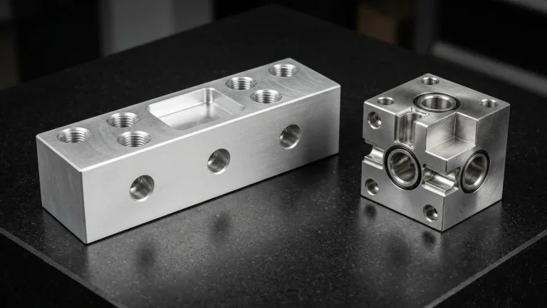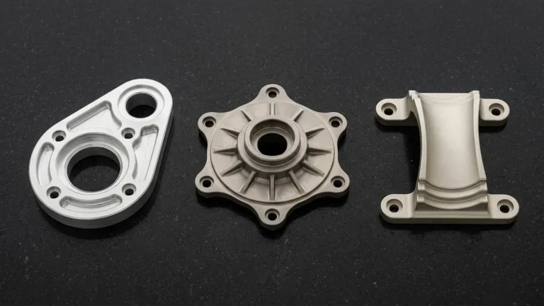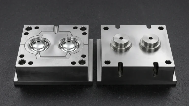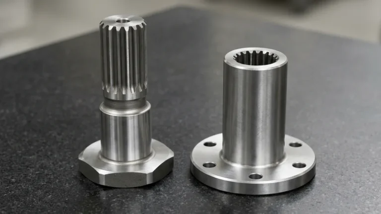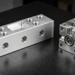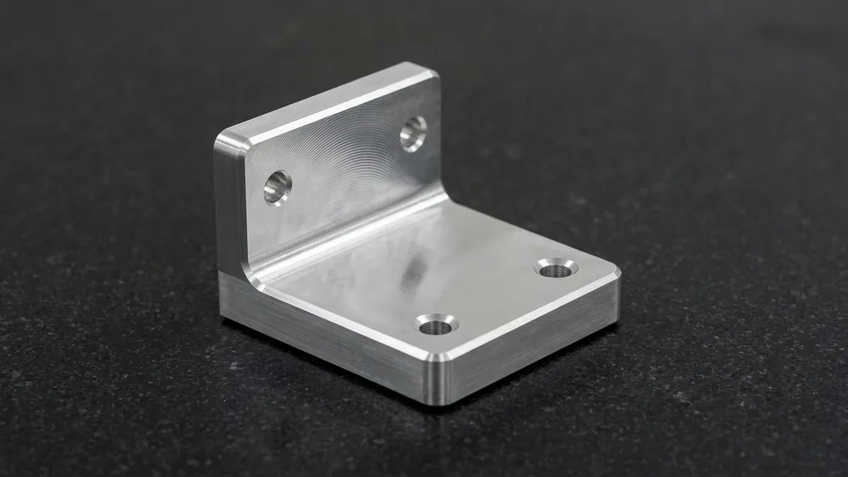
In mechanical engineering and precision contract manufacturing, few geometric specifications are as ubiquitous—or as frequently misunderstood—as perpendicularity in GD&T. Defined within the foundational frameworks of ASME Y14.5-2018 and ISO 1101, perpendicularity (symbolized by the inverted right-angle character ⟂) governs the exact 90-degree orthogonal relationship between a controlled feature and a specified reference datum.
Whether assembling aerospace structural brackets, locating precision guide pins in high-speed stamping dies, or boring high-speed spindle housings, non-conforming squareness introduces severe operational consequences. An angular misalignment of merely 0.02 mm over a 150 mm span can cause catastrophic bearing edge-loading, premature seal degradation, hydraulic spool binding, and severe vibration under dynamic mechanical loads. At AS Prototypes, holding perpendicularity down to 0.010 mm is achieved through high-rigidity 3-axis, 4-axis, and 5-axis CNC machining, rigorous spindle tramming, and coordinate metrology verification.
- 1. What is Perpendicularity in GD&T? Symbology & Feature Control Frame
- 2. Types of Perpendicularity Tolerances: Surface vs. Axis vs. Center Plane
- 3. Material Condition Modifiers: MMC, LMC & Bonus Tolerance
- 4. Engineering Comparison: Perpendicularity vs. Related GD&T Controls
- 5. Shop-Floor Metrology: How Perpendicularity is Measured & Verified
- 6. CNC Machining Strategies: Achieving Tight Perpendicularity (0.010 mm)
- 7. Technical Engineering FAQ
1. What is Perpendicularity in GD&T? Symbology & Feature Control Frame
Perpendicularity is categorized as an orientation tolerance. Unlike dimensional plus-minus angular tolerances (±0.5°), which define an expanding angular wedge where allowable deviation grows proportionally with distance from the pivot vertex, GD&T perpendicularity creates a strict, uniform tolerance boundary across the entire functional zone.
Furthermore, perpendicularity controls orientation and form, but does not control the spatial position or location of the feature. To properly interpret perpendicularity callouts on engineering blueprints, engineers examine the Feature Control Frame (FCF):
- Geometric Characteristic Symbol: The perpendicularity symbol (⟂), denoting a mandatory 90.000° basic relationship.
- Tolerance Zone Descriptor & Value: Specifies the width or diameter of the allowable boundary (e.g.,
0.02for planar zones, orØ0.05for cylindrical zones). - Material Condition Modifier: Specifies whether the tolerance applies Regardless of Feature Size (
RFS, default) or at Maximum Material Condition (MMC / Ⓜ), which introduces bonus tolerance. - Primary & Secondary Datum References: Identifies the datum plane, axis, or center plane against which the 90-degree relationship must be maintained (e.g.,
[⟂ | 0.015 | A | B]).
2. Types of Perpendicularity Tolerances: Surface vs. Axis vs. Center Plane
Depending on whether the controlled element is a planar face, an axis of a cylinder, or the center plane of a feature of size, the geometry of the perpendicularity tolerance zone changes fundamentally.
1. Surface Perpendicularity (Planar Features)
Surface perpendicularity controls the orientation of a flat surface relative to a datum plane. The tolerance zone consists of two parallel planes separated by the specified tolerance value (t), oriented exactly 90 degrees to the reference datum plane.
Every physical peak and valley on the controlled surface must lie entirely within these two parallel boundaries. Notably, surface perpendicularity inherently refines and limits the flatness of the controlled feature; a surface cannot exhibit flatness error greater than its allowable perpendicularity tolerance.
2. Axis Perpendicularity (Cylindrical Holes & Shafts)
When perpendicularity is applied to a feature of size, such as a precision reamed dowel hole, bored cylinder, or turned locating boss, the tolerance zone is typically a cylinder of diameter Øt whose central axis is oriented perfectly perpendicular to the reference datum plane.
The derived median axis of the machined hole or shaft must remain entirely within this cylindrical envelope across the full feature depth. If the diameter symbol (Ø) is omitted, the tolerance zone defaults to two parallel planes, constraining axis tilt in a single defined direction.
3. Center Plane Perpendicularity (Slots & Tabs)
For non-cylindrical features of size, such as milled keyways, T-slots, or locating lugs, perpendicularity controls the median center plane of the feature between two parallel planes perpendicular to the primary datum axis or plane.
3. Material Condition Modifiers: MMC, LMC & Bonus Tolerance
In high-volume precision CNC manufacturing, applying material condition modifiers provides crucial design flexibility while protecting functional assembly requirements.
Regardless of Feature Size (RFS)
Under ASME Y14.5, RFS is the default condition when no modifier symbol is indicated. The stated perpendicularity tolerance must be honored strictly, regardless of where the physical feature diameter falls within its cross-sectional size limits. RFS is universally specified for high-speed dynamic rotating assemblies, press-fit bearings, and optical mounting surfaces.
Maximum Material Condition (MMC – Ⓜ) & Bonus Tolerance
When applied to clearance holes, guide pins, or bolt patterns, the MMC modifier allows the perpendicularity tolerance to expand as the actual feature departs from its maximum material boundary (smallest hole or largest pin). This additional allowable deviation is termed Bonus Tolerance:
Bonus Tolerance Formula for Internal Features (Holes):
Total Allowable Perpendicularity = Specified Tolerance + (Actual Milled Diameter – MMC Minimum Diameter)
For example, if a clearance hole is toleranced as Ø10.00 ±0.10 mm with a perpendicularity callout of [⟂ | Ø0.05 Ⓜ | A], the MMC state occurs at Ø9.90 mm with an allowable perpendicularity of Ø0.05 mm. If the machinist finishes the hole at Ø10.08 mm, a bonus tolerance of 0.18 mm is gained, permitting a total perpendicularity deviation of Ø0.23 mm while still guaranteeing bolt clearance through mating plates.
4. Engineering Comparison: Perpendicularity vs. Related GD&T Controls
To avoid over-constraining drawings or misinterpreting inspection criteria, manufacturing engineers compare perpendicularity against its sister orientation, form, and location tolerances:
5. Shop-Floor Metrology: How Perpendicularity is Measured & Verified
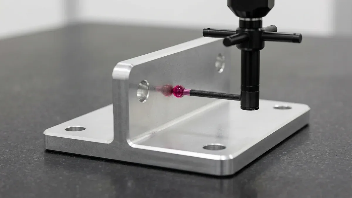
Reliable perpendicularity verification requires isolated thermal environments and calibrated metrology instruments conforming to ISO 10360 standards.
1. High-Precision Coordinate Measuring Machines (CMM)
Modern CNC machine shops rely on bridge or gantry CMMs equipped with high-accuracy tactile scanning probes (such as Zeiss VAST or Renishaw SP25M) to evaluate perpendicularity:
- Datum Alignment: The probe samples a dense grid of points across primary datum A to compute the true mathematical datum plane via Least Squares or Chebyshev minimum zone filtering.
- Feature Evaluation: The CMM touches multiple cross-sections of the controlled surface or cylindrical bore. The metrology software projects the derived feature vector against the datum normal vector and reports the exact peak-to-valley perpendicularity deviation in micrometers.
- Color Deviation Mapping: Full 3D scan mapping visualizes machining chatter, thermal taper, or cutter deflection along the length of the part.
2. Granite Surface Plate & Precision Cylindrical Master Square
For in-process quality control at the CNC machine station, machinists utilize a Grade 00 black granite surface plate and a hardened steel or granite master cylinder square:
- The machined workpiece rests on its primary datum face directly on the granite plate.
- A digital dial test indicator (0.001 mm resolution) mounted on a rigid transfer stand is zeroed against the calibrated vertical face of the master square.
- The indicator is brought into contact with the vertical face of the workpiece and swept continuously from bottom to top. The Total Indicator Reading (TIR) represents the total perpendicularity deviation across that span.
3. Dedicated Functional Go / No-Go Gauges
When an engineering drawing specifies perpendicularity at Maximum Material Condition (MMC / Ⓜ), custom-ground functional receiver pins and sleeve fixtures verify conformance in seconds. If the physical part engages the gauge freely without mechanical interference, the combined size and perpendicularity orientation comply with the functional envelope.
6. CNC Machining Strategies: Achieving Tight Perpendicularity (0.010 mm)
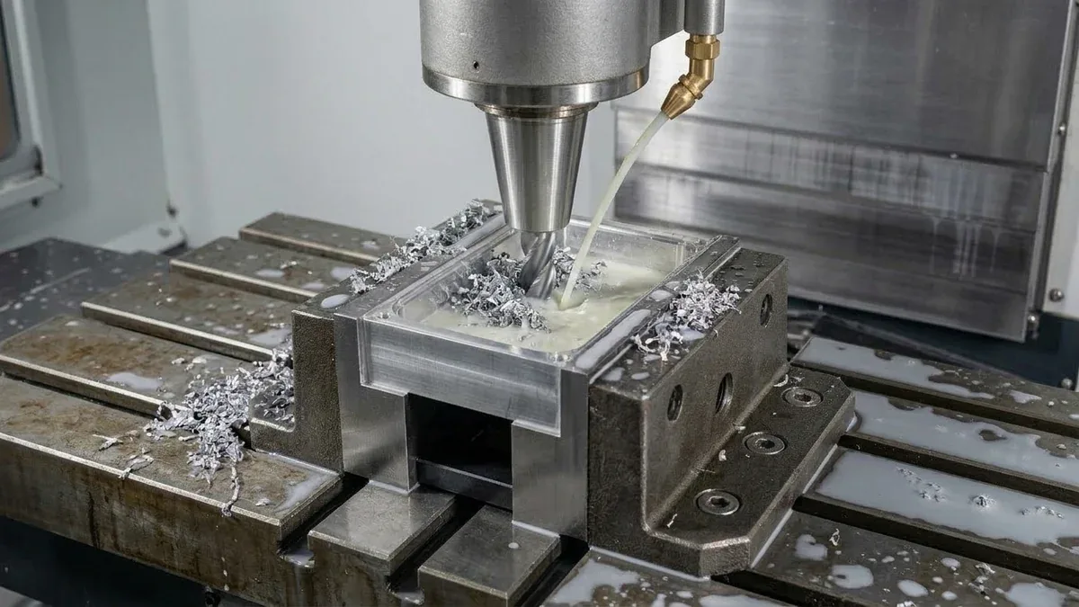
Achieving 0.010 mm (0.0004 in) squareness requires overcoming cutting tool deflection, fixture distortion, thermal drift, and machine kinematics errors. At AS Prototypes, our manufacturing engineering team deploys proven machining countermeasures:
1. Single-Setup 3+2 Indexed 5-Axis Machining
Traditional 3-axis CNC machining requires flipping the workpiece into a secondary vise to mill perpendicular faces. Every manual reclamping introduces fixture seat dirt, clamping torque variation, and vise jaw lift, easily causing 0.03 mm to 0.06 mm angular tilt. By utilizing 3+2 positional indexing on 5-axis machining centers, AS Prototypes machines the primary datum face, orthogonal reference faces, and precision bores in a single kinematic setup with locked rotary brakes, holding perpendicularity within a 0.010 mm (0.0004 in) tolerance zone consistently.
2. Precision Machine Spindle Tramming
Before critical squaring cuts, CNC operators verify machine spindle tramming using dual dial indicators mounted on an arbor arm rotated over a 300 mm diameter sweep. Spindle-to-table orthogonality is aligned to within 0.005 mm across 300 mm, preventing scalloped dish marks and concave surfaces during wide-face fly cutting.
3. Hydraulic Clamping & Stress Relief Protocols
High clamping force on asymmetric parts induces internal strain. When the vise is released after machining, elastic springback warps the 90-degree angle. We utilize:
- Torque-controlled hydraulic self-centering vises with custom soft jaws contoured to the part geometry.
- Multi-stage roughing cycles followed by unclamped room-temperature stress relaxation (12 to 24 hours for 7075-T651 to prevent over-aging above 110°C) or low-temperature thermal stress relief (150°C to 165°C for 6061-T6) and 316L stainless steel stabilization before final finishing skim cuts.
4. Toolpath Dynamics & Deflection Elimination
During deep vertical wall milling, cutting tool radial deflection causes tapered vertical walls that violate perpendicularity. We deploy large core-diameter solid carbide end mills with short overhang ratios (L/D < 3), balanced hydraulic tool holders, and separate semi-finishing and climb-milling finish passes with minimal radial engagement (Ae ≤ 0.1 mm) to eliminate tool push-off.
7. Technical Engineering FAQ
No. Perpendicularity is strictly an orientation control. It establishes the 90-degree angular relationship and form envelope relative to a datum, but it does not fix or limit where the feature is positioned in coordinate space. To control both location and orientation, engineers apply True Position (⌖) or composite feature control frames.
Yes. In multi-axis kinematic assemblies, a single cylindrical feature or slot may be required to maintain perpendicularity to multiple reference datums simultaneously. For instance, a bore may be specified perpendicular to primary datum plane A and secondary datum plane B to prevent spatial skewing across orthogonal planes.
Surface perpendicularity serves as an upper bound on surface flatness. Because all points of the controlled surface must reside within the two parallel planes of the perpendicularity tolerance zone, the flatness deviation of that surface can never exceed the specified perpendicularity tolerance value.
MMC should be specified whenever the primary functional requirement is clearance and physical assembly—such as clearance holes for fasteners, guide pins, and socket fittings. Specifying MMC permits bonus tolerance as holes expand or pins contract, substantially lowering manufacturing scrap and production costs without sacrificing assembly integrity.
Perpendicularity (ASME Y14.5) defines a tolerance zone bounded by two parallel planes perpendicular to a datum plane. It is measured using dial test indicators on precision granite squares or continuous CMM scanning.
Partner with Our Precision CNC Machining & Engineering Team
Eliminate tool deflection, residual stress distortion, and tolerance stack-up risks before production begins. Upload your 3D CAD files (STEP/IGES) and 2D GD&T drawings for a comprehensive shop-floor DFM review and custom quotation.
Upload 3D CAD for Engineering DFM & RFQ