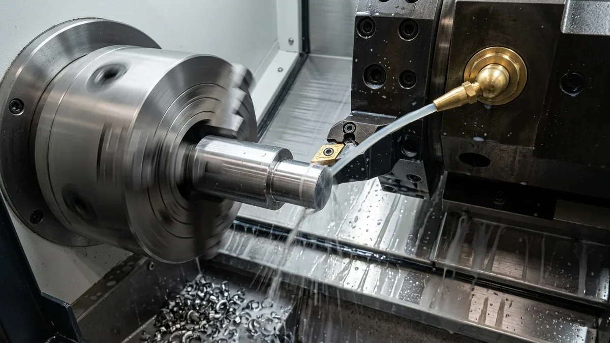
In precision subtractive manufacturing, few engineering metrics exert as decisive an influence over cutter longevity, surface roughness (Ra), and thermal chip equilibrium as Surface Feet per Minute (SFM). While modern CNC controllers accept rotational speed commands in revolutions per minute (RPM), cutting inserts and end mills do not experience RPM; they experience linear cutting velocity at the boundary layer where carbide shears metal.
Failing to understand the mathematical and thermal physics of SFM leads directly to premature insert wear, thermal tool fracturing, or costly production bottlenecks. In precision manufacturing, mastering sfm in machining ensures repeatable dimensional stability and predictable production scaling.
At AS Prototypes, our CNC milling and multi-axis turning engineers treat surface speed as a calibrated thermodynamic balance. Whether turning tough aerospace Grade 5 titanium (Ti-6Al-4V) shafts with G96 Constant Surface Speed or high-speed milling 6061-T6 aluminum optical chassis at elevated surface rates, dialing in the precise SFM window is essential to maintaining tight dimensional repeatability down to ±0.010 mm (±0.0004″).
In this technical guide, we break down the mathematical derivation of SFM, contrast it against metric cutting velocity (Vc), dissect G96 Constant Surface Speed in CNC turning, examine the thermal mechanics behind Taylor’s tool life law, and provide an industry-standard parameter reference matrix across engineering alloys.
Executive Summary & Engineering Takeaways (BLUF)
- Core Focus & DFM Scope: Actionable shop-floor engineering guidelines for sfm in machining, covering material selection, geometric tolerancing, and defect prevention.
- Achievable Tolerance Envelope: General features hold ISO 2768-mK; critical bearing bores, dowel pins, and mating datums hold ±0.010 to ±0.020 mm (±0.0004″ to ±0.0008″), with Wire EDM/grinding to ±0.005 mm (±0.0002″).
- Machining & Surface Integrity: High-speed 3-axis and 4-axis VMCs (with simultaneous 5-axis for complex contours) delivering as-machined Ra 0.8 µm (32 µin) to Ra 0.4 µm (16 µin) per ASME B46.1.
- Metrology & Process Control: On-machine spindle probing paired with 20°C (68°F) climate-controlled Zeiss CMM coordinate verification and calibrated Go/No-Go plug/ring gauges.
- Ex-Factory Turnaround: 4 to 8 business days for as-machined rapid prototypes; 7 to 12 business days for anodized, plated, or multi-operation production runs (excluding 3–5 days air transit).
Article Engineering Navigation
- 1. What is SFM? The Kinematics of Peripheral Cutting Speed
- 2. Constant Surface Speed (G96) vs. Constant RPM (G97) in CNC Turning
- 3. Thermal Partitioning and Taylor's Tool Life Law in SFM
- 4. Engineering Reference Matrix: Standard SFM Ranges by Material
- 5. Engineering Case Study: Stepped Titanium Aerospace Sensor Housing
- 6. Machinists' Diagnostic Checklist: Diagnosing Surface Speed from Chips and Inserts
- 7. Technical Engineering FAQ
1. What is SFM? The Kinematics of Peripheral Cutting Speed
Surface Feet per Minute (SFM) represents the linear distance (in feet) that a single point on the circumference of a rotating cutting tool (in milling) or a rotating workpiece (in turning) travels in exactly one minute. It is the Imperial measure of cutting velocity.
The core conceptual distinction to master is the relationship between angular velocity and peripheral velocity:
SFM = (π · Dinch · N) / (12) ≈ 0.2618 · Dinch · N
Where:
• SFM = Surface Feet per Minute (ft/min)
• Dinch = Tool Diameter (in milling) or Part Diameter (in turning) in inches
• N = Spindle Speed in Revolutions per Minute (RPM)
• 12 = Conversion factor converting inches to feet (π / 12 ≈ 0.261799)
Converting SFM to Spindle RPM (N)
Because CNC machine spindles are commanded in revolutions per minute, programmers must transpose the formula to solve for N:
The constant 3.82 (12 / π ≈ 3.8197) is the universal rule-of-thumb multiplier utilized by machinists across North America and international Imperial job shops to rapidly calculate required spindle RPM on the shop floor.
Imperial SFM vs. Metric Cutting Speed (Vc)
In metric manufacturing regions adhering to ISO standards, cutting speed is expressed as Vc (meters per minute, m/min). The mathematical relationship and conversion factors are straightforward:
SFM = Vc × 3.28084 ⇔ Vc = SFM × 0.3048
For example, a high-speed aluminum finishing operation running at Vc = 450 m/min translates directly to 450 × 3.28084 ≈ 1,476 SFM.

2. Constant Surface Speed (G96) vs. Constant RPM (G97) in CNC Turning
While in CNC milling the tool diameter (D) remains constant during a given cut, in CNC turning operations the workpiece diameter (D) dynamically changes as the tool traverses across the part. This geometric reality creates a vital distinction between programming modes:
1. Constant Spindle Speed (G97)
Under G97 S1200 M03, the machine spindle rotates at a fixed 1,200 RPM regardless of the tool’s radial position (X). If facing a Ø 4.0” billet down to Ø 0.5”:
- At the outer diameter (Ø 4.0”): SFM = 0.2618 × 4.0 × 1200 ≈ 1,256 SFM;
- At the mid-point (Ø 1.5”): SFM = 0.2618 × 1.5 × 1200 ≈ 471 SFM;
- Near the center pip (Ø 0.1”): SFM = 0.2618 × 0.1 × 1200 ≈ 31 SFM.
As the tool approaches the centerline, cutting velocity plummets towards zero. The cutting mechanism ceases to cleanly shear the metal; instead, it tears and smears the material, creating an uneven surface finish (Ra > 3.2 μm), massive burrs, and severe Built-Up Edge (BUE) on the carbide nose radius.
2. Constant Surface Speed (G96)
By activating G96 S600 M03, the CNC controller dynamically alters spindle speed in real time as the X-axis tool slide moves. As the tool moves inward toward smaller diameters, the spindle continuously accelerates to maintain exactly 600 SFM throughout the entire facing pass:
N(X) = (3.82 × SFM) / (2 · Xradius)
The Critical Safety Protocol: G50 Spindle Speed Clamping
Because the theoretical RPM required to maintain constant SFM approaches infinity as X → 0, executing G96 without a maximum ceiling clamp is hazardous. Without restriction, the spindle will accelerate to the machine’s maximum mechanical limit, leading to catastrophic chuck jaw centrifugal force decay, part ejection, or spindle motor over-current trip.
Every professional CNC turning program must establish an explicit spindle clamp using G50 (or G92 on certain controllers):
O0102 (TITANIUM SHAFT FACING & OD TURN)G20 G40 G99 (Inch, Cancel Cutter Comp, Feed Per Rev)G50 S2400 (SAFETY CLAMP: Max Spindle RPM capped at 2,400)G96 S220 M03 (Activate Constant Surface Speed at 220 SFM)G00 X3.200 Z0.100 M08 (Rapid approach with flood coolant)G01 Z0.000 F0.008 (Face cut at constant 220 SFM)G01 X-0.030 F0.006 (Pass slightly past center to eliminate pip)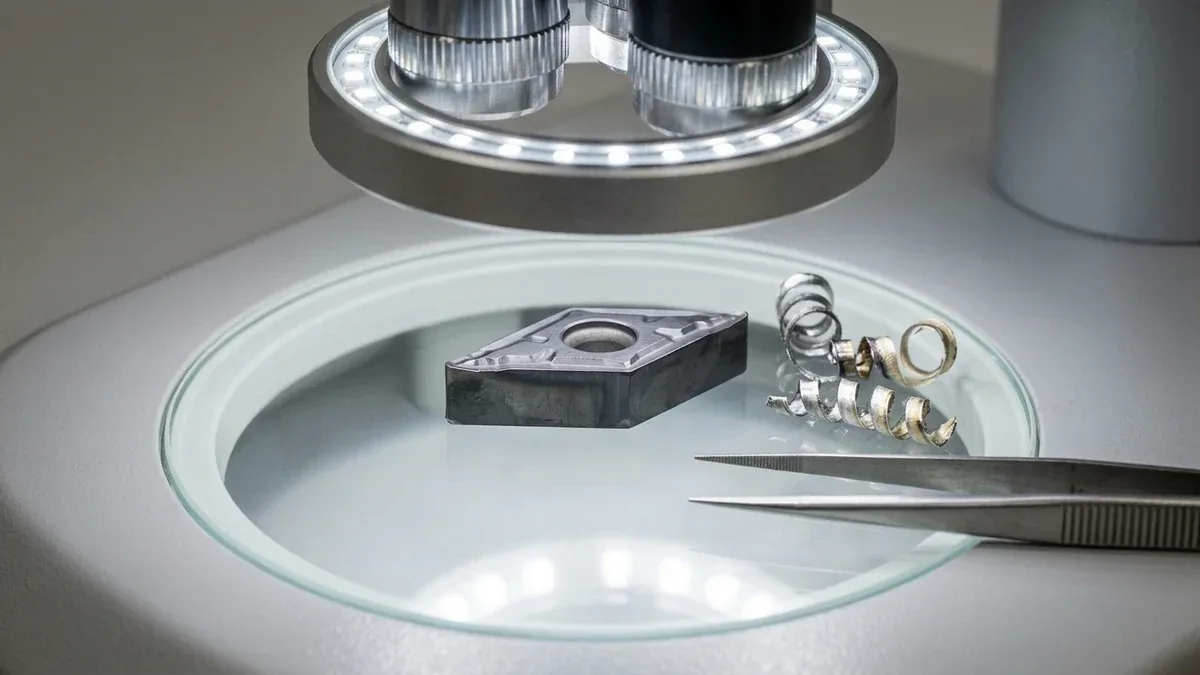
3. Thermal Partitioning and Taylor’s Tool Life Law in SFM
The ultimate physical ceiling on SFM is cutting zone temperature. During metal cutting, almost 98% of mechanical spindle power is transformed into intense localized heat within the primary and secondary shear zones.
1. The Thermal Partition Mechanism
In optimal cutting conditions, high cutting velocity creates a thermal gradient where 75% to 85% of generated heat is absorbed by the plastic deformation of the chip and immediately evacuated from the cutting zone. However, if SFM exceeds the thermal stability limit of the tool coating or carbide substrate:
- Tool interface temperatures soar past 950°C to 1200°C;
- Cobalt binder phase leaches out from tungsten carbide grains;
- Thermal diffusion and chemical crater wear accelerate rapidly, resulting in catastrophic edge collapse.
2. Taylor’s Empirical Tool Life Equation
The severe sensitivity of cutting tools to surface speed is expressed through the classical Taylor equation:
Where:
• T = Tool life in minutes until a defined flank wear threshold (VB = 0.3 mm)
• n = Taylor exponent (n ≈ 0.12 for HSS; n ≈ 0.25–0.35 for carbide; n ≈ 0.50+ for ceramics/cBN)
• C = Constant cutting speed yielding a 1-minute tool life
Because the exponent n for carbide is around 0.30, a modest 20% increase in SFM cuts tool life in half. Conversely, running significantly below the recommended SFM threshold causes severe adhesion, work hardening, and micro-chipping due to built-up edge formation.
4. Engineering Reference Matrix: Standard SFM Ranges by Material
The following engineering data table provides baseline SFM parameters, equivalent metric cutting speeds (Vc), and recommended tooling grades across key manufacturing materials:
| Workpiece Material | Material State | Roughing SFM (m/min) | Finishing SFM (m/min) | Recommended Tooling & Coating | Coolant Strategy |
|---|---|---|---|---|---|
| Aluminum 6061-T6 | Solution Treated & Aged | 800 – 1,800 (245–550) | 1,500 – 3,500 (455–1,065) | Uncoated / DLC Polished Micro-Grain Carbide | High-Pressure Flood (8–10% Emulsion) |
| Aluminum 7075-T6 | High-Strength Aerospace | 700 – 1,400 (215–425) | 1,200 – 2,600 (365–790) | ZrN / TiB2 Coated High-Rake Carbide | High-Volume Flood Coolant |
| Stainless Steel 304 / 316L | Austenitic (Work Hardens) | 250 – 450 (75–135) | 400 – 650 (120–200) | AlTiN / AlCrN PVD Coated Carbide | High-Pressure Flood (Prevent Thermal Shock) |
| Alloy Steel 4140 | Pre-Hardened (28–32 HRC) | 350 – 600 (105–180) | 550 – 850 (165–260) | TiCN / TiAlN Multi-Layer CVD/PVD | Dry with Air Blast (Carbide Milling); Flood (Turning) |
| Titanium Ti-6Al-4V | Grade 5 Annealed | 120 – 220 (35–67) | 200 – 320 (60–98) | TiAlSiN Nano-Composite Coated Carbide | High-Pressure Through-Tool (70+ Bar) |
| Inconel 718 | Precipitation Hardened | 60 – 120 (18–36) | 110 – 180 (33–55) | Sub-Micron Tough Carbide / SiAlON Ceramic | High-Pressure Flood (Carbide); Air Blast (Ceramics) |
| Brass C360 | Free-Cutting Brass | 600 – 1,200 (180–365) | 1,000 – 2,200 (305–670) | Uncoated Sharp Carbide / PCD | Dry or Light Mist Coolant |
| PEEK / POM-C (Delrin) | Engineering Polymers | 700 – 1,500 (215–455) | 1,200 – 2,500 (365–760) | Polished Razor-Sharp Uncoated Carbide | Compressed Cold Air Blast (Prevent Recasting) |
5. Engineering Case Study: Stepped Titanium Aerospace Sensor Housing
An aerospace instrumentation manufacturer contracted AS Prototypes to produce a precision Grade 5 titanium (Ti-6Al-4V) stepped pressure housing. The component featured three distinct turned outer diameters: Ø 3.000” (Ø 76.2 mm), Ø 1.750” (Ø 44.45 mm), and Ø 0.500” (Ø 12.7 mm), culminating in a precision seal face requiring Ra ≤ 0.4 μm and total runout under 0.010 mm.
- The Initial Legacy Failure: The client’s prior machine shop programmed the part using G97 fixed spindle speed at 750 RPM. On the Ø 3.000” OD, the effective surface speed was 589 SFM (179 m/min)—more than double titanium’s thermal threshold. Carbide inserts experienced catastrophic flank wear and thermal cracking after only 2 parts. Meanwhile, on the Ø 0.500” shoulder, SFM plummeted to 98 SFM, inducing severe built-up edge and tearing that resulted in a rough Ra = 1.8 μm surface finish.
- The AS Prototypes Solution:
- Migrated the program to G96 Constant Surface Speed calibrated precisely to 210 SFM (64 m/min) for roughing and 260 SFM (79 m/min) for finishing passes;
- Programmed a strict
G50 S2200spindle clamp to ensure machine dynamic stability; - Deployed micro-grain carbide turning inserts with nano-composite TiAlSiN PVD coating and integrated 70-bar through-tool high-pressure coolant directed straight into the tool-chip interface.
- The Production Results: Insert tool life expanded by 700% (from 2 parts to 16 parts per cutting edge). Surface roughness across all three stepped diameters and the critical seal face stabilized at an immaculate Ra = 0.28 μm, with total radial runout measuring within 0.008 mm.
6. Machinists’ Diagnostic Checklist: Diagnosing Surface Speed from Chips and Inserts
On the production floor, experienced CNC machinists monitor visual and acoustic cues to verify that SFM is operating within its optimal thermal window:
- Chip Color in Alloy Steels:
- Silvery-Grey Chips: SFM is too low. The tool is plowing rather than shearing, risking built-up edge and micro-chipping.
- Straw / Light Amber to Dark Blue Chips: Ideal SFM. Heat is properly partitioned into the chip and safely carried away.
- Dark Purple to Black Matte Chips: Excessive SFM. Extreme interface temperatures will cause rapid plastic deformation of the tool tip.
- Insert Wear Morphology:
- Flank Wear Land (VB): Gradual, uniform flank wear indicates well-balanced SFM. Rapid exponential flank wear within minutes indicates excessive SFM.
- Crater Wear: Deep dishing on the rake face signals extreme cutting temperatures, requiring an immediate 15% to 25% reduction in SFM.
- Built-Up Edge (BUE): Workpiece material welded onto the cutting edge indicates insufficient SFM. Increasing surface speed softens the shear zone and cleans the edge.
- Acoustic Feedback: A rhythmic, deep hum signals a healthy shear zone. A high-pitched, harmonic shriek indicates tool chatter or extreme thermal rubbing, requiring synchronization of SFM with feed rate per tooth (fz).
Shop-Floor Cost-Tolerance Trade-Offs & When NOT to Over-Specify
When releasing production drawings for high-speed CNC machined parts, applying blanket ±0.010 to ±0.020 mm (±0.0004″ to ±0.0008″) tolerances across non-mating clearance features increases machining cycle time by 2.0× to 3.5× without improving functional assembly. Our DFM engineers recommend specifying ISO 2768-mK on general structural walls while isolating tight GD&T callouts strictly to functional bearing bores, dowel pins, and sealing interfaces.
In our Shenzhen facility, prismatic 3-axis and 4-axis vertical machining centers (VMCs) with contoured soft jaws handle 80%+ of structural setups with maximum rigidity and cost efficiency, reserving simultaneous 5-axis contouring strictly for compound-angle ports and organic impellers. Each batch undergoes in-process gauge and 2.5D optical verification, with climate-controlled 20°C ± 1°C Zeiss CMM inspection available upon request prior to ex-factory release (4 to 8 business days for raw prototypes; 7 to 12 business days with MIL-A-8625 anodizing or ASTM A967 passivation).
🔗 Related CNC DFM & Metrology Engineering Guides:
To further optimize cycle time and dimensional stability in high-speed CNC machined parts, combine proper internal corner relief with datum-based coordinate inspection. Consult our shop-floor engineering guides on Maintaining Dimensional Stability in Thin-Wall Machining, Eliminating Sharp Internal Corners & Tool Deflection, and Precision CMM Metrology & GD&T Verification.
7. Technical Engineering FAQ
Surface Feet per Minute (SFM) measures the linear tangential velocity at the outer cutting edge of the tool or workpiece (expressed in m/min in metric systems), whereas Revolutions Per Minute (RPM) measures the rotational speed of the spindle shaft. Because tangential cutting speed depends on tool diameter, a small 3 mm end mill requires a much higher spindle RPM than a 50 mm face mill to maintain the same optimal SFM at the cutting edge.
According to Taylor's tool life equation (V · Tn = C), the empirical exponent n for carbide tooling typically lies between 0.25 and 0.30. Consequently, cutting edge temperature and flank wear scale exponentially with surface speed: a 20% increase in SFM can reduce carbide tool life by nearly 50%, whereas increasing chip load (feed per tooth) carries a much smaller thermal penalty.
In imperial units, spindle speed is calculated as RPM = (SFM × 12) / (π × D) ≈ (SFM × 3.8197) / D, where D is the cutter diameter in inches. In metric units using cutting speed Vc (m/min) and diameter D (mm), the formula is RPM = (Vc × 1000) / (π × D). If the calculated RPM exceeds the CNC spindle's maximum speed, the spindle is capped at 85%–90% of peak RPM and feed rate is scaled proportionally.
Running below the minimum SFM threshold reduces shear-zone temperature and causes workpiece material to pressure-weld onto the carbide cutting edge, forming a Built-Up Edge (BUE). On 6061-T6 aluminum, BUE tears the machined surface and clogs flutes; on work-hardening 316L stainless steel, excessive rubbing or dwelling without sufficient cutting velocity work-hardens the surface layer and triggers rapid notch wear.
Partner with Our Precision CNC Machining & Engineering Team
Eliminate tool deflection, residual stress distortion, and tolerance stack-up risks before production begins. Upload your 3D CAD files (STEP/IGES) and 2D GD&T drawings for a comprehensive shop-floor DFM review and custom quotation.
Upload 3D CAD for Engineering DFM & RFQ