In modern hardware product development, one of the most treacherous commercial milestones is transitioning from an engineering functional prototype to multi-cavity, high-volume mass production. This intermediate zone—often termed the “Hardware Valley of Death”—is where nascent hardware programs frequently collapse under the weight of unvalidated tooling investments, protracted steel mold lead times (12 to 16 weeks), unexpected assembly defects, and shifting customer demand.
To eliminate these catastrophic financial and schedule risks, forward-thinking original equipment manufacturers (OEMs) and agile hardware innovators deploy bridge production (also widely designated as bridge manufacturing, pilot run production, or low-volume manufacturing). Spanning batch sizes typically from 100 to 10,000 units, bridge production serves as the critical functional conduit linking Engineering Validation Testing (EVT) to full-scale Production Validation Testing (PVT) and mass rollout.
At AS Prototypes, we provide rapid tooling, multi-axis low-volume CNC batch machining, sheet metal fabrication, and polyurethane vacuum casting under one roof. This engineering guide details the core technologies of bridge manufacturing, financial break-even curves, regulatory compliance strategies, tooling material selection (P20 vs. 7075 Aluminum vs. S136), and practical Design for Manufacturability (DFM) rules to de-risk your next commercial hardware launch.
Executive Summary & Engineering Takeaways (BLUF)
- Strategic Volume Window: Bridge production spans the critical 100 to 10,000+ unit gap between initial EVT prototypes and high-cavitation mass production, de-risking market launches and supply-chain ramp-ups before locking capital into multi-cavity hardened steel molds.
- Core Bridge Technologies: Combines 7075-T651 aluminum or P20 pre-hardened steel rapid injection molds (1,000 to 50,000+ shots, 18 to 35 business days ex-factory turnaround), automated multi-axis CNC batch machining (50 to 1,000 units, 7 to 12 business days ex-factory), and polyurethane vacuum casting (20 to 250 units).
- Total Cost Crossover Math: Modular Master Unit Die (MUD) bridge inserts cut upfront tooling non-recurring engineering (NRE) by 60% to 80% compared to multi-cavity H13/S136 production molds while reducing per-part price by up to 85% compared to direct CNC machining at 2,500-unit volumes.
- Steel-Safe Iteration Agility: Designing bridge mold cores and cavities in steel-safe direction allows rapid CNC or EDM modification of snap-fit hooks, bosses, and wall ribs between DVT and PVT builds without scrapping the mold base.
Article Engineering Navigation
- 1. What is Bridge Production? Strategic Architecture
- 2. Core Manufacturing Technologies for Bridge Production
- 3. Engineering Comparison: Prototyping vs. Bridge Production vs. Mass Production
- 4. Financial Economics: The Break-Even Analysis of Bridge Tooling
- 5. Quality Assurance & Metrology in Bridge Manufacturing
- 6. Design for Manufacturability (DFM) Rules for Bridge Tooling
- 7. Technical Engineering FAQ
1. What is Bridge Production? Strategic Architecture
Bridge production is a specialized, agile manufacturing methodology executed during the transition phase between initial functional prototype validation and high-volume mass production. Rather than waiting 3 to 4 months for expensive, hardened multi-cavity production tooling to be cut in tool steels like H13 or S136, bridge manufacturing leverages flexible, fast-turnaround production technologies to output real, end-use production-grade parts in days or weeks.
Core Strategic Objectives of Bridge Manufacturing:
- Accelerate Time-to-Market (First-Mover Advantage): Delivering products to early adopters, enterprise pilot customers, or Kickstarter backers 12 to 16 weeks ahead of mass production schedules, capturing critical market share and early revenue.
- De-Risk Capital Investment: Committing substantial capital expenditure to high-cavitation hardened steel molds before real-world field validation is reckless. Bridge tooling allows engineering teams to identify thermal shrinkage, warpage, gate blush, or assembly interferences on low-cost tooling before hard steel is cut.
- Regulatory documentation & Clinical Trials: Regulatory agencies (FDA for Class II/III medical devices, FAA/EASA for aerospace, CE, and UL) require parts manufactured via the actual intended production process using production-grade resins or alloys for bio-compatibility testing, mechanical endurance trials, and electromagnetic compliance (EMC).
- Supply Chain Buffer & Surge Demand: If primary mass production tooling suffers downtime, maintenance overhauls, or unexpected shipping bottlenecks, bridge tooling serves as an active secondary production buffer preventing supply chain line-down penalties.
2. Core Manufacturing Technologies for Bridge Production
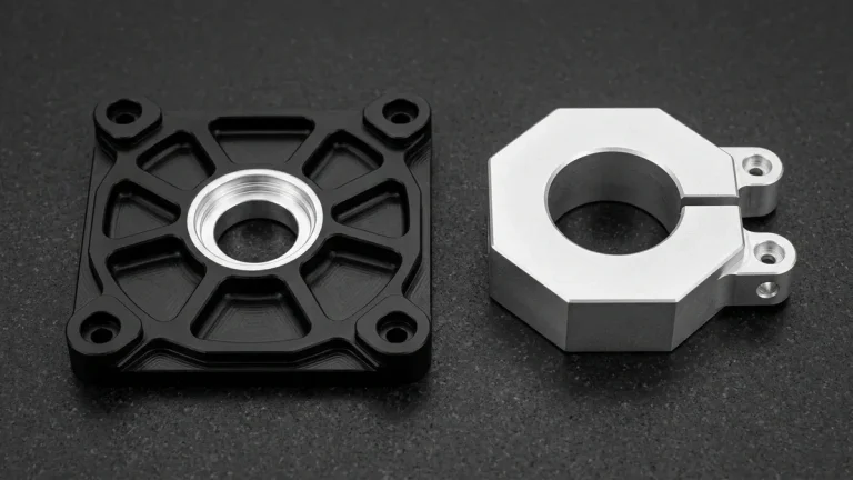
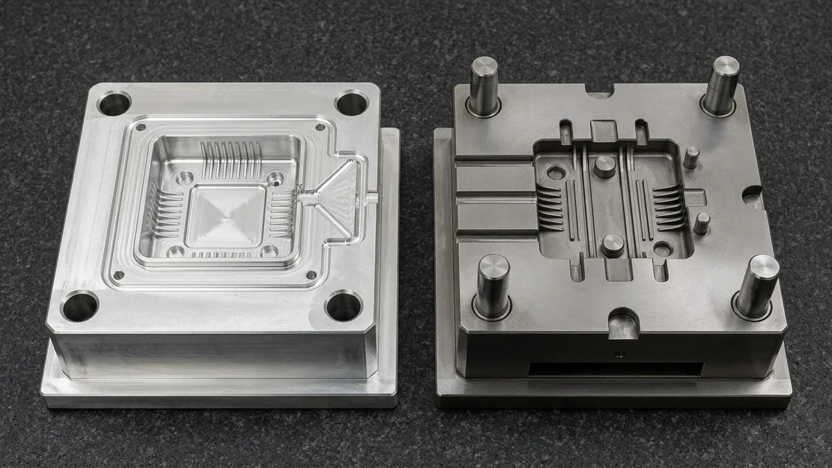
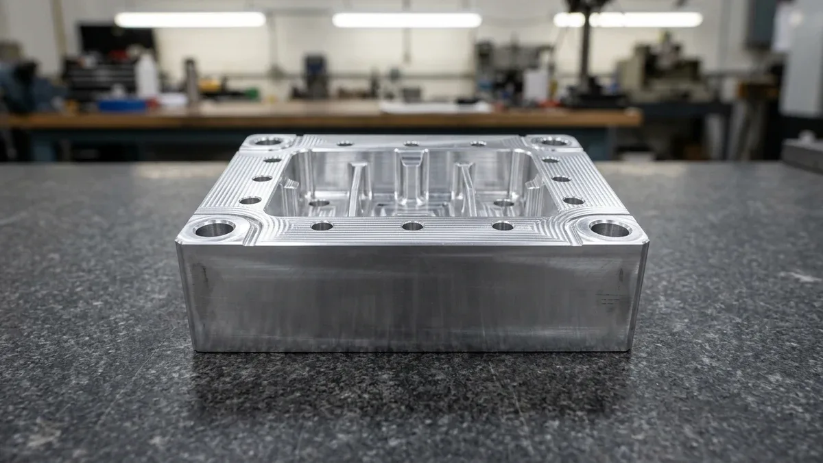
As shown in Figure 1, high-speed 3-axis CNC milling of 7075-T651 wrought aluminum plate stock produces a rapid bridge-tooling mold core insert complete with drafted cavity ribs, reamed ejector-pin holes, and precision leader-pin bores. Aluminum inserts dissipate melt heat rapidly while cutting tooling lead times to just a few weeks.
Bridge manufacturing is not a single process; rather, it is a tailored portfolio of rapid manufacturing technologies selected based on part geometry, material specifications, and batch volume requirements:
1. Rapid Tooling & Bridge Injection Molding
Rapid tooling utilizes standardized Master Unit Die (MUD) bases fitted with custom CNC-machined core and cavity inserts. Instead of machining an entire mold base from scratch, toolmakers machine only the proprietary cavity inserts from pre-hardened tool steel (P20, NAK80) or high-strength aircraft aluminum (Alloy 7075-T6 or Alumec 89).
- Tooling Lead Time: Slashed from 10–14 weeks down to 18 to 35 business days.
- Tooling Life: Aluminum tooling delivers 1,000 to 10,000 shots; P20 pre-hardened steel tooling reliably shoots 20,000 to 50,000 parts.
- Production Resin Compatibility: Can inject true commercial engineering resins, including glass-filled nylon (PA66-GF30), polycarbonate (PC), PBT, medical-grade polypropylene (PP), and high-temp PEEK.
2. Low-Volume CNC Batch Machining
When parts have complex structural geometries, tight linear tolerances (± 0.01 mm), or require aerospace-grade alloys (6061-T6, 7075-T7351, 316L Stainless, Titanium Ti-6Al-4V), low-volume CNC machining is the ultimate zero-tooling bridge solution.
- Zero Tooling CapEx: Immediate production start directly from 3D CAD models using modular vacuum chucks, multi-part tombstones on 4-axis/5-axis machining centers, and automated pallet changers.
- Batch Sweet Spot: Highly cost-effective for runs of 50 to 2,000 units, delivering identical mechanical integrity to mass production forgings and billets.
3. Polyurethane Vacuum Casting (Silicone Tooling)
Utilizing high-accuracy SLA 3D printed master patterns, liquid silicone rubber is poured under vacuum to create flexible silicone molds. These molds are subsequently injected with multi-component polyurethane resins formulated to replicate ABS, PP, POM, and soft elastomeric rubbers (Shore 30A to 90A).
- Turnaround: 7 to 10 business days for the first batch.
- Volume Range: 20 to 50 parts per silicone mold before thermal mold degradation occurs. Ideal for clinical trial hospital enclosures, trade-show demo models, and functional ergonomic testing.
4. Rapid Sheet Metal Fabrication & Stamping
Before committing to expensive progressive hard stamping dies, bridge sheet metal utilizes high-power fiber laser cutting, CNC turret punching, and precision press brake bending with modular stage tooling. It accommodates batches from 100 to 5,000 chassis, server brackets, and EMI shielding enclosures.
3. Engineering Comparison: Prototyping vs. Bridge Production vs. Mass Production
The following engineering matrix outlines the technical, operational, and financial divergence between the three foundational phases of product manufacturing:
| Manufacturing Dimension | Functional Prototyping (EVT) | Bridge Production (DVT / Pilot) | High-Volume Mass Production (PVT) |
|---|---|---|---|
| Typical Batch Volume | 1 to 50 units | 100 to 10,000 units | 10,000 to 1,000,000+ units |
| Dominant Technologies | SLA/SLS 3D Printing, CNC Prototyping, Vacuum Casting | Rapid Tooling (MUD), Batch CNC, Metal 3D Printing (DMLS) | Hardened Multi-Cavity Steel Molds, Progressive Stamping, Die Casting |
| Tooling Material & Cost | None or Soft Silicone Molds (Minimal Tooling NRE) | 7075-T6 Aluminum, P20, NAK80 (Low-to-Moderate Bridge Tooling NRE) | Hardened H13, S136, DIN 1.2344 (High Multi-Cavity Production Tooling CapEx) |
| Lead Time to First Part | 4 to 8 business days | 18 to 35 business days | 12 to 16 weeks |
| Piece-Part Unit Cost | High (no tooling amortization) | Moderate (competitive amortized cost) | Lowest (maximum economies of scale) |
| Engineering Flexibility | Infinite (CAD changes applied instantly per part) | Moderate-High (inserts easily re-cut via CNC/EDM) | Extremely Rigid (tool modifications cost weeks & thousands) |
| Primary Objective | Proof-of-Concept, form fit, basic functional testing | Pilot launch, regulatory trials, DFM tooling proof, market test | Global distribution, maximum margin, automated production |
4. Financial Economics: The Break-Even Analysis of Bridge Tooling
The total cost of ownership (TCO) in manufacturing is governed by the classic economic formula:
Consider an injection-molded medical device chassis requiring 2,500 units for clinical trials and early regional commercial rollout:
- Scenario A: Low-Volume CNC Machining Entire Batch:
- Tooling CapEx: Zero Dedicated Tooling (Direct CAD Setup)
- Relative Piece-Part Cost: 1.00× Baseline CNC Unit Index
- Total Program Cost at 2,500 Units: High Unamortized Machine-Hour Expenditure (1.00× Baseline)
- Scenario B: Rapid Tooling (P20 Steel Bridge Mold):
- Tooling CapEx: Low Modular MUD Aluminum/P20 Insert Investment
- Relative Piece-Part Cost: ~0.07× CNC Unit Index (injected in medical-grade ABS/PC)
- Total Investment for 2,500 units: Moderate Bridge Tooling NRE + (2,500 units × Low Molded Unit Rate) = 87% Total Program Cost Reduction vs. Direct Machining
- Net Program Savings vs. Direct CNC: Approximately 87% Total Cost Reduction at 2,500 Units
- Scenario C: High-Volume Production Hard Tooling:
- Tooling CapEx: High 8-Cavity Hardened S136 Hot-Runner Mold Investment
- Relative Piece-Part Cost: ~0.02× CNC Unit Index
- Total Investment for 2,500 units: High Multi-Cavity Steel Tooling NRE + (2,500 units × Ultra-Low Unit Rate) = Unamortized Tooling Overhead at Bridge Volumes
- Result: Far more expensive than bridge tooling at this volume, while tying up capital for 14 weeks!
The Break-Even Sweet Spot: For volumes between 250 and 15,000 parts, rapid bridge tooling delivers the absolute lowest total program cost, superior lead time, and uncompromised production-grade material properties.
5. Quality Assurance & Metrology in Bridge Manufacturing
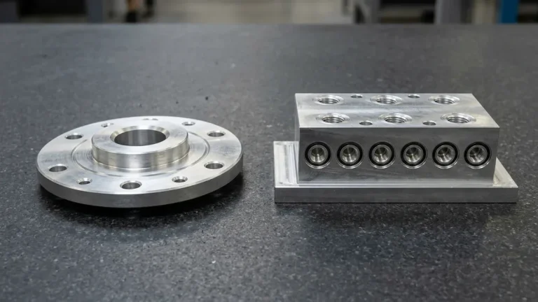
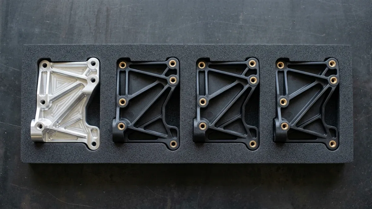
Figure 2 illustrates the seamless bridge production transition by comparing a CNC-machined 6061-T6 aluminum validation bracket directly against three identical glass-filled nylon bridge-molded brackets with heat-staked brass inserts. Validating fit and kinematics on a machined unit before cutting rapid tooling eliminates costly mold rework during pilot scaling.
A common misconception is that because bridge production involves low volumes, quality standards can be relaxed. In truth, bridge production is the exact phase where statistical quality control (SQC) must be rigorously established before scaling:
1. First Article Inspection (FAI) per First Article Inspection (FAI) & Dimensional Metrology Standards
Every newly cut bridge mold produces initial samples (T1 trials) that undergo 100% ballooned-print inspection. In our inspection lab, a programmable coordinate measuring machine (CMM) verifies true position, planar flatness, concentricity, and critical dimensions against 2D technical drawings, providing verified FAI inspection packages.
2. Process Capability Analysis (Cpk and Ppk)
During pilot runs of 500 to 1,000 units, dimensional data on critical-to-quality (CTQ) features is collected to compute process capability indices:
Achieving a Cpk ≥ 1.33 verifies that the injection molding cycle parameters (melt temperature, pack pressure, hold time, cooling rate) are statistically capable of producing zero-defect parts consistently.
3. Moldflow Simulation & Thermal Warpage Verification
Prior to cutting mold steel, AS Prototypes engineers execute comprehensive Autodesk Moldflow simulations to optimize gate placement, identify weld line locations, predict volumetric shrinkage, and eliminate differential cooling warpage.
6. Design for Manufacturability (DFM) Rules for Bridge Tooling
Adhering to these practical DFM guidelines ensures your bridge tooling inserts are manufactured rapidly and operate without part ejection failures:
1. Design Adequate Draft Angles (1.0° – 2.0°)
Zero-draft vertical ribs cause parts to drag, scuff, and stick inside the mold cavity. Provide a minimum of 1.0° draft per side on untextured vertical walls; for heavy EDM textured surfaces (VDI 27–33), increase draft to 3.0° – 5.0°.
2. Maintain Uniform Nominal Wall Thickness
Thick wall intersections freeze slower than adjacent thin ribs, creating localized volumetric contraction that pulls exterior surfaces inward, resulting in unsightly sink marks and internal thermal voids. Core out thick bosses and maintain nominal wall thickness within ± 15%.
3. Maximize Steel-Safe Dimensions
When designing critical press-fit bearing bores or snap-fit cantilever latches, design them “steel-safe” (undersized on external surfaces and oversized on internal mold cores). Adding material to a plastic part requires removing steel from the mold via high-speed CNC milling or EDM—a fast, low-cost modification. Subtracting material from plastic requires welding metal back onto mold inserts, which is difficult and expensive.
4. Leverage Hand-Load Loose Inserts for Complex Undercuts
In high-volume mass tooling, external side undercuts necessitate complex, hydraulic slide actions and mechanical lifters that inflate mold costs by thousands of dollars. In rapid bridge tooling, toolmakers frequently utilize manual hand-load inserts that eject with the molded part and are re-inserted into the mold cavity by the press operator or robotic picker each cycle. This simple DFM strategy saves up to 40% in upfront mold tooling capital.
🔗 Related Rapid Tooling & Low-Volume Manufacturing Guides
7. Technical Engineering FAQ
Transition to rapid bridge tooling during late EVT or early DVT once 85%–90% of part geometry is frozen and volume exceeds 250–500 units. Bridge molds deliver production thermoplastics like PC, ABS, and PA66-GF30 required for drop testing, UL 94 flammability, and ingress protection validation.
Modular Master Unit Die (MUD) inserts machined from 7075-T651 aluminum or pre-hardened P20 steel (28–40 HRC) allow direct CNC rework without annealing cycles. When features are designed steel-safe, our toolmakers mill deeper ribs, enlarge bosses, or swap sub-inserts within 4–8 business days.
High-strength 7075-T651 aluminum bridge molds reliably sustain 1,000–10,000 shots using unfilled resins like ABS, PP, PC, or TPE. For abrasive glass-filled polymers like PA66-GF30 or runs of 10,000–50,000 shots, specify P20 or NAK80 steel inserts to prevent gate erosion and parting-line flash.
Direct CNC machining delivers initial bridge batches in 4–8 business days ex-factory with zero tooling setup delay, scaling to 7–12 business days for 50–500 units. Rapid aluminum and P20 steel bridge molds require 18–35 business days ex-factory for cavity machining, EDM finishing, and T1 sample validation.
Ready to Validate Your CAD Design for Precision Manufacturing?
Upload your 3D CAD models (STEP, IGES, SolidWorks) and 2D engineering drawings for a comprehensive DFM engineering review and custom quotation from our in-house CNC machining and prototyping team.
Request a Custom DFM Review & Quote →