In mechanical design, powertrain engineering, and high-precision CNC manufacturing, few components are as foundational yet demanding as the mechanical shaft. Whether driving the transmission of an electric vehicle, rotating the cutter head of a 5-axis CNC machining center at 24,000 RPM, or synchronizing the valves of an internal combustion engine, shafts are the primary physical conduit for transmitting torque, angular velocity, and rotational power across mechanical assemblies.
However, asking what is a shaft reveals an engineering domain far more intricate than simple cylindrical round stock. A rotating shaft is subject to complex, simultaneous dynamic stress states: torsional shear from transmitted power, cyclic reversed bending from mounted gears and pulleys, axial thrust loads from helical gear teeth, and high-frequency vibrational resonance. Designing a reliable shaft demands rigorous stress analysis per ASME codes, rotordynamic critical whirling speed calculations, precision material selection, and micro-inch surface finishing.
At AS Prototypes, our CNC turning centers, multi-tasking mill-turn lathes, and Swiss screw machines manufacture mission-critical transmission shafts, precision spindle arbors, and splined drive shafts held to ±0.005 mm tolerances. This comprehensive engineering guide examines the functional taxonomy of mechanical shafts, solid vs. hollow efficiency mechanics, ASME shaft sizing equations, fatigue notch mitigation, and precision CNC manufacturing protocols.
Executive Summary & Engineering Takeaways (BLUF)
- Core Mechanical Definition: A shaft is a rotating cylindrical machine element engineered to transmit power, rotational speed, and torque between coupled gears, pulleys, sprockets, and motor rotors while withstanding combined cyclic bending moments and torsional shear.
- Hollow vs. Solid Inertia Efficiency: Because polar moment of inertia scales with the fourth power of diameter (J = π·d4 / 32), boring out the central 50% core of a solid shaft (di = 0.5·do) removes 25% of its dead weight (mass) while retaining 93.75% of its torsional stiffness and polar section modulus.
- Metallurgy & Surface Hardening: Precision shafts utilize 4140/4340 alloy steels (28–34 HRC core), 17-4PH precipitation-hardening stainless steel (Condition H900, 40–44 HRC), or case-carburized 8620/20CrMnTi steel achieving 58–62 HRC wear-resistant bearing journals over a ductile core.
- Coaxiality & Grinding Precision: Single-setup mill-turn machining paired with post-heat-treatment cylindrical grinding holds ISO h5/h6, g6, k6, and p6 bearing journal tolerances within ±0.005 mm (±0.0002″), total indicator reading (TIR) runout ≤0.010 mm (0.0004″), and Ra 0.2–0.4 μm (8–16 μin) seal finishes.
Article Engineering Navigation
- 1. What is a Shaft? Fundamentals & Definitions
- 2. Taxonomy of Mechanical Shafts & Functional Configurations
- 3. Shaft Design Equations: ASME Code & Stress Formulations
- 4. Engineering Comparison: Shaft Classifications & Operating Environments
- 5. Quality Assurance, Metrology & Dynamic Balancing
- 6. Design for Manufacturability (DFM) Rules for Custom Shafts
- 7. Technical Engineering FAQ
1. What is a Shaft? Fundamentals & Definitions
In mechanical engineering, a shaft is defined as a rotating machine element—predominantly circular or annular in cross-section—specifically engineered to transmit torque and mechanical power from an input driving source (such as an electric motor, turbine, or engine) to an output driven machine element (such as gears, pulleys, sprockets, or impellers).
Distinguishing Shafts from Axles and Spindles
In engineering terminology, three rotating components are frequently confused:
- Shaft: Transmits mechanical power and torque while rotating. It is simultaneously subjected to torsion (twisting moments) and transverse bending loads (e.g., motor shafts, automotive driveshafts, pump shafts).
- Axle: A non-torque-transmitting structural member. An axle supports rotating wheels, idler pulleys, or hoisting drums. It may remain stationary while wheels rotate on bearings around it (like a non-driven trailer axle), or rotate with the wheels, but it experiences bending moments only with negligible torsional loading.
- Spindle: A short, highly rigid shaft that carries a cutting tool (e.g., a milling machine or router spindle) or a workpiece holding device (e.g., a lathe spindle). Spindles prioritize ultra-low radial and axial runout (±0.005 mm), extreme dynamic stiffness, and thermal stability over long-distance power transmission.
2. Taxonomy of Mechanical Shafts & Functional Configurations
Depending on spatial packaging, mechanical constraints, and kinematic motion requirements, mechanical shafts are categorized into specialized architectures:
1. Transmission Shafts (Drive Shafts & Jackshafts)
Positioned between the prime mover and the working mechanism, transmission shafts convey power across distances. They feature stepped diameters, bearing journals, and keyways or involute splines (per ANSI B92.1 or DIN 5480) to mount stepped gearing, clutches, and universal joints.
2. Machine Shafts (Crankshafts & Camshafts)
Integral to specific machine kinematics. A crankshaft converts reciprocating linear piston motion into continuous rotational torque via offset crankpins and counterweights. A camshaft utilizes eccentric egg-shaped lobes to actuate intake and exhaust poppet valves in precise timing with engine rotation.
3. Solid vs. Hollow Shafts: The Mechanics of Rotational Inertia
In high-performance aerospace, racing, and marine applications, hollow shafts are widely specified over solid shafts. The underlying mechanics are governed by the distribution of shear stress across the circular cross-section:
Torsional shear stress (τ) is zero at the central neutral axis and scales linearly to its maximum magnitude (τmax) at the outermost fiber (r = D/2). The material near the core contributes almost nothing to torsional resistance while adding dead weight. By boring out the inner 50% diameter of a solid shaft (di = 0.5 Do):
- Mass Reduction: The shaft sheds 25% of its total weight.
- Torsional Strength Retained: The polar section modulus (Zp) drops by less than 6.25%.
- Critical Speed Elevation: Removing core mass raises the shaft’s natural frequency, allowing higher rotational operating speeds before encountering resonant whirling.
3. Shaft Design Equations: ASME Code & Stress Formulations
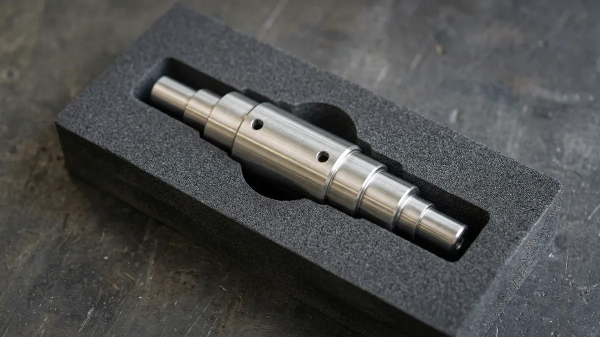
To minimize rotational inertia without sacrificing torsional stiffness, Figure 1 highlights a CNC-turned 17-4PH stainless steel hollow rotor shaft featuring a concentric deep-bored internal cavity and cross-drilled radial lubrication ports. Precision gun-drilling followed by finish boring maintains uniform wall thickness and dynamic balance at high operating speeds.
Engineering a shaft requires calculating the minimum safe shaft diameter (d) to survive combined static and cyclic reversed loading without yielding or fatigue fracture.
1. The ASME Shaft Design Equation
The standard ASME code equation for commercial transmission shafting subjected to combined torsional moment (T) and bending moment (M) derives from the Maximum Shear Stress Theory (Tresca) incorporating dynamic shock and fatigue factors:
Where:
- d = Required shaft solid diameter (mm)
- M = Maximum resultant bending moment (N· mm), combining vertical and horizontal bending components: M = √(Mv2 + Mh2)
- T = Transmitted torsional moment (N· mm): T = (9.55 × 10⁶ · P (kW)) / (N (RPM))
- τallow = Allowable shear stress of the shaft material (MPa), typically taken as min(0.30 Sy, 0.18 Sut) for commercial steel without keyways, reduced by 25% if keyways are present.
- Kb = Combined shock and fatigue factor applied to bending (1.5 – 2.0 for rotating shafts with minor to heavy shock).
- Kt = Combined shock and fatigue factor applied to torsion (1.0 – 1.5).
2. Torsional Rigidity (Angular Twist Limitation)
In precision machine tool drives, gearboxes, and optical scanners, dynamic stiffness outweighs pure yield strength. Excessive torsional twist causes gear tooth misalignment, backlash, and timing errors. The angle of twist (θ) is calculated as:
Where L is the shaft length, J = (π d4) / (32) is the polar moment of inertia, and G is the shear modulus of elasticity (≈ 79.3 GPa for alloy steel). Industry standards restrict angular deflection to ≤ 0.25° – 1.0° per meter of length.
3. Critical Whirling Speed (Rayleigh-Ritz Method)
When a shaft rotates, slight residual center-of-mass eccentricity causes centrifugal forces to bow the shaft outward. At the critical whirling speed (ωc), rotational frequency matches the shaft’s natural bending vibration frequency, causing violent, catastrophic whipping resonance. For a stepped shaft supporting multiple masses:
Operational shaft speeds must be designed to run either comfortably below 80% of ωc (rigid shaft design) or safely above 120% of ωc (supercritical flexible shaft design).
4. Engineering Comparison: Shaft Classifications & Operating Environments
The following engineering reference matrix details the primary classifications of mechanical shafts, their dynamic loading conditions, typical materials, and finishing standards:
| Shaft Category | Primary Dynamic Loads | Typical Materials | Heat Treatment & Surface Finish | Key Design Features | Representative Applications |
|---|---|---|---|---|---|
| Precision Spindle Shaft | High RPM, radial cutting forces, axial preload | AISI 4340, 8620, Nitralloy 135M | Case Carburized / Gas Nitrided, Ra ≤ 0.2 μm (8 μin) | Internal cooling channels, precision bearing journals (h5/p6), HSK/CAT tool tapers. | CNC machine tool spindles, dental drill rotors, grinding heads. |
| Automotive Drive Axle / Half-Shaft | High reversing torque, shock impact, vehicle weight | AISI 4140, 4340, 300M Alloy Steel | Through-hardened & tempered (32–36 HRC), shot-peened | Rolled involute splines, constant velocity (CV) joint bell housings. | EV differential drive shafts, heavy truck axles, racing prop shafts. |
| Gearbox Transmission Shaft | Continuous torsional torque, gear separation bending | AISI 1045, 4140, 20CrMnTi | Induction Hardened journals (56–60 HRC (620–700 HV)), ground seats | Stepped shoulders with DIN 509 relief grooves, multiple keyways, circlip grooves. | Industrial speed reducers, robotic actuator gearboxes, wind turbines. |
| Marine Propeller Shaft | Continuous high torque, heavy axial thrust, seawater corrosion | Aquamet 17/22, 17-4PH, 316L, Monel K-500 | Solution Annealed & Aged (H1150), polished seal sleeves | Extreme length-to-diameter ratio (L/D > 20), tapered propeller fit with keyway. | Commercial vessels, naval patrol boats, offshore waterjet propulsion. |
| Engine Crankshaft | Severe cyclic bending and twisting shock pulses | Forged 4340 Steel, Spheroidal Nodular Cast Iron | Deep Fillet Induction Hardened, micro-polished journals | Cross-drilled pressurized oil passages, counterweights, heavy fillet radii. | High-performance internal combustion engines, reciprocating compressors. |
5. Quality Assurance, Metrology & Dynamic Balancing
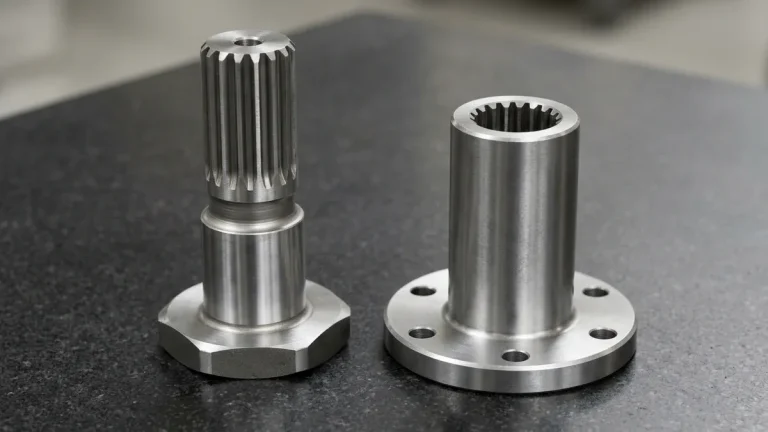
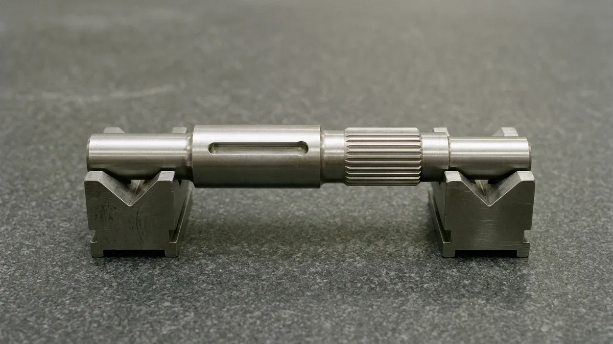
As demonstrated in the 4140 alloy steel stepped power-transmission drive shaft supported horizontally across matched steel V-blocks in Figure 2, high-torque rotary joints pair a milled closed-end round-ended parallel keyway slot on the central bearing journal with longitudinal external involute splines and filleted DIN 509 shoulder relief undercut grooves to minimize torsional shear stress concentration.
In high-speed rotating machinery, an otherwise dimensionally perfect shaft will destroy bearing assemblies within hours if geometric runout or dynamic unbalance is overlooked:
1. Dynamic Balancing per ISO 1940-1
As a shaft spins, any asymmetric mass distribution (m) at radius (r) produces rotating centrifugal unbalance force: F = m · r · ω2. At 10,000 RPM, an unbalance of 10 grams at a 50 mm radius generates 548 Newtons (123 lbf) of destructive rotating radial force (54.8 N per gram). AS Prototypes operates computerized horizontal dynamic balancing systems:
- Grade G2.5: Standard for automotive drive shafts, electric motor rotors, and pump impellers.
- Grade G1.0 / G0.4: Ultra-precision balancing for high-speed CNC milling spindles, turbine rotors, and gyroscopes.
2. Geometric Form Tolerancing (GD&T)
- Total Radial Runout (Circular Runout ≤ 0.005 mm): Verified by mounting the shaft between precision dead centers while sensitive lever-type dial test indicators measure radial deviation across multiple axial positions as the shaft completes full revolutions.
- Cylindricity and Coaxiality: Verified on coordinate measuring machines (CMM) and optical roundness testers to ensure all stepped journals share a common datum axis.
6. Design for Manufacturability (DFM) Rules for Custom Shafts
Adhering to these practical DFM guidelines during CAD development drastically reduces machining cycle times and prevents premature shaft failure:
1. Avoid Sharp Inside Shoulders (Eliminate Fatigue Notches)
Never specify a razor-sharp 90° inside corner at step diameter transitions. Sharp corners create catastrophic stress concentration factors (Kt > 3.0). Always incorporate a transition fillet radius of at least r ≥ 0.1 · d or design a standardized DIN 509 Form E / Form F undercut for bearing clearance.
2. Standardize Keyways & Splines
Where multiple keyways exist on a single shaft, design them with identical slot widths and depths located on the same angular clocking position. This allows all keyways to be cut in a single setup without rotary indexing.
3. Account for Length-to-Diameter Ratios (L/D)
Turning long, slender shafts where L/D > 4 causes intense cutting deflection and chatter under tool radial forces. For shafts exceeding L/D = 4, engineers must allow for a centered tailstock live center drill point; for L/D > 8, design clearance zones for steady rests or follow rests.
4. Sequence Diameters Progressively
Design stepped shafts with diameters that decrease monotonically from the center toward the shaft ends. This enables continuous single-setup turning and simplifies grinding wheel clearances.
🔗 Related CNC Turning, Grinding & Fit Tolerance Guides
7. Technical Engineering FAQ
A rotating shaft transmits dynamic torque under combined bending and torsional shear, whereas an axle supports radial loads with zero torque transmission. A spindle is a short, high-rigidity shaft engineered to maintain ≤0.005 mm dynamic runout on precision machine tool axes.
Induction hardening or carburizing steel shafts to 55–62 HRC induces 0.05–0.15 mm of thermal bow that exceeds standard CNC turning accuracy. Cylindrical grinding between dead centers removes this distortion, restoring ±0.005 mm (ISO h6) bearing journals and Ra 0.2 µm lip-seal surfaces.
A single DIN 6885 parallel keyway concentrates torsional shear into one notch, cutting shaft fatigue strength by 30%–50%. Specify DIN 5480 or ANSI B92.1 involute splines to distribute load across 12–36 teeth, boosting torque capacity by 300% and enabling smooth axial sliding.
Re-chucking a stepped shaft in a 3-jaw chuck introduces 0.020–0.050 mm of coaxiality error between bearing journals. We eliminate datum shift by machining all steps and milled features in one setup on mill-turn centers, or grinding between 60° DIN 332 centers.
Ready to Validate Your CAD Design for Precision Manufacturing?
Upload your 3D CAD models (STEP, IGES, SolidWorks) and 2D engineering drawings for a comprehensive DFM engineering review and custom quotation from our in-house CNC machining and prototyping team.
Request a Custom DFM Review & Quote →