Mastering material hardness testing is essential for hardware teams balancing tight dimensional tolerances, surface integrity, and scalable production economics. In mechanical engineering and precision manufacturing, material hardness is one of the most critical metallurgical parameters governing wear resistance, fatigue life, structural integrity, and machinability. Whether fabricating a high-speed transmission shaft, an aerospace landing gear bushing, or a high-pressure injection mold cavity, designing with the incorrect hardness specification inevitably triggers catastrophic premature failure—either through rapid adhesive wear and galling if the core is too soft, or brittle catastrophic cracking if the structure is excessively hard and under-tempered.
For machine shops and product developers, material hardness directly dictates cutting tool selection, feed and speed parameters, toolpath strategies, and the sequencing of thermal treatments. In this comprehensive guide, our manufacturing engineers break down the fundamental physics of hardness, compare the major indentation test scales (Rockwell, Vickers, Brinell, and Shore), examine microhardness case-depth profiling, and explore manufacturing techniques for machining ultra-hard alloys.
By AS Prototypes Engineering Team — Senior Metallurgy & Precision Grinding Specialist (12+ Years Shop-Floor Experience) | Last Updated: October 2026
Executive Summary & Engineering Takeaways (BLUF)
- Four Standardized Indentation Scales: Industrial quality assurance relies on Rockwell (ASTM E18, depth differential under preload/major load), Vickers (ASTM E384, optical diagonal measurement of a 136° diamond pyramid), Brinell (ASTM E10, 10 mm tungsten carbide ball for coarse castings), and Shore Durometer (ASTM D2240 for elastomers/polymers).
- Tensile Strength Correlation: For carbon and low-alloy steels between 200 and 500 HBW, ultimate tensile strength (UTS) approximates UTS (MPa) ≈ 3.45 × HBW (or UTS in psi ≈ 500 × HBW), enabling rapid non-destructive verification of heat-treatment batch integrity.
- Minimum Thickness & Edge Spacing Rule: Accurate hardness testing requires specimen thickness to be at least 10× the indenter penetration depth (and spacing ≥3× indentation diameter from part edges) to prevent anvil effect false readings and edge bulging.
- Hard Machining & Grinding Thresholds: Conventional solid carbide milling handles alloys up to 42–45 HRC; components heat-treated to 50–62 HRC (H13, S136, D2, 440C, case-hardened 4140) require pre-hardening roughing followed by PCBN hard turning, Wire EDM, or CNC surface/cylindrical grinding to ±0.005 mm (±0.0002″).
Article Engineering Navigation
- 1. What is Material Hardness? Engineering Definitions and Mechanisms
- 2. The Major Indentation Hardness Testing Methods
- 3. Engineering Hardness Testing Methods & Material Selection Table
- 4. Hardness vs. Hardenability: Key Distinctions in Heat Treatment
- 5. Manufacturing Strategies for Machining Hard Materials
- 6. Technical Engineering FAQ
1. What is Material Hardness? Engineering Definitions and Mechanisms
At an atomic and metallurgical level, hardness is defined as a material’s capacity to resist localized permanent plastic deformation, scratching, abrasion, or penetration under a concentrated external load. While frequently conflated in informal discussions with tensile strength or toughness, hardness reflects localized surface yielding rather than bulk energy absorption:
- Hardness vs. Tensile Strength: For carbon and low-alloy steels, hardness exhibits a strong direct correlation with ultimate tensile strength (UTS). A standard empirical rule of thumb states that UTS (in MPa) is approximately equal to 3.45 × HBW. However, hardness measures resistance to surface penetration, whereas tensile strength measures resistance to global elongation and necking under axial tension.
- Hardness vs. Toughness: Hardness and fracture toughness typically sit on opposite ends of a mechanical trade-off. Increasing hardness through quenching or work hardening restricts dislocation mobility within the crystal lattice, which simultaneously decreases ductility and impact energy absorption (Charpy V-notch impact energy).
- Scratch Hardness vs. Indentation Hardness vs. Dynamic Rebound: While mineralogists rely on the qualitative 10-point Mohs scratch scale, precision manufacturing almost universally specifies indentation hardness (penetrating a standardized diamond or tungsten carbide indenter into the specimen under calibrated loads) or dynamic rebound hardness (Leeb rebound testing for large forgings and cast press frames).
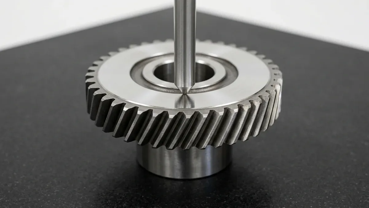
In Figure 1, a 120-degree conical diamond Brale indenter presses vertically onto the flat surface-ground rim of a case-hardened 4140 alloy steel spur gear supported on a cylindrical steel anvil per ASTM E18 Rockwell C testing. Testing on a flat, scale-free ground land prevents curvature-induced reading errors.
2. The Major Indentation Hardness Testing Methods
Each hardness test method relies on distinct indenter geometries, load ranges, and optical or depth-sensing measurement systems. Selecting the correct scale depends on the sample geometry, surface curvature, core structure, and whether bulk properties or micro-layers are being evaluated.
1. Rockwell Hardness Testing (ASTM E18 / ISO 6508)
The Rockwell test is the most widely adopted testing method in production machine shops due to its speed, direct digital readout, and non-reliance on optical measuring reticles.
The test applies a preliminary minor load (typically 10 kgf) to seat the indenter through surface oxidation and minor roughness, establishes a baseline zero-datum, and then applies a major load (60, 100, or 150 kgf). The hardness number is derived from the net permanent increase in penetration depth after the major load is released.
- Rockwell C (HRC): Utilizes a 120° spheroconical diamond indenter (“Brale”) under a 150 kgf major load. The definitive global standard for hardened tool steels (D2, A2, H13), quenched and tempered alloy steels (4140, 4340, 8620), and martensitic stainless steels (SUS420, SUS440C), spanning 20 HRC to 70 HRC.
- Rockwell B (HRB): Utilizes a 1/16-inch (Ø1.588 mm) polished tungsten carbide ball under a 100 kgf major load. Designed for softer non-ferrous alloys such as aluminum alloys (6061-T6, 7075-T6), brasses (C36000), bronzes, and annealed mild steels.
2. Vickers Hardness and Microhardness Testing (ASTM E384 / ASTM E92 / ISO 6507)
The Vickers test utilizes a square-based pyramidal diamond indenter with an included face angle of 136°. Because the geometry of a pyramid remains geometrically similar regardless of penetration depth, the Vickers hardness value (HV) is virtually independent of the test force applied—ranging from macro-loads (1 to 100 kgf) down to microhardness regimes (10 gf to 1 kgf).
In microhardness testing, metallurgical engineers measure the diagonal lengths (d1, d2) of the microscopic square indent under 400× optical magnification. Vickers is the primary method for evaluating thin surface treatments, physical vapor deposition (PVD) coatings, carburized/nitrided case depth profiles, and delicate electronic leadframes.
3. Brinell Hardness Testing (ASTM E10 / ISO 6506)
The Brinell test presses a Ø10 mm, Ø5 mm, or Ø2.5 mm tungsten carbide ball into the sample under massive compressive loads (up to 3,000 kgf) held for 10 to 15 seconds. An optical measuring microscope measures the resulting circular impression diameter across two perpendicular axes.
Because the massive ball indenter averages out local metallurgical variations, coarse grain boundaries, and dendritic segregation, the Brinell test (HBW) is the mandatory standard for heavy raw forgings, sand castings, gray cast iron, and structural hot-rolled billets.
4. Shore Durometer Hardness (ASTM D2240 / ISO 868)
Metals undergo permanent plastic deformation during hardness tests, but elastomeric rubbers and structural polymers exhibit high viscoelastic rebound. For engineering plastics, polyurethane vacuum casting resins, and silicone gaskets, Shore Durometers measure the spring-loaded resistance of an indenter foot. Shore A measures soft elastomers, O-rings, and rubber gaskets; Shore D measures rigid engineering thermoplastics like Delrin (POM), PEEK, Ultra-High-Molecular-Weight Polyethylene (UHMW-PE), and Nylon 6/6.
3. Engineering Hardness Testing Methods & Material Selection Table
The engineering matrix below outlines the critical parameters, test load ranges, and CNC machining implications across the primary industrial hardness scales:
| Scale & Standard | Indenter Type & Applied Force | Measurement Principle | Typical Materials & Range | Manufacturing & Machining Impact |
|---|---|---|---|---|
| Rockwell C (HRC) ASTM E18 | 120° Diamond Cone 10 kgf minor / 150 kgf major | Differential permanent penetration depth (Δ h) | Hardened steels, tool steels (D2, M2), 4140 Q&T 20–68 HRC | >45 HRC requires CBN tooling for hard turning, precision grinding, or wire EDM |
| Rockwell B (HRB) ASTM E18 | 1/16″ Carbide Ball 10 kgf minor / 100 kgf major | Differential permanent penetration depth (Δ h) | Aluminum alloys (6061, 7075), brass, copper, annealed steel 0–100 HRB | High machinability; standard TiAlN/DLC coated carbide tools at high surface speeds (SFM) |
| Vickers (HV / Micro) ASTM E384 / E92 | 136° Square Diamond Pyramid 10 gf to 100 kgf | Optical measurement of impression diagonal lengths (d1, d2) | Case-hardened layers, nitrided cases, thin foils, coatings, ceramics 50–2000+ HV | Defines effective case depth (ECD); essential for validating post-heat-treat grinding stock |
| Brinell (HBW) ASTM E10 | Ø10 mm / Ø5 mm Carbide Ball 500 to 3,000 kgf | Optical measurement of spherical indentation diameter (d) | Heavy cast iron, structural forgings, non-homogeneous alloys 50–650 HBW | Roughing allowances must accommodate casting skin scale and localized chill zones |
| Shore D (Durometer) ASTM D2240 | 30° Sharp Steel Cone Pin Calibrated internal spring force (44.5 N) | Spring-loaded indentation depth resistance | Rigid polymers, PEEK, Delrin (POM), Polycarbonate, hard urethanes 40–95 Shore D | Requires razor-sharp polished cutters and generous flute relief to prevent heat buildup and gummy melting |
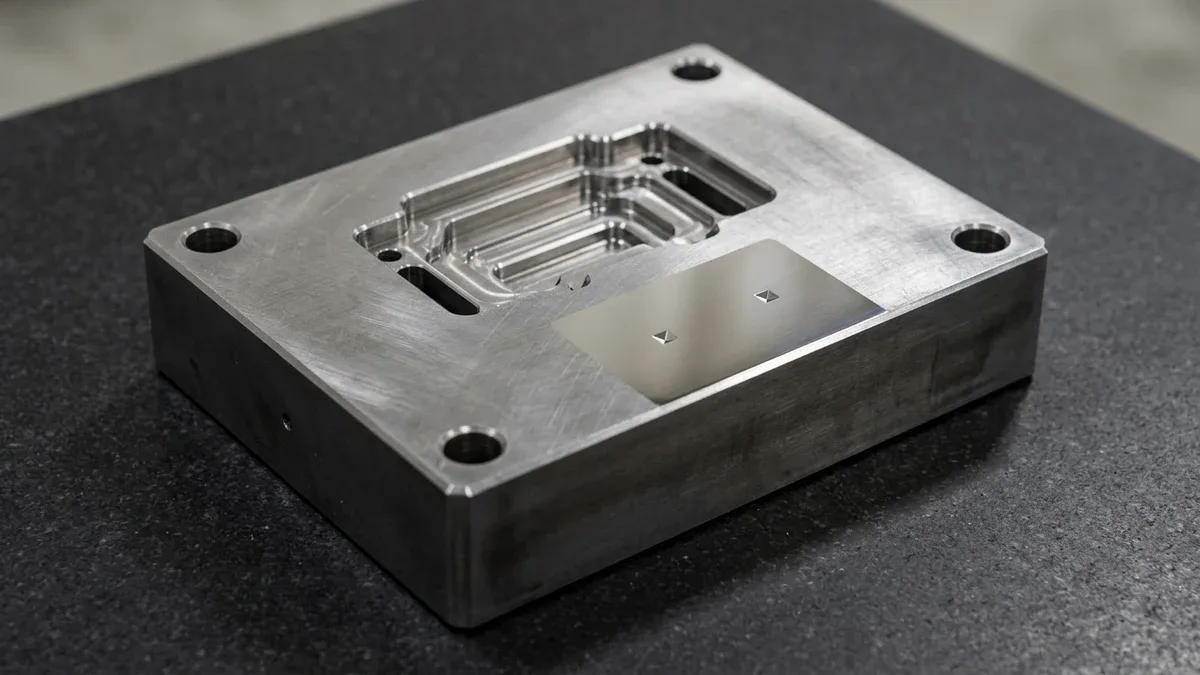
For localized case-depth and thin-section evaluation, Figure 2 shows a surface-ground hardened tool steel stamping die block resting flat on black granite with two microscopic square-pyramid Vickers hardness indentations. Optical measurement of the pyramid diagonals per ASTM E384 quantifies surface hardness without fracturing thin functional edges.
4. Hardness vs. Hardenability: Key Distinctions in Heat Treatment
One of the most frequent misconceptions encountered in manufacturing drawings is confusing hardness with hardenability:
- Hardness: The actual physical property of a material measuring its surface resistance to indentation at a specific location. Hardness is primarily a function of the carbon content in the martensite lattice after quenching, followed by tempering relaxation.
- Hardenability: The relative ability of a steel alloy to form martensite at depth when quenched from the austenitizing temperature. Hardenability is governed by alloying elements (Chromium, Molybdenum, Nickel, Manganese, and Boron), which delay the pearlite/bainite transformation nose on continuous cooling transformation (CCT) diagrams.
- The Jominy End-Quench Test (ASTM A255): Hardenability is experimentally quantified using the Jominy test. A standardized Ø1-inch round bar is austenitized, secured vertically in a fixture, and quenched solely on its bottom face by a calibrated water jet. Hardness measurements (HRC) are taken along the longitudinal grind flat at specified intervals from the quenched end to create a hardenability curve. High-hardenability steels (like 4340 or 300M) maintain high hardness deep into thick cross-sections, whereas shallow-hardening steels (like 1045) form a hard skin over a soft, ferrite-pearlite core.
5. Manufacturing Strategies for Machining Hard Materials
When engineering designs specify parts with hardnesses exceeding 45 HRC to withstand heavy rolling contact or abrasive wear, standard milling and turning techniques become unviable due to catastrophic tool wear, thermal chipping, and severe vibration. At AS Prototypes, our facilities execute three specialized manufacturing pathways:
1. Pre-Hardening Roughing followed by Finish Stress Relieving
Whenever practical, parts are rough-machined in their annealed or normalized condition (typically 180–240 HBW), leaving a uniform finishing stock allowance of 0.3 mm to 0.5 mm on critical datum planes and diameters. The part then undergoes vacuum heat treating and tempering to the final required hardness (e.g., 58–62 HRC for D2 or 8620). Any distortion induced by thermal phase transformation is subsequently eliminated during final precision grinding.
2. High-Precision CNC Grinding
For hardened shafts, bearing journals, precision slideways, and punch faces, high-precision CNC surface and cylindrical grinding remains the gold standard. Utilizing vitrified cubic boron nitride (CBN) or ceramic-grain abrasive wheels with high-pressure synthetic flood cooling, our grinding centers maintain tight micron-level dimensional tolerances (±0.005 mm / ±0.0002″) and mirror-like finishes down to Ra 0.1 μm without generating thermal micro-cracks.
3. Hard Turning and High-Speed Hard Milling
Modern polycrystalline cubic boron nitride (PCBN) and coated whisker-reinforced ceramic inserts enable “hard machining” of steels up to 65 HRC directly on rigid 5-axis CNC machining centers. Hard milling eliminates EDM recast layers, maintains tight true-position tolerances across complex 3D mold surfaces, and delivers lead-time reductions of over 40% compared to traditional electrode fabrication.
By pairing rigorous incoming metallurgical hardness verification with advanced precision CNC machining and grinding technologies, engineering teams ensure their components survive the most demanding mechanical operating conditions without unexpected premature failure.
🔗 Related Heat Treatment, Grinding & Metallurgy Engineering Guides:
For hardened tool steels, precision bearing shafts, and wear-resistant dies, explore our high-precision CNC surface and cylindrical grinding services and Wire EDM machining, or read our technical guides on Annealing & Heat Treatment Metallurgy, Steel Heat Treatment & CNC Distortion Control, and Precision CNC Steel Machining & Alloy Selection.
6. Technical Engineering FAQ
Commercial vacuum furnaces, induction coils, and tempering ovens experience natural thermal gradients, and alloy steel heats vary slightly in carbon content within ASTM tolerances. Furthermore, ASTM E18 Rockwell testers have a repeatability tolerance of ±0.8 to ±1.0 HRC. Specifying a realistic 2 to 4 HRC window (such as 58–60 HRC for D2 tool steel or 28–32 HRC for 4140 shafts) prevents unnecessary batch rejection.
Rockwell C applies a heavy 150 kgf (1,471 N) major load that punches through thin surface layers and sheet metal under 1.0 mm (0.040″) thick, measuring the soft underlying core or steel anvil instead of the surface. You must specify Vickers microhardness (HV0.05 to HV0.5 per ASTM E384) when verifying MIL-A-8625 Type III hard anodize (≥400 HV), electroless nickel plating, gas nitrided skins (0.1–0.3 mm deep), or micro-Swiss shafts.
Hardness measures the maximum surface resistance to plastic indentation achieved after quenching—which is governed almost entirely by the steel’s carbon percentage (e.g., 1045 vs. 4140 both reach ~58 HRC at the surface). Hardenability measures how deeply that martensitic hardness penetrates from the surface to the core during quenching, which is governed by alloying elements like Chromium, Molybdenum, and Nickel (4340 through-hardens thick cross-sections; 1045 only hardens a shallow skin).
For components requiring 52 to 62 HRC, we first rough-machine the annealed stock on 3/4-axis CNC centers leaving 0.25 to 0.40 mm (0.010″ to 0.016″) grinding/finishing allowance, perform vacuum quenching and triple tempering, verify hardness per ASTM E18/E384 on witness coupons or non-critical flats, and finish-machine critical datums via CNC cylindrical/surface grinding, Wire EDM, or PCBN hard turning to ±0.005 mm (±0.0002″).
Ready to Validate Your CAD Design for Precision Manufacturing?
Upload your 3D CAD models (STEP, IGES, SolidWorks) and 2D engineering drawings for a comprehensive DFM engineering review and custom quotation from our in-house CNC machining and prototyping team.
Request a Custom DFM Review & Quote →