In high-precision manufacturing, mechanical components rarely fail solely because of dimensional inaccuracies; they fail because of unseen, locked-in internal stresses and unfavorable crystal lattice microstructures. Whether dealing with cold-drawn alloy steel bars, heavy closed-die forgings, thin-walled aerospace aluminum hog-outs, or optical-grade polycarbonate manifolds, raw materials and heavily machined parts carry severe residual stresses.
Left unaddressed, these internal stresses trigger post-machining warpage, spontaneous stress-corrosion cracking, tool-shattering work hardening, and premature catastrophic fatigue failure in service. In precision manufacturing, mastering what is annealing ensures repeatable dimensional stability and predictable production scaling.
To eliminate these vulnerabilities, metallurgical engineers deploy annealing—one of the most critical and versatile thermal conditioning processes in materials science. But exactly what is annealing, how does it alter atomic crystal lattices, and how does it integrate with precision CNC machining to achieve dimensional tolerances down to ±0.01 mm?
At AS Prototypes, with more than ten years of precision prototyping, multi-axis CNC machining, and comprehensive thermal post-processing expertise, our engineering facility executes verified thermal treatments to guarantee dimensional stability across mission-critical aerospace, automotive, medical, and robotics applications. This comprehensive engineering guide examines the three kinetic stages of annealing metallurgy, contrasts the primary industrial annealing classifications, provides an alloy-by-alloy thermal processing matrix, and outlines how strategic intermediate stress-relief annealing prevents part distortion during precision CNC machining.
- Core Focus & DFM Scope: Actionable shop-floor engineering guidelines for what is annealing, covering material selection, geometric tolerancing, and defect prevention.
- Coating Buildup & Allowance: MIL-A-8625 Type II anodizing adds 5–15 µm (0.2–0.6 mil) per face; Type III hardcoat adds 25–50 µm (1.0–2.0 mil) with 50% inward penetration and 50% outward growth.
- Roughness & Tribological Control: Pre-finish machining to Ra 0.4–0.8 µm (16–32 µin) per ISO 4287 / ASME B46.1, paired with ASTM B117 neutral salt spray and ASTM E384 microhardness validation.
- Precision Masking & Thread Protection: Silicone plug masking and pre-plate pitch-diameter allowance on H7 bores and M-series / UN threads to maintain post-coating gauge fit.
- Ex-Factory Turnaround: 7 to 12 business days for CNC machined components with complete surface finishing, passivation, or heat treatment verification (excluding 3–5 days air transit).
What is Annealing? The Thermodynamic Definition
At its fundamental thermodynamic level, annealing is a heat treatment process in which a material (metallic alloy, engineering thermoplastic, or technical glass) is heated to a predetermined critical temperature, soaked (held) at that temperature for a calculated dwell period, and subsequently cooled at a controlled, slow rate (typically inside a sealed furnace or insulated medium).
The primary objectives of industrial annealing include:
- Relieving Internal Residual Stresses: Dissipating microscopic stresses induced by casting solidification, plastic deformation (rolling, drawing, stamping), welding thermal gradients, or heavy CNC roughing.
- Restoring Ductility & Fracture Toughness: Softening cold-worked metals to allow subsequent severe plastic forming without edge tearing or cracking.
- Refining Microstructural Homogeneity: Eliminating chemical segregation, dendritic casting coring, and anisotropic grain elongation to produce uniform, equiaxed grains.
- Optimizing Machinability: Transforming hard, brittle, or abrasive microstructures (such as laminar pearlite or acicular martensite) into easily sheared spheroidal carbide configurations, extending CNC tool life and improving surface finish (Ra).
The 3 Kinetic Stages of Annealing Metallurgy
When a deformed, strain-hardened metallic crystal lattice is subjected to annealing temperatures, it traverses three distinct physical and microstructural regimes governed by thermal activation kinetics:
1. Recovery (Low-Temperature Regime)
Occurring at temperatures below the recrystallization threshold (T < 0.3–0.4 Tm in Kelvin), recovery is driven by the stored strain energy of cold work. At this temperature, thermal energy enables point defects (vacancies) to diffuse and dislocations to move via climb and cross-slip. Oppositely charged dislocations annihilate, and surviving dislocations rearrange themselves into lower-energy sub-grain polygonal cell boundaries (polygonization).
Engineering Result: Up to 50% of internal residual stresses are relieved, and electrical conductivity is restored, with virtually no change in overall hardness or optical grain morphology.
2. Recrystallization (Core Microstructural Transformation)
When the temperature exceeds the material’s critical recrystallization temperature (Trx ≈ 0.4–0.5 Tm for pure metals, 0.5–0.6 Tm for complex alloys), a profound metallurgical transformation occurs. High-energy dislocation cell walls serve as nucleation sites for entirely new, strain-free, equiaxed crystal grains.
These new nuclei consume and replace the heavily deformed, elongated grains of the cold-worked matrix. As the strain-free grains grow and impinge upon one another, the accumulated dislocation density plummets from 1011–12 cm-2 down to 106–8 cm-2.
Engineering Result: Hardness and yield strength drop sharply, while elongation, ductility, and impact energy absorption are fully restored to baseline values.
3. Grain Growth (High-Temperature Coarsening)
If the material is held at elevated temperatures after recrystallization is complete, the microstructure continues to evolve through grain boundary migration. Because grain boundaries possess surface free energy, the system minimizes its total interfacial energy by eliminating boundaries—meaning larger grains grow at the expense of smaller grains.
The Hall-Petch Trade-off: While moderate grain growth enhances ductility, excessive grain growth is detrimental. According to the Hall-Petch relationship (σy = σ0 + ky d-1/2), coarse grains significantly lower mechanical yield strength and produce a rough “orange-peel” surface texture during secondary bending or deep drawing. Precise digital furnace soak-time control is critical to arresting grain growth at the optimal ASTM grain size (ASTM 6 to 8).
Major Industrial Types of Annealing Processes
Depending on the alloy composition, prior processing history, and specific manufacturing objectives, industrial heat treaters deploy tailored annealing cycles:
1. Full Annealing (Complete Austenitization)
Applied primarily to hypoeutectoid carbon and alloy steels (e.g., AISI 1045, 4140, 8620). The steel is heated to approximately 30°C to 50°C above the upper critical transformation line (Ac3).
After soaking until fully transformed into homogeneous austenite, the furnace is powered down, and the steel cools extremely slowly inside the refractory furnace (cooling rates ≤ 15°C–25°C/hour) down to below 500°C. This slow equilibrium cooling transforms the austenite into a coarse, lamellar pearlite and ferrite matrix, yielding minimum hardness and maximum ductility.
2. Isothermal Annealing (High-Efficiency Cycle)
Full annealing requires massive furnace cycle times (often 16 to 24 hours). Isothermal annealing optimizes this cycle: the component is austenitized above Ac3, rapidly cooled to an intermediate temperature just below the pearlite transformation nose (650°C–680°C), and held isothermally until the austenite completely decomposes into uniform pearlite. Once transformation is complete, the part can be rapidly air-cooled. Isothermal annealing cuts furnace cycle times by 60% while producing exceptionally uniform microstructures across complex gear forgings and drive shafts.
3. Spheroidizing Annealing (Tool Steels & Bearing Steels)
High-carbon steels (>0.6% C) and tool steels (AISI D2, A2, O1, 52100) contain dense networks of hard, plate-like cementite (iron carbide) that rapidly dull and fracture CNC cutting tools. Spheroidizing involves heating the steel just around the lower critical temperature line (Ac1 ≈ 740°–780°C) for extended durations (often 8 to 15 hours).
Surface tension forces cause the continuous cementite plates to break up and coalesce into spherical, globular carbide balls embedded in a ductile ferrite matrix. This drops hardness to under 200 HB, transforming an unmachinable blank into a free-cutting workpiece with outstanding tool life.
4. Stress-Relief Annealing (Subcritical Conditioning)
Operating below the lower critical temperature (550°C–650°C for steels; 300°C–350°C for brass; 300°C–380°C for aluminum alloys), stress-relief annealing involves no phase changes. Its sole purpose is thermal dislocation relaxation. It is indispensable for welded assemblies, complex cast housings, and asymmetric aerospace billets prior to final CNC finishing passes.
5. Bright Annealing (Atmosphere-Controlled)
When stainless steels (304, 316L) or copper alloys are annealed in ambient air, oxygen and moisture react with surface chromium and copper, forming thick black scale and surface decarburization. Bright annealing is executed in sealed retort furnaces under high-purity hydrogen (H2), dissociated ammonia (75% H2 + 25% N2), or high vacuum (< 10-4 mbar). The reducing atmosphere prevents oxidation, discharging parts with pristine, mirror-reflective metallic luster ready for cleanroom medical or semiconductor assembly.
6. Engineering Polymer Thermal Annealing
Plastics also require annealing! Extruded and injection-molded semi-crystalline and amorphous thermoplastics (Polycarbonate, Acrylic PMMA, POM Delrin, PEEK, Ultem) lock in severe polymer chain orientation stresses. At AS Prototypes, we anneal machined plastic components in digital convection ovens:
- Polycarbonate (PC): Soaked at 120°C–125°C followed by slow cooling at ≤ 10°C/hr to eliminate crazing and chemical stress cracking during vapor polishing.
- PEEK: Conditioned at 200°C to release roughing stresses, ensuring tight ±0.01 mm bore tolerances.
- Acrylic (PMMA): Soaked at 80°C–85°C to prevent micro-cracking during precision drilling.
Comprehensive Engineering Comparison Matrix: Heat Treatment Processes
To assist mechanical engineers and procurement specialists in selecting the exact heat treatment specification for their blueprints, the comparison table below contrasts annealing with other primary industrial thermal processes:
| Heat Treatment Process | Soaking Temperature | Cooling Environment & Rate | Resulting Microstructure | Mechanical Property Impact | Typical Application in CNC Production |
|---|---|---|---|---|---|
| Full Annealing | Ac3 + 30°C ~ 50°C | Furnace cooling (≤20°C/hr) | Coarse pearlite + ferrite | Lowest hardness, maximum ductility, high toughness | Raw bar stock and forged blanks prior to heavy CNC roughing operations. |
| Stress-Relief Anneal | 550°C ~ 650°C (subcritical) | Slow furnace cooling to 300°C, then air | Unaltered parent matrix (dislocation relaxation) | Relieves 85%–95% internal stress without hardness loss | Intermediate cycle between rough CNC milling and final finishing on tight-tolerance housings. |
| Normalizing | Ac3 + 50°C ~ 80°C | Still air cooling at ambient room temp | Fine lamellar pearlite + uniform ferrite | Higher yield strength and hardness than full anneal; uniform grain size | Structural beams, heavy forgings, and weldments to establish baseline grain uniformity. |
| Quenching (Hardening) | Ac3 + 30°C ~ 50°C | Rapid quench (water, oil, or high-pressure gas) | Tetragonal martensite (untempered) | Maximum hardness (55–65 HRC), extreme brittleness, high residual stress | Always immediately followed by tempering; unmachinable except via hard milling or EDM. |
| Tempering | 150°C ~ 650°C (post-quench) | Air cooling | Tempered martensite / fine carbide dispersion | Balances high tensile strength with restored impact toughness | Drive gears, precision shafts, fasteners, and structural aircraft landing gear components. |
| Precipitation Hardening | Solutionize @ 1040°C + Age @ 480–620°C | Air or inert gas cooling | Coherent sub-microscopic intermetallic precipitates | Ultra-high yield strength (>1100 MPa) with excellent corrosion resistance | 17-4PH stainless valves, 6061-T6 aluminum, and Inconel 718 turbine components. |
Integrating Annealing with CNC Machining: The Zero-Warp Protocol
When machining high-precision parts featuring large material removal ratios (such as pocketed aerospace brackets or thin-walled optical housings), removing outer metal unbalances the internal residual stresses of the raw stock. The component immediately bows or twists upon release from the machine vise.
At AS Prototypes, we solve this through our verified Zero-Warp Protocol:
- Raw Stock Sourcing & Ultrasonic Testing: Procure verified, pre-stretched plate stock (e.g., 6061-T651 or 7075-T651, where controlled mechanical stretching relieves initial quenching stresses).
- Stage 1 Rough CNC Machining: Perform aggressive dynamic roughing, leaving a uniform +1.5 mm to +2.0 mm sacrificial envelope across all surfaces. This releases 70% of locked-in bulk material stresses.
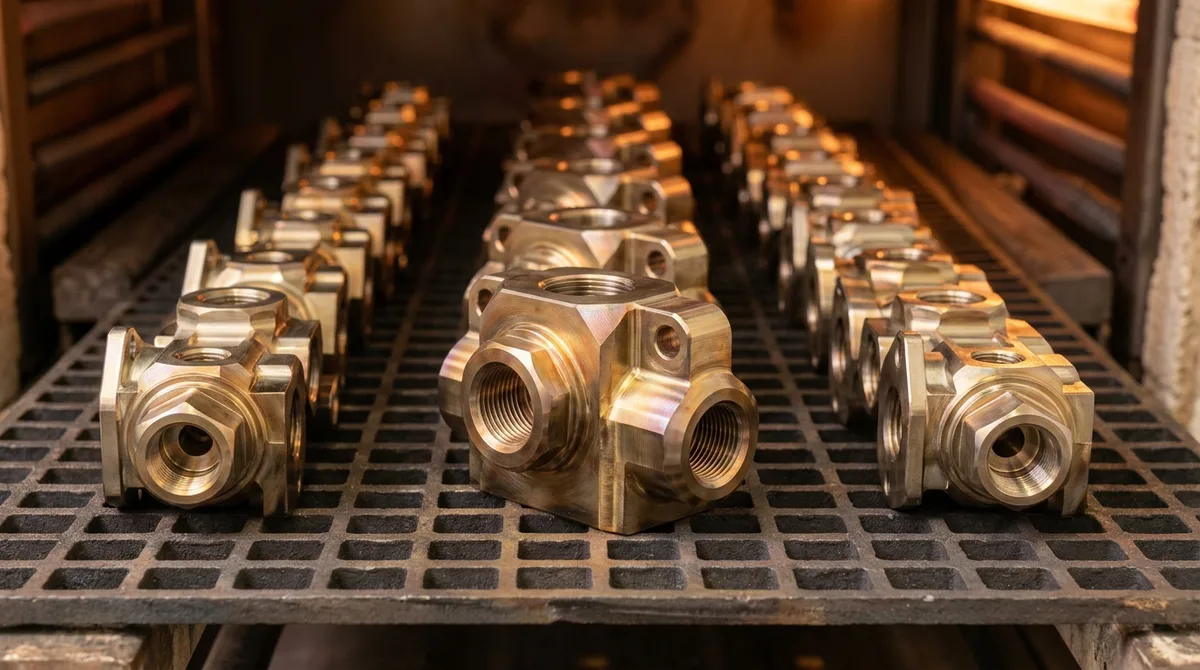
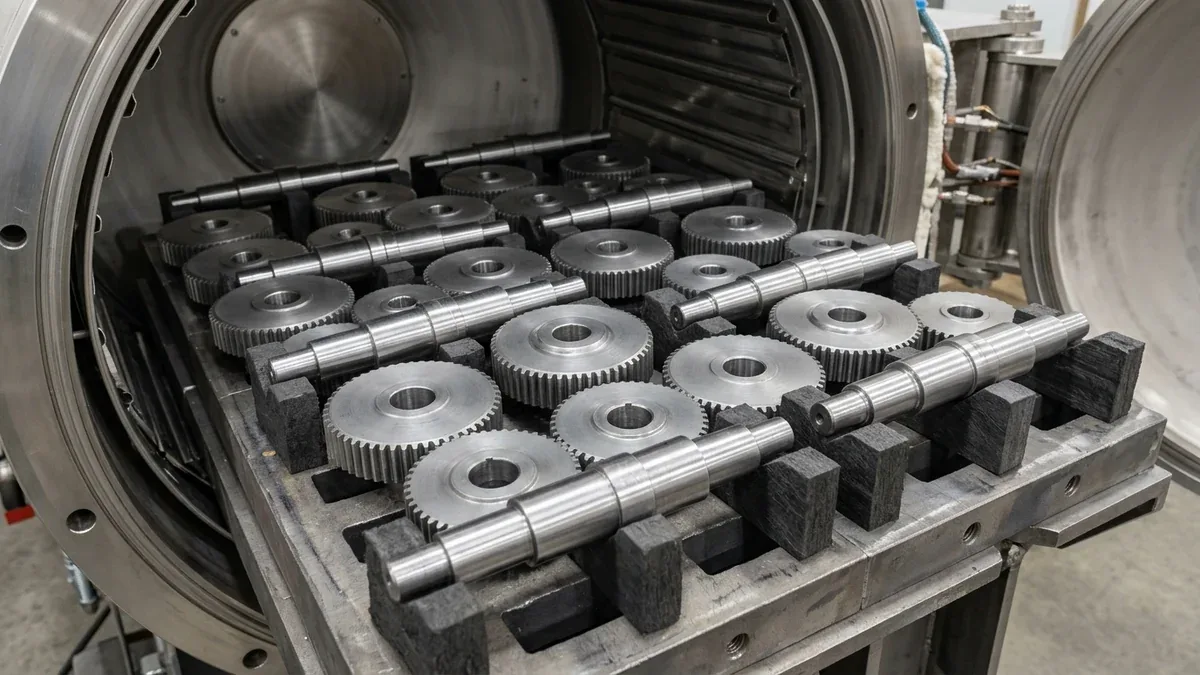
- Intermediate Vacuum Stress-Relief Annealing: Transfer the rough-machined parts to our computer-controlled vacuum atmosphere furnace. Components are heated at calibrated ramp rates (100°C/hr), soaked for 2 to 4 hours, and cooled inside the furnace. This completely relaxes cutting-induced dislocations without surface scaling or dimensional distortion.
- Stage 2 Semi-Finishing: Re-clamp the stress-free part on calibrated datum faces and true all geometric surfaces, leaving +0.25 mm finishing stock.
- Stage 3 High-Speed 5-Axis Finishing: Execute light finish passes with balanced climb milling. The resulting component achieves dimensional tolerances within ±0.01 mm and maintains absolute geometric flatness across years of operational service.
Shop-Floor Cost-Tolerance Trade-Offs & When NOT to Over-Specify
When releasing production drawings for what is annealing, applying blanket ±0.005 to ±0.010 mm (±0.0002″ to ±0.0004″) tolerances across non-mating clearance features increases machining cycle time by 2.0× to 3.5× without improving assembly performance. Our DFM engineers recommend specifying ISO 2768-mK on general structural walls while isolating tight GD&T callouts strictly to functional bearing bores, dowel pins, and sealing interfaces.
In our Shenzhen facility, prismatic 3-axis and 4-axis vertical machining centers (VMCs) with contoured soft jaws handle 80%+ of structural setups with maximum rigidity and cost efficiency, reserving simultaneous 5-axis contouring strictly for compound-angle ports and organic impellers. Every batch undergoes climate-controlled 20°C (68°F) Zeiss CMM verification prior to ex-factory release (4 to 8 business days for raw prototypes; 7 to 12 business days with MIL-A-8625 anodizing or ASTM A967 passivation).
🔗 Related CNC DFM & Metrology Engineering Guides:
To further optimize cycle time and dimensional stability in what is annealing, combine proper internal corner relief with datum-based coordinate inspection. Consult our shop-floor engineering guides on Maintaining Dimensional Stability in Thin-Wall Machining, Eliminating Sharp Internal Corners & Tool Deflection, and Precision CMM Metrology & GD&T Verification.
Frequently Asked Questions (FAQ)
How long does an industrial annealing cycle typically take?
Total annealing cycle times range from 4 hours to over 24 hours depending on the material, component cross-sectional thickness, and annealing type. Spheroidize and full annealing of thick tool steels require extended soak times and ultra-slow furnace cooling (12 to 20 hours), whereas subcritical stress-relief annealing of aluminum or thin steel parts can complete in 4 to 6 hours.
Can annealing be reversed if a part needs to be hardened later?
Yes. Annealing softens steel by producing equilibrium pearlite and ferrite microstructures. If the final component requires high surface hardness or wear resistance (such as a gear tooth or bearing journal), it can subsequently undergo quenching and tempering, carburizing, or induction hardening to achieve required hardness levels (up to 58–62 HRC).
Why is annealing critical before vapor polishing polycarbonate?
Polycarbonate (PC) is exceptionally sensitive to Environmental Stress Cracking (ESC). When exposed to chemical solvent vapors during vapor polishing, any locked-in machining stress triggers explosive micro-crazing and milky surface whitening. Thermal annealing at 120°C dissipates these internal polymer stresses, ensuring crystal-clear optical transparency.
Partner with AS Prototypes for Precision CNC Machining & Heat Treatment
Need tight-tolerance metal or plastic components that maintain absolute dimensional stability under extreme operating loads? AS Prototypes integrates high-speed 5-axis CNC machining, verified vacuum atmosphere annealing, and rigorous quality management verified quality managementmetrology inspection to deliver stress-free, micrometer-accurate parts with tolerances down to ±0.01 mm.
Request an Engineering DFM Review & Quote →Upload your 3D CAD models (STEP/IGES) and 2D engineering drawings to receive a comprehensive technical review and quotation within 24 hours.
We combine dynamic trochoidal high-speed clearing (HSM), optimized chip thinning feed compensation, and 5-axis simultaneous contouring to reduce cutting forces, suppress harmonic chatter, and maintain tight dimensional repeatability across thin walls.
We utilize high-rigidity hydraulic and shrink-fit tool holders, high-pressure through-spindle coolant (70 bar), and temperature-stabilized linear optical glass scales that compensate for machine axis thermal drift in real time.
Rapid CNC functional prototypes are completed ex-factory in 4 to 8 business days, with engineering DFM analysis and formal quotations returned within 24 hours of 3D CAD submission.