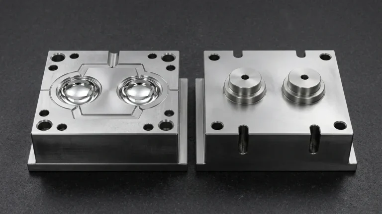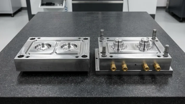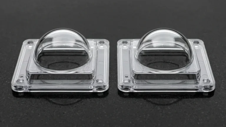
In high-reliability hardware manufacturing—spanning commercial flight-control actuators, surgical robotics, and semiconductor vacuum chambers—dimensional compliance cannot rely on spot-checks. An uncompensated cutter deflection, an unverified billet heat lot, or an uncalibrated anodizing bath can scrap an entire assembly run. To eliminate systemic production risk before scaling volume, engineering teams mandate a rigorous first article inspection protocol.
Structured around a Ballooned Drawing & Full-Dimensional FAI Report (Form 1 / Form 2 / Form 3), a formal first article inspection (FAI) audits both the physical workpiece and the manufacturing process. Rather than checking isolated critical-to-quality (CTQ) features, an FAI mandates 100% accountability across every blueprint callout, geometric tolerance, alloy heat lot, and surface treatment.
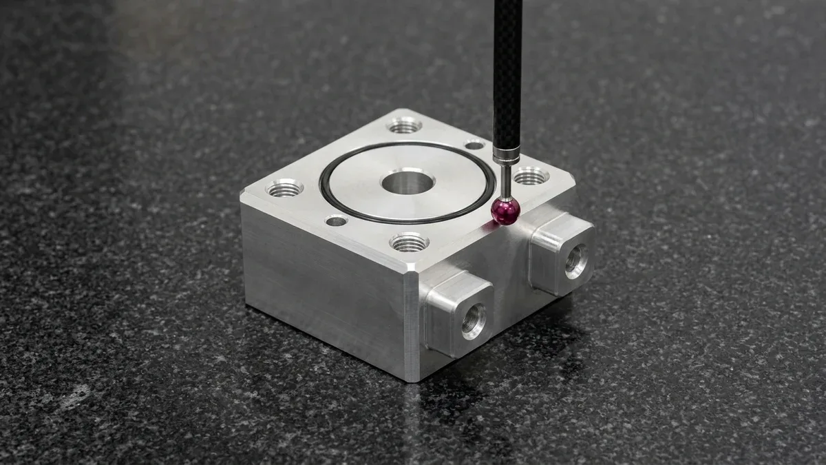
At our Shenzhen CNC facility, our quality engineers integrate ballooned 2D prints, X-ray fluorescence (XRF) alloy testing, and automated Zeiss Contura bridge Coordinate Measuring Machine (CMM) routines across our precision CNC machining services. We verify general features to ISO 2768-mK and critical bearing bores or dowel holes to ±0.010 mm to ±0.020 mm (±0.0004″ to ±0.0008″).
Executive Summary & Engineering Takeaways (BLUF)
- Three-Form FAI Accountability Structure: A complete Full-Dimensional First Article Inspection Report (FAIR) unites Form 1 (Part & BOM Accountability), Form 2 (EN 10204 Type 3.1 Raw Material MTRs & Special Process Traceability), and Form 3 (100% Ballooned Characteristic Verification).
- Shop-Floor Workhorse & Tolerance Realism: High-speed 3-axis and 4-axis VMCs machine 80%+ of prismatic manifolds and brackets to ISO 2768-mK general tolerances and ±0.010 mm to ±0.020 mm (±0.0004″ to ±0.0008″) bearing fits, while Wire EDM and cylindrical grinding hold ±0.005 mm (±0.0002″).
- Metrology Instrument Matching: Rigid metal GD&T features are probed on climate-controlled 20°C ± 1°C (68°F ± 1.8°F) bridge CMMs, whereas flexible sheet metal stampings (DIN 6935) and polymer 3D prints are verified via non-contact 2.5D Optical Vision Measurement Systems (VMS) and fit-up fixtures.
- Delta FAI Efficiency: When an Engineering Change Order (ECO) modifies isolated features on an active part, executing a Delta (Partial) FAI isolates Form 3 re-inspection strictly to affected balloon numbers, cutting metrology overhead by 60%–75%.
- Predictable Ex-Factory Turnaround: As-machined CNC prototypes with full FAIR documentation complete ex-factory production and inspection in 4 to 8 business days (7 to 12 business days with surface finishing), separate from 3 to 5 business days air transit.
Article Engineering Navigation
- 1. Physical Principles & Scope of First Article Inspection
- 2. Three-Form FAI Architecture: Form 1, Form 2 & Form 3
- 3. Ballooned 2D Drawings & Characteristic Mapping
- 4. True Position, MMC Bonus, Gauge Cg/Cgk & Thermal Math
- 5. Shop-Floor Metrology & Tolerance Verification Matrix
- 6. FAI Rejection Root Causes, DFM & Process Trade-Offs
- 7. Ex-Factory Turnaround & CAD Submission Checklist
- 8. Technical Engineering FAQ
1. Physical Principles & Industrial Scope of First Article Inspection (FAI)
In contract CNC manufacturing, a first article inspection validates a representative component from the initial production run built with standard tooling, fixturing, NC code, and shop routing. Unlike outgoing spot-checks of 5 to 15 CTQ features, an FAI verifies 100% of linear dimensions, radii, threads, surface roughness (Ra / Rz per ISO 4287), and drawing notes.
In our in-house shop-floor operations, 75% to 85% of precision prismatic enclosures, optical mounts, and hydraulic manifolds are machined on high-speed 3-axis and 4-axis vertical machining centers using precision steel vises or custom CNC-milled aluminum soft jaws. Simultaneous 5-axis CNC machining centers are strategically deployed for compound-angle manifolds, impellers, and contoured aerospace structural components.
2. Three-Form FAI Accountability Architecture: Form 1, Form 2, and Form 3 Breakdown
The industry benchmark for first article inspection documentation is the Ballooned Drawing & Full-Dimensional FAI Report (Form 1 / Form 2 / Form 3 Layout). Digital FAI workflows link inspection planning to the shop router and require Form 1 sign-off only after all Form 2 material test reports and Form 3 dimensional readings are 100% reconciled.
Form 1 (Part Accountability) logs the part number, revision, PO, serial/lot ID, BOM index, and Full vs. Delta FAI status. Form 2 (Product Accountability) verifies raw alloys (6061-T6, 7075-T651, 17-4PH, 316L, Ti-6Al-4V) via XRF and EN 10204 3.1 MTRs alongside special finishes (MIL-A-8625 Type II/III, MIL-DTL-5541, ASTM A967, and ASTM E18).
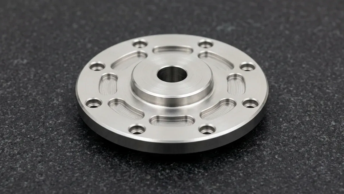
Form 3 (Characteristic Accountability) records every ballooned print callout (#1–#N) with its zone, nominal dimension, tolerance limits, measured reading, and calibrated gauge ID. On a turn-mill machined 17-4PH stainless steel rotary harmonic adapter flange, Form 3 logs the central reamed pilot bore, raised spigot boss, eight counterbored bolt-circle holes, and eight radial kidney-shaped lightening pockets.
| FAI Report Artifact / Mode | Core Engineering Data Captured | Shop-Floor Verification Evidence | Mandatory Triggering Events | Recommended Application / When to Choose |
|---|---|---|---|---|
| Form 1: Part Accountability | Part number, drawing revision, PO, serial/lot ID, Full vs. Delta status, BOM index | Shop router log, CAD/PDF revision reconciliation check, QA lead sign-off | Every Full or Delta FAI submission across detail parts and assemblies | Mandatory master cover sheet locking configuration and revision traceability |
| Form 2: Product Accountability | Raw alloy heat lots, special surface finishes, heat treatment, functional tests | EN 10204 3.1 MTRs, XRF PMI spectra, coating thickness & ASTM E18 hardness logs | New alloy heat lot, special process bath, or pressure/leak test requirement | Choose whenever alloy chemistry, temper hardness, or MIL/ASTM plating is critical |
| Form 3: Characteristic Audit | Sequential balloons (#1–#N), drawing zones, nominal/tolerance limits, actual readings | Bridge CMM coordinate reports, 2.5D VMS logs, bore micrometer & thread plug records | 100% of features on Full FAI; modified features only on Delta FAI | Essential for validating GD&T datums and ±0.010 mm (±0.0004″) mating fits |
| Full FAI Submission | Complete Forms 1, 2, and 3 covering 100% of blueprint callouts and notes | Full ballooned 2D PDF drawing + complete CMM/gauge dataset + MTRs | New part introduction (NPI), shop relocation, or production lapse ≥ 24 months | Choose when transitioning a new part from prototyping into production |
| Delta (Partial) FAI | Form 1 referencing baseline FAIR + Form 2/3 limited strictly to revised features | Delta ballooned print highlighting changed callouts + targeted CMM re-check | Drawing revision bump (Rev A to Rev B), NC toolpath shift, or fixture change | Choose during iterative ECO revisions to avoid re-inspecting unchanged features |
3. Ballooned 2D Engineering Drawings & Characteristic Accountability Mapping
A Ballooned Engineering Drawing maps every 2D print feature to FAI Form 3. When one callout governs multiple parameters—such as 4× ⌀8.00 +0.015/-0.000 mm THRU, ⌴ ⌀14.0 × 8.5 mm DEEP, True Position ⌀0.025 mm |A|B|C—our engineers assign sub-balloons (#12.1–#12.4) and log individual readings (#12.1a–d) for each hole without averaging.
4-Step Shop-Floor SOP for Executing a Full-Dimensional First Article Inspection
- Reconcile 3D CAD, 2D Revision & Raw Alloy Lot: Cross-check the 3D STEP model against the 2D PDF revision block, verify default tolerances (ISO 2768-mK), and perform XRF alloy testing against the EN 10204 Type 3.1 Mill Test Report before cutting stock.
- Generate Grid-Indexed Balloon Drawing: Divide the 2D print into alphanumeric zones (A1–D8) and assign sequential balloon numbers (#1 to #N) clockwise across all views, including title-block general notes (edge break, surface roughness, and thread class).
- Execute Thermal Soak & Multi-Gauge Probing: Ultrasonic-clean the finished part, stabilize it for 4 hours in our 20°C ± 1°C (68°F ± 1.8°F) metrology lab, and run automated bridge CMM routines alongside 3-point bore micrometers, pin gauges, and profilometers.
- Compile, Audit & Lock FAI Forms 1, 2, and 3: Record actual quantitative measurements and calibrated gauge IDs on Form 3, attach Form 2 material/coating reports, verify 100% conformance, and sign off Form 1 before releasing batch production.
4. Mathematical Derivation: True Position, MMC Bonus, Gauge Capability & Thermal Compensation
Eliminating measurement disputes during first article inspection requires rigorous mathematical models for Cartesian-to-diametral True Position (TP), Maximum Material Condition (MMC) bonus tolerance (ASME Y14.5 / ISO 1101), Gauge Capability (Cg / Cgk), and ISO 1 thermal expansion compensation at 20°C ± 1°C (68°F ± 1.8°F).
TPactual = 2 × √( (ΔX)2 + (ΔY)2 ) | Ttotal = Tgeometric + | Dactual − DMMC |
Rgauge = ( 2 × U95 ) ÷ T ≤ 0.20 | Cg = ( 0.20 × T ) ÷ ( 6 × sg ) ≥ 1.33 | Cgk = ( 0.10 × T − |x̄g − xref| ) ÷ ( 3 × sg ) ≥ 1.33
ΔL = α × L × ΔT = α × L × ( Tpart − 20°C )
- ΔX, ΔY, Dactual, DMMC: Measured coordinate offsets and feature diameters vs. MMC limit, in mm (in).
- U95, T = (USL − LSL), sg, |x̄g − xref|: Expanded 95% CMM uncertainty, total tolerance width, gauge repeatability standard deviation, and master ring calibration bias.
- α, L, ΔT: Linear coefficient of thermal expansion (e.g., 23.2 × 10⁻⁶ /K for 7075-T651 aluminum), nominal length L, and temperature offset from 20°C (68°F).
Worked Shop-Floor Calculation Example (Metric & Imperial)
Consider a 7075-T651 manifold bore specified at ⌀10.000 +0.025/−0.000 mm (0.3937″ +0.0010″/−0.0000″) with True Position ⌀0.020 mm (0.0008″) at MMC (Ⓜ) to Datums A|B|C (DMMC = 10.000 mm, T = 0.025 mm). Our bridge CMM probes Dactual = 10.016 mm (0.3943″) at offsets ΔX = +0.009 mm (+0.00035″) and ΔY = −0.008 mm (−0.00031″).
Diametral true position evaluates to TPactual = 2 × √((0.009)2 + (−0.008)2) = 0.0241 mm (0.00095″). Although 0.0241 mm exceeds 0.020 mm under RFS, the MMC departure grants a 0.016 mm (0.00063″) bonus, expanding total positional tolerance to Ttotal = 0.020 + 0.016 = 0.036 mm (0.00142″) so the bore passes Form 3.
With CMM uncertainty U95 = 0.0021 mm, repeatability sg = 0.0004 mm, and master ring bias 0.0005 mm across T = 0.025 mm, the measurement capability ratios evaluate to Rgauge = 0.168 ≤ 0.20, Cg = 2.08 ≥ 1.33, and Cgk = 1.67 ≥ 1.33.
If this L = 250.000 mm (9.8425″) 7075-T651 manifold (α = 23.2 × 10⁻⁶ /K) is probed warm at 28°C (82.4°F, ΔT = +8°C), thermal growth reaches ΔL = +0.0464 mm (+0.00183″), falsely rejecting a ±0.020 mm tolerance. A 4-hour soak at 20°C ± 1°C cuts drift to ≤ 0.0058 mm (0.00023″).
5. Shop-Floor Metrology Instrumentation & Tolerance Verification Matrix
Populating FAI Form 3 with defensible data requires matching each geometric characteristic to an inspection instrument whose resolution satisfies the 10:1 to 4:1 gauge capability rule. In our climate-controlled Shenzhen quality laboratory, our engineers select from our in-house metrology and CNC equipment list based on feature geometry, material stiffness, and tolerance width.
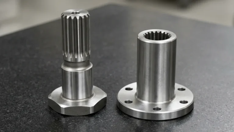
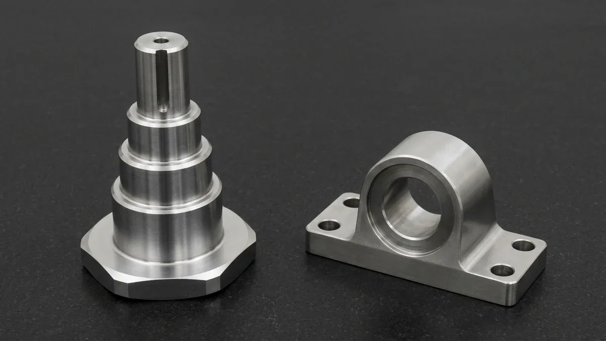
For rotational drive parts—such as a CNC-turned and cylindrical-ground 4140 alloy steel four-stepped transmission spindle shaft with three bearing journal shoulders, DIN 509 relief undercuts, parallel milled wrench flats, and radial circlip grooves—the shaft stands vertically upright on its wide hexagonal datum base flange alongside a mating 17-4PH stainless steel pillow-block bearing housing on a black granite surface plate to verify journal diameter and total indicator runout (TIR).
Metrology selection must respect workpiece elasticity. Our quality protocol prohibits probing flexible sheet metal brackets (which exhibit ±0.5° to ±1.0° cold-bending springback per DIN 6935) or polymeric 3D prints (SLA, SLS, MJF, FDM) with a contact CMM ruby stylus. Instead, elastic parts are verified via non-contact 2.5D Optical VMS, pin gauges, and mating fixtures.
| In-House Metrology Instrument | Resolution / Volumetric Accuracy | Target Tolerance Band | Primary FAI Form 3 Features Verified | Recommended Application / When to Choose |
|---|---|---|---|---|
| Bridge CMM (Zeiss Contura with Ruby Stylus / Star Probe) | MPEE = 1.8 + L/350 µm (0.00007″) | ±0.005 mm to ±0.050 mm (±0.0002″ to ±0.0020″) linear; ≥0.010 mm GD&T zones | Linear hole pitch, 3D GD&T true position (⌀), flatness, perpendicularity, profile | Choose for rigid CNC-machined metal manifolds, brackets, and DMLS post-milled datums |
| 2.5D Optical Vision Measurement System (VMS) | Resolution 0.5 µm; XY ±(2.5 + L/200) µm | ±0.010 mm to ±0.150 mm (±0.0004″ to ±0.0059″) | Planar slot widths, micro-hole pitch, laser-cut contours, thin polymer profiles | Choose for non-contact inspection of miniature Swiss parts, stampings, and SLA/SLS/MJF prints |
| 3-Point Self-Centering Internal Bore Micrometer | Resolution 1.0 µm (0.00004″); ±2.0 µm repeatability | ±0.008 mm to ±0.025 mm (±0.0003″ to ±0.0010″) | Precision H7/H6 bearing bores, deep sleeves, mid-bore taper or bell-mouth check | Choose over caliper inside jaws for all bearing press-fit bores (⌀6 mm to ⌀100 mm) |
| External Ratchet Micrometer & Matched V-Blocks | Resolution 1.0 µm (0.00004″); flatness ≤ 0.6 µm | ±0.005 mm to ±0.020 mm (±0.0002″ to ±0.0008″) | Ground shaft journal ODs (g6/h6), plate thickness, radial runout with dial indicator | Choose for CNC-turned and cylindrical-ground transmission shafts, pins, and spacers |
| Calibrated Pin & Thread GO/NO-GO Gauges | Pin step 0.010 mm (Class X ±1.0 µm); ISO 1502 | 6H / 6g metric & 2B / 2A unified thread limits | Small dowel holes (<⌀6 mm), internal tapped threads, external turned threads | Mandatory functional attribute check for all threaded ports and dowel holes on Form 3 |
| Contact Diamond-Stylus Profilometer (ISO 4287) | Stylus tip R2 µm; resolution 0.001 µm (0.04 µin) | Ra 0.1 µm to Ra 6.3 µm (4 µin to 250 µin) | Arithmetic mean roughness (Ra), maximum height of profile (Rz) on sealing faces | Choose whenever drawings specify quantitative surface finish callouts |
6. Common FAI Rejection Root Causes, DFM Prevention & Process Trade-Offs
Why Do Initial First Article Inspection Packages Fail? Root Causes & DFM Prevention
Industry quality audits show that over 65% of initial first article inspection package delays stem from administrative CAD-to-2D revision mismatches, unaccounted title-block notes, or uncompensated post-plating dimensional shifts. Proactively resolving these failure modes during our pre-machining DFM review eliminates costly scrap, metrology disputes, and schedule rework cycles.
| FAI Failure Mode | Root Cause | Form 3 Metrology Symptom | Shop-Floor Corrective Action | Recommended Application / When to Choose |
|---|---|---|---|---|
| Post-Coating Bore Shrinkage | Machining nominal prior to 25–50 µm Type III anodize or 20 µm ENP (ASTM B733) | H7 bore shrinks 0.025–0.050 mm (−1.0t anodize) or 0.040 mm (−2.0t ENP); 6H GO fails | Offset bore ID by +1.0t (Type III anodize) or +2.0t (ENP), or silicone-mask H7 bores | Mandatory for all anodized or ENP-plated precision CNC parts |
| CAD vs. 2D Revision Mismatch | CAM cut from Rev B STEP while QC checks Rev C PDF | Form 1 revision conflict or updated boss failing Form 3 | Enforce pre-CAM CAD-to-2D overlay audit at RFQ intake | Apply whenever both 3D STEP and 2D PDF files are submitted |
| Thin-Wall Clamping Distortion | Excessive vise jaw force during OP20 pocket milling | Free-state CMM flatness exceeds 0.020 mm (0.0008″) | Machine OP20 in 3D-contoured aluminum soft jaws | Choose for thin-wall aerospace housings and deep enclosures |
When Should You Avoid Full Three-Form FAI? Process Limitations, Cost-Time Trade-Offs & Alternatives
While a Ballooned Drawing & Full-Dimensional FAI Report (Form 1 / Form 2 / Form 3 Layout) provides exhaustive verification, ballooning 150+ features, programming CMM routines, and compiling three-form traceability adds 1 to 2 business days of metrology time and carries a moderate NRE setup investment (relative index ~1.25x to 1.40x on single-piece prototypes).
- When NOT to Specify Full Form 1/2/3 FAI: Early-stage proof-of-concept R&D mockups, visual enclosures, or rapid 1–3 piece iterative test brackets where geometry will change within weeks do not benefit from full Form 1/2/3 paperwork.
- Cost-Effective Alternative #1 — Standard CTQ Dimensional Inspection Report: Included with our standard CNC prototyping workflow, our quality lab verifies all critical bearing bores, threads, and envelope dimensions using calibrated micrometers, pin gauges, and CMM spot checks without 100%-feature ballooning overhead.
- High-Volume Alternative #2 — Automotive AIAG PPAP (Cpk ≥ 1.67): For mass production (1,000+ units) via die casting or injection molding, a single-part first article inspection cannot capture statistical drift; choose a 30-to-300 piece capability study (Cp / Cpk ≥ 1.33 to 1.67) instead.
7. Ex-Factory Turnaround Schedules & CAD Submission Checklist for Rapid FAI Approval
To prevent supply chain bottlenecks, hardware buyers should plan around realistic in-house production, post-processing, and metrology turnaround windows. All schedules below represent Ex-Factory Production & Inspection Turnaround (strictly separated from 3 to 5 business days international express air transit via DHL, FedEx, or UPS):
- DFM Review & Technical Quotation: Delivered within 24 hours (24 to 48 hours for complex multi-axis assemblies).
- As-Machined CNC Prototypes with FAI Verification: 4 to 8 business days ex-factory turnaround, including machining, 4-hour thermal stabilization at 20°C (68°F), and CMM Form 3 inspection.
- Surface-Finished Prototypes (Anodized, Plated, Passivated) with Full FAIR: 7 to 12 business days ex-factory turnaround, covering pre-plate checks, finishing baths, and final post-coating CMM verification.
- Low-to-Mid Volume Production Batches (10 to 1,000+ Units): 7 to 30 business days ex-factory turnaround, locking first article approval before full batch release.
- Rapid Tooling, Injection Molding & Die-Casting T1 Samples with FAI: 18 to 35 business days ex-factory turnaround, covering mold fabrication, T1 sample shots, and full Form 3 layout verification.
When submitting your RFQ package to our engineering team, include both the neutral 3D CAD file (STEP AP214 / AP242) and a fully dimensioned 2D PDF drawing with synchronized revision letters, explicit default tolerance callouts (ISO 2768-mK), and clearly flagged pre-plate vs. post-plate acceptance criteria.
🔗 Related CNC Metrology & Quality Engineering Guides
8. Technical Engineering FAQ
A Delta First Article Inspection is permitted when an engineering revision, NC toolpath adjustment, or tooling modification alters isolated features on a previously approved baseline part number. Only the modified ballooned characteristics require re-measurement on Form 3, unless a 24-month production lapse mandates a complete Full FAI.
Per MIL-A-8625 Type III, hard anodizing builds 25 µm to 50 µm (0.0010″ to 0.0020″) of aluminum oxide, penetrating 50% into the substrate and growing 50% outward. Our machinists apply +1.0t pre-anodize bore offsets or mask ±0.010 mm (±0.0004″) bearing bores so final measurements pass Form 3.
A Ballooned First Article Inspection Report validates 100% of blueprint characteristics on a representative unit from the initial production run for high-mix aerospace, medical, and robotics hardware. Conversely, automotive PPAP requires large-sample statistical process control (SPC) studies proving capability indices of Cpk ≥ 1.67 across 300-piece mass runs.
Completing ballooned drawing mapping, automated bridge CMM programming, and EN 10204 Type 3.1 material reconciliation adds 1 to 2 business days to our ex-factory schedule. Rapid CNC prototypes complete production and inspection in 4 to 8 business days, separate from 3 to 5 days air transit.
Ready to Optimize Your Custom Parts for Precision Manufacturing?
Upload your 3D CAD models and 2D engineering prints for a comprehensive pre-machining DFM review and Ballooned Full-Dimensional First Article Inspection (Form 1/2/3) plan tailored to your critical GD&T datums. Our in-house Shenzhen CNC and metrology engineers verify every ballooned dimension, thread class, and alloy lot from first article through production.
Request a Technical DFM & Custom Quote →