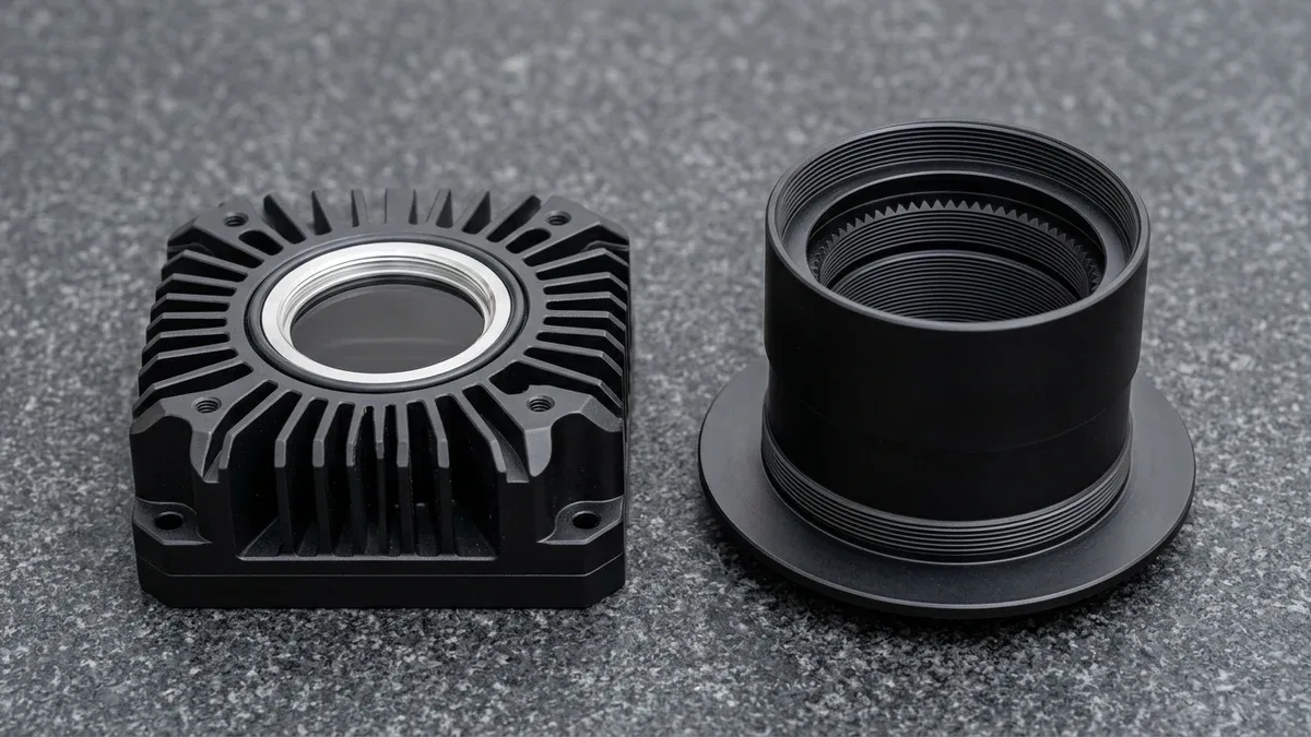
In outdoor perimeter surveillance, thermal imaging, and pan-tilt-zoom (PTZ) gimbals, optical resolving power depends directly on mechanical datum stability. Executing precision imaging devices manufacturing requires simultaneous control of barrel concentricity, fine-pitch thread tolerances, stray-light absorption, and enclosure sealing. Through specialized security camera housing CNC machining and optical lens barrel machining, hardware teams eliminate focal plane tilt and moisture ingress.
From an optomechanical standpoint, a 0.025 mm (0.0010″) axial runout or angular tilt across a Complementary Metal-Oxide-Semiconductor (CMOS) or Charge-Coupled Device (CCD) image sensor seat shifts edge pixels outside the lens depth of focus. Furthermore, uncompensated anodic oxide growth on fine M0.5 focusing threads causes aluminum galling, while deep cuts in die-cast shells expose subsurface porosity.
At our in-house precision manufacturing facility, AS Prototypes integrates live-tool CNC turning and mill-turn centers, high-speed 3-axis and 4-axis Vertical Machining Centers (VMCs), and temperature-stabilized Zeiss Coordinate Measuring Machine (CMM) metrology. Below, we detail the datum stack-ups, M0.5 threading rules, anodizing offsets, and IP67 sealing protocols.
Executive Summary & Engineering Takeaways (BLUF)
- Single-Setup Optical Datum Control: CNC mill-turn machining of 6061-T6 and 7075-T651 barrels holds H7 lens-seat bore concentricity within ⌀0.010 mm (0.0004″) and CMOS/CCD sensor pad perpendicularity within ⊥ 0.010 mm (linear mating features ±0.010 to ±0.020 mm; general tolerances ISO 2768-mK).
- Fine M0.5 Threads & Light Baffles: Single-point carbide threading cuts burr-free M12×0.5 (S-mount), M28×0.5, and 1″-32 UN (C-mount) threads alongside 30°–45° sawtooth light-baffle grooves, finished with #220 glass-bead blasting (Ra 1.2 to 1.6 µm) and MIL-A-8625 Type II Class 2 matte black anodizing (8 to 15 µm).
- Pre-Anodize Pitch Diameter Offsets: Machinists pre-offset 60° fine thread pitch diameters by 2.0 × tanodize (0.016 to 0.030 mm diametral allowance for 8 to 15 µm coatings, or 1.0 × tanodize on unmasked H7 bores) and avoid thick 25–50 µm Type III hardcoat on M0.5 threads to prevent binding.
- Billet vs. Die-Cast IP67 Enclosures: High-speed 3-axis and 4-axis VMCs machine billet 6061-T6 housings for 10 to 300 units, while high-volume ADC12 / A380 die-cast PTZ dome bases restrict AS568 O-ring gland skim cuts to 0.25 to 0.35 mm to preserve the 0.30–0.50 mm dense chill skin.
- Ex-Factory Turnaround: Design for Manufacturability (DFM) quotes return within 24 hours, bare CNC prototypes in 4 to 8 business days, matte black anodized barrels in 7 to 12 business days, and die-cast tooling with T1 samples in 18 to 35 business days (Ex-Factory Turnaround, excluding 3 to 5 business days air transit).
Article Engineering Navigation
- 1. Optical Datum Stack-Up in Imaging Devices Manufacturing: Barrels & Sensor Seats
- 2. Single-Point Threading M0.5 Optical Mounts & Stray-Light Baffle Grooves
- 3. Why Do Fine M0.5 Camera Lens Threads Seize After Matte Black Anodizing?
- 4. Material Selection & Limitations for Security Camera Housings & Optical Mounts
- 5. Billet CNC Milling vs. Post-Machined A380 Die-Cast PTZ Housings for IP67 Sealing
- 6. Zeiss CMM Metrology, Optical VMS Thread Verification & Ex-Factory Lead-Time Benchmarks
- 7. Technical Engineering FAQ
1. Optical Datum Stack-Up in Imaging Devices Manufacturing: Barrels & Sensor Seats
Optomechanical datum architecture in imaging devices manufacturing links objective lens seats, focusing helicoids, and the rear sensor plane within a ⌀0.010 mm (0.0004″) coaxial zone and ±0.010 mm (±0.0004″) flange focal distance (FFD). While general housing features follow ISO 2768-mK limits, zoom and thermal barrels suffer severe coma whenever bore coaxiality drifts beyond 0.015 mm.
To prevent optical decentering, our engineers structure Geometric Dimensioning and Tolerancing (GD&T) per ASME Y14.5 around three functional datums (shown in the cross-section schematic below). The optical axis aligns stepped H7 (+0.021 / 0 mm for ⌀18–30 mm) lens seats within ⌀0.010 mm concentricity, M0.5 threads, the IP67 O-ring gland, and the CMOS pad within ⊥ 0.010 mm.
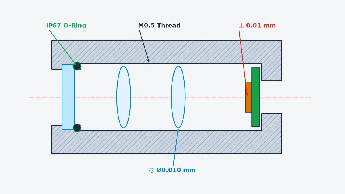
Splitting a thin-walled 6061-T6 or 7075-T651 barrel between a 2-axis lathe and vertical mill introduces 0.015 to 0.030 mm of Total Indicator Reading (TIR) re-clamping runout. In our in-house shop, live-tool CNC mill-turn centers turn H7 lens seats and M28×0.5 threads, then C-axis mill rear CMOS PCB bosses and ⌀2.000 mm H7 dowel holes in one setup.
To prevent trilobal chuck distortion on thin 1.0 to 1.5 mm barrel walls, we grip workpieces in 360° full-contact contoured aluminum pie soft jaws (contoured pie jaws) at 0.8 to 1.2 MPa drawbar pressure. Rough-machined 6061-T6 blanks undergo intermediate stress-relief annealing at 150–165°C (302–329°F) before finish boring to hold circularity within ○ 0.005 mm.
2. Single-Point Threading M0.5 Optical Mounts & Stray-Light Baffle Grooves
Single-point CNC optical threading cuts ultra-fine M0.5 to M0.75 metric (M12×0.5 S-mount, M28×0.5) and 1″-32 UN (C-mount) threads to ISO 965 6H/6g fits at Ra 0.8 µm (32 µin). Using solid-carbide boring bars with PVD carbide inserts (rε ≤ 0.05 mm) at Vc = 150 m/min with 29.5° flank infeed across 8–12 passes eliminates crest burrs.
Behind the lens seats, grazing off-axis light reflecting off smooth aluminum walls causes flare on high-dynamic-range (HDR) sensors. As shown in the wire-EDM sectioned 6061-T6 barrel cutaway below, we turn concentric 30° to 45° sawtooth micro-baffle grooves (0.35 mm pitch, 0.25 mm depth) along internal bores before executing our three-step optical matte black anodizing sequence:
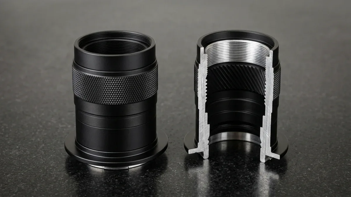
- Micro-Bead Texturing (#220 Glass Media): Internal baffles are blasted at 0.25 MPa while H7 lens seats are masked with POM plugs, yielding a diffusive Ra 1.2 to 1.6 µm (47 to 63 µin) matte finish.
- MIL-A-8625 Type II Class 2 Matte Black Anodizing: Sulfuric acid anodizing at 20°C grows an 8 to 15 µm nanoporous film dyed deep black, cutting specular reflectivity below 1.5% across 400–940 nm wavelengths.
- Ultrasonic Blind-Hole Flushing: Dual-frequency 40/80 kHz ultrasonic cleaning expels glass beads and chemical salts from M1.6–M2.5 blind sensor mounting holes.
| Optical Mount Standard | Thread Designation & Fit | Single-Point Pass Schedule | Pre-Anodize Pitch Offset (t = 12 µm) | Primary Camera Application |
|---|---|---|---|---|
| S-Mount (Board Lens) | M12×0.5 — ISO 965 6H / 6g | 8 Passes (29.5° Flank, rε = 0.04 mm) | +0.024 mm (6H ID) / -0.024 mm (6g OD) | Compact IP dome cameras and UAV gimbal boards. |
| C-Mount / CS-Mount | 1″-32 UN — ASME B1.1 2B / 2A | 10 Passes (29.5° Flank, rε = 0.05 mm) | +0.024 mm (2B ID) / -0.024 mm (2A OD) | Box surveillance cameras (17.526 mm / 12.526 mm FFD). |
| Medium Zoom Barrel | M28×0.5 / M42×0.75 — 6H / 6g | 10–12 Passes + 1 Spring Skim Pass | +0.024 mm (6H ID) / -0.024 mm (6g OD) | Motorized varifocal PTZ and traffic ANPR barrels. |
| Telephoto / LWIR Barrel | M58×0.75 / M72×0.75 — 6H / 6g | 12 Passes (Anti-Vibe Carbide Bar) | +0.024 mm (6H ID) / -0.024 mm (6g OD) | Long-range germanium thermal and border PTZ optics. |
3. Why Do Fine M0.5 Camera Lens Threads Seize After Matte Black Anodizing?
Fine M0.5 and M0.75 optical threads seize after anodizing because aluminum oxide (Al2O3) grows 50% inward and 50% outward, and 60° thread flanks (1/sin 30° = 2.0×) produce a net pitch-diameter shift of ΔD2 = 2.0 × tanodize. Because an M0.5-6H/6g fit has 0.020 mm pitch clearance, an uncompensated 12–15 µm coating creates 0.024–0.030 mm interference.
Specifying MIL-A-8625 Type III hardcoat (25 to 50 µm) on unmasked M0.5 threads creates up to 0.100 mm pitch-diameter interference and brittle crest spalling that contaminates CMOS sensors. Instead, we apply 8–15 µm Type II Class 2 matte black anodizing, pre-offsetting thread pitch diameters by 0.016–0.030 mm and unmasked H7 bores by 0.008–0.015 mm.
📐 Shop-Floor Optomechanical Calculations: Sensor Tilt Blur, Thread Offset & Thermal Rise
1. Depth of Focus & Tilt Defocus:
At f/1.4 (N=1.4, c=0.0029 mm), DoF = ±2·N·c = ±0.0081 mm (8.1 µm axial window; Airy ±2·λ·N2 = ±2.16 µm). For sensor diagonal Ldiag=11.0 mm at tilt θ=0.08°, edge defocus Δz = (Ldiag/2)·tan θ = 5.5 × 0.001396 = 0.0077 mm, requiring ⊥ 0.010 mm datum control.
2. Pre-Anodize 60° Metric Thread Pitch Offset:
With outward oxide buildup Δrn = 0.5·tanodize per 60° flank (sin 30° = 0.5), pitch diameter shifts by D2,machined = D2,nominal ± 2.0·tanodize. At tanodize = 12 µm, internal M28×0.5-6H bores oversize by +0.024 mm, external M28×0.5-6g turns undersize by -0.024 mm, and unmasked H7 bores oversize by +0.012 mm.
3. Steady-State Thermal Resistance (6061-T6 vs. ADC12):
From ΔT = QLED · Rθ at QLED = 18 W (IR-LED + PoE+ load), die-cast ADC12 (Rθ = 2.2 K/W) reaches ΔT = 39.6°C, whereas CNC-finned 6061-T6 (Rθ = 1.15 K/W) reaches ΔT = 20.7°C—a -18.9°C reduction that cuts CMOS dark-current noise.
When tactical or marine PTZ housings mandate MIL-A-8625 Type III Class 2 hard anodizing (25 to 50 µm) on exterior wear surfaces, we seal M0.5 threads and H7 bearing bores with custom-turned EPDM or high-temperature silicone masking plugs, then selectively apply Type II Class 2 matte black (8 to 15 µm) to internal optical paths.
4. Material Selection & Limitations for Security Camera Housings & Optical Mounts
Selecting alloys for security imaging hardware requires balancing thermal conductivity for Power-over-Ethernet (PoE+) heat dissipation, specific stiffness (E/ρ) for PTZ gimbals, and anodizing response. While wrought 6061-T6 and 7075-T651 dominate optical barrels, engineers must account for three critical material limitations:
- When to Avoid 7075-T651 Aluminum: Despite 503 MPa yield strength for thin-wall zoom helicoids and gimbal yokes, 7075-T651 is non-weldable, susceptible to marine stress-corrosion cracking (SCC), and must never exceed 100–110°C (212–230°F) during baking to prevent over-aging.
- When to Avoid Die-Cast ADC12 / A380 for Optical Barrels: High silicon content (7.5%–12% Si, raw casting tolerance ISO 8062 CT4–CT6) forms gray-brown smut during sulfuric acid anodizing and cannot hold crisp M0.5 threads. Internal barrels must be turned from wrought 6061-T6 bar, while A380 outer shells use SurTec 650 / MIL-DTL-5541 conversion and 60–90 µm UV-resistant TGIC polyester powder coating.
- When to Avoid Unfilled Nylon Near Sensors: Unfilled PA6 absorbs up to 2.5% moisture and swells; specify CNC-turned POM-C or PEEK (±0.020 mm) for low-friction focus sleeves and thermal detector standoffs.
For long-wave infrared (LWIR, 8–14 µm) thermal security cameras using single-point diamond-turned (SPDT) germanium (Ge), zinc selenide (ZnSe), or chalcogenide optics, aluminum’s higher thermal expansion (CTE = 23.1 × 10⁻⁶ /K vs. 6.1 × 10⁻⁶ /K for Ge) requires precision-turned radial clearance pockets and wave-spring retainers to prevent lens pinching from -40°C to +70°C.
| Material Grade | Yield & Thermal Cond. | Machining Process | Critical Tolerance | Surface Finish | Recommended Application |
|---|---|---|---|---|---|
| 6061-T6 Billet | 276 MPa / 167 W/(m·K) | CNC Mill-Turn & 3/4-Axis VMC | Concentricity: ⌀0.010 mm | #220 Blast + Type II Matte Black (8–15 µm) | M0.5 optical lens barrels, CMOS mounts, and low-volume IP67 housings. |
| 7075-T651 Bar | 503 MPa / 130 W/(m·K) | CNC Mill-Turn & 4-Axis VMC | Datum: ⊥ 0.010 mm | Type III Hardcoat (mask M0.5 threads) | High-stiffness PTZ gimbal yokes and zoom cam helicoids. |
| ADC12 / A380 Cast | 160 MPa / 100 W/(m·K) | Die Cast + 3/4-Axis VMC Skim | CNC Seat: ±0.015 mm | MIL-DTL-5541 + 60–90 µm TGIC Powder | High-volume (500–10,000+) outdoor PTZ dome and bullet housings. |
| 316L Stainless | 205 MPa / 16.3 W/(m·K) | CNC Turning & 3/4-Axis VMC | Seal Gland: ±0.015 mm | ASTM A967 Passivation + Electropolish | Explosion-proof petrochemical and offshore marine camera shells. |
5. Billet CNC Milling vs. Post-Machined A380 Die-Cast PTZ Housings for IP67 Sealing
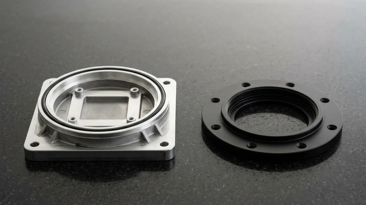
In our machine shop, 75% to 85% of camera enclosures and PTZ bases run on high-speed 3-axis and 4-axis VMCs (reserving 5-axis milling for complex airborne gimbals). Billet 6061-T6 suits 10 to 300 units with zero mold NRE, whereas post-machined ADC12/A380 die casting (shown below alongside its mating 6061-T6 lens bezel) drives economy above 500 units.
- Symptom (IP67 Pressure-Decay Leak): Post-machined ADC12 / A380 camera housings leak bubbles during 3.5 to 6.0 bar pressure-decay air leak testing or 1.0 m water immersion despite holding AS568 O-ring groove depth within ±0.020 mm.
- Root Cause (Breaching the Cast Chill Skin): Die castings solidify with a dense, pore-free outer chill skin only 0.30 to 0.50 mm thick. Milling deeper than 0.50 mm exposes internal gas pores (⌀0.15 to 0.40 mm) beneath the compressed 18%–25% silicone or EPDM O-ring.
- Corrective Action (0.25 to 0.35 mm Skim Cuts): We pre-core the O-ring groove in the H13 die-cast mold and restrict 3/4-axis VMC finishing to a 0.25 to 0.35 mm skim cut (Ra 0.8 to 1.6 µm) so the cutter stays inside the dense chill skin, adding MIL-I-17563C vacuum resin impregnation for IP68 units.
For front gorilla-glass or germanium window seals, we machine AS568 face-seal glands to provide 18% to 25% compression squeeze on 70 Shore A silicone or EPDM O-rings with a 70% to 80% gland fill ratio. Continuous contour milling eliminates radial cutter exit witness marks across the sealing land.
| Parameter | Billet 6061-T6 CNC Milling (3/4-Axis VMC) | ADC12 / A380 Die Casting + CNC Skim Cuts | Selection Rule |
|---|---|---|---|
| Batch Volume | 1 to 300 Units (Zero Dedicated Tooling NRE) | 500 to 10,000+ Units (Volume-Driven Economy) | Billet for EVT/DVT; die casting for mass production. |
| IP67 O-Ring Gland | Pore-Free Wrought Metal at Any Depth (Ra ≤ 0.8 µm) | Pre-Cored Gland + 0.25 to 0.35 mm Skim Cut | Preserve 0.30–0.50 mm chill skin; impregnate for IP68. |
| CMOS & Bore Fit | ±0.010 mm (±0.0004″) via Soft-Jaw VMC Setup | ±0.010 to ±0.020 mm via Hydraulic VMC Fixture | Both hold ⊥ 0.010 mm CMOS pad perpendicularity. |
| Ex-Factory Lead Time | 4–8 Business Days (Bare) / 7–12 Days (Anodized) | 18 to 35 Business Days (H13 Mold & T1 Samples) | Bridge pilot builds with CNC billet during mold build. |
6. Zeiss CMM Metrology, Optical VMS Thread Verification & Ex-Factory Lead-Time Benchmarks
Inside our 20°C ± 1°C metrology room, our Zeiss bridge CMM (available upon request) verifies H7 bore concentricity (⌀0.010 mm) and CMOS pad perpendicularity (⊥ 0.010 mm). Concurrently, our 2.5D Optical Video Measuring System (VMS) inspects 30°–45° baffle teeth, calibrated ISO 1502 Go/No-Go plug gauges check M0.5 threads, and 3.5–6.0 bar pressure-decay rigs validate IP67 sealing.
Every security imaging shipment includes a comprehensive First Article Inspection (FAI) package containing Zeiss CMM coaxiality and perpendicularity reports, ISO 4287 contact stylus profilometer traces (Ra / Rz) on O-ring glands, ISO 2360 eddy-current anodic film thickness logs (8 to 15 µm), and serialized 3.5 to 6.0 bar pressure-decay leak test records.
All production schedules below represent Ex-Factory Production & Inspection Turnaround from our in-house manufacturing facility (incorporating a mandatory 3-business-day quality inspection and surface-finish verification buffer), and are strictly separate from 3 to 5 business days of international DHL, FedEx, or UPS air freight transit:
- DFM & Quote: Within 24 hours (24 to 48 hours for die-cast tooling).
- As-Machined CNC Prototypes: 4 to 8 business days ex-factory.
- Matte Black Anodized (MIL-A-8625 Type II) or Powder-Coated Parts: 7 to 12 business days ex-factory.
- Low-to-Mid Volume Production (10 to 1,000+ Units): 7 to 30 business days ex-factory.
- Rapid ADC12 / A380 Die-Casting Tooling & T1 Samples: 18 to 35 business days ex-factory.
🔗 Related Optomechanical & Precision CNC Engineering Guides
- Optical & Industrial Lighting Hardware Manufacturing — Precision heatsink housings, optical barrels, and outdoor IP67 sealed assemblies.
- Optical Precision Machining & Diamond Turning Guide — Datum alignment, concentricity control, and ultra-fine optical mount machining.
- Aluminum Anodizing Cost & Specification Guide — MIL-A-8625 Type II matte black vs. Type III hardcoat film growth and thread allowances.
- High-Pressure Die Casting Process & DFM Guide — Managing ADC12/A380 chill skin thickness, porosity control, and CNC post-machining.
7. Technical Engineering FAQ
We specify MIL-A-8625 Type II Class 2 matte black anodizing at 8 to 15 µm thickness and pre-offset machined thread pitch diameters by 0.016 to 0.030 mm. We also avoid 25 to 50 µm Type III hardcoat on M0.5 threads to prevent flank interference and oxide flaking.
By turning and milling in one setup on our live-tool CNC mill-turn centers, we hold lens-seat bore concentricity within ⌀0.010 mm (0.0004″) and CMOS datum perpendicularity within ⊥ 0.010 mm. Critical linear mating features are held to ±0.010 to ±0.020 mm with general dimensions to ISO 2768-mK.
Milling deeper than 0.50 mm into an A380 die-cast boss cuts through the dense 0.30–0.50 mm chill skin and exposes subsurface porosity beneath the O-ring. We pre-core the gland in the mold and restrict CNC finishing to a 0.25–0.35 mm skim cut at Ra 0.8 µm.
We single-point turn concentric 30° to 45° sawtooth micro-baffle grooves along the internal optical bore and texturize the surface with #220 glass beads (Ra 1.2 to 1.6 µm). Subsequent MIL-A-8625 Type II Class 2 matte black anodizing reduces internal specular light reflectivity below 1.5%.
Ready to Manufacture Precision Security Camera Barrels & IP67 Housings?
Upload your 3D CAD models (STEP/IGES) and 2D tolerance drawings for a comprehensive optomechanical DFM review, pre-anodize M0.5 thread pitch-diameter offset calculation, and custom CNC turning, 3/4-axis milling, or A380 die-casting production quotation directly from our in-house engineering team.
Request an Optomechanical DFM Review & Custom Quote →