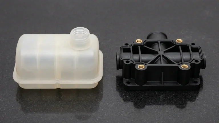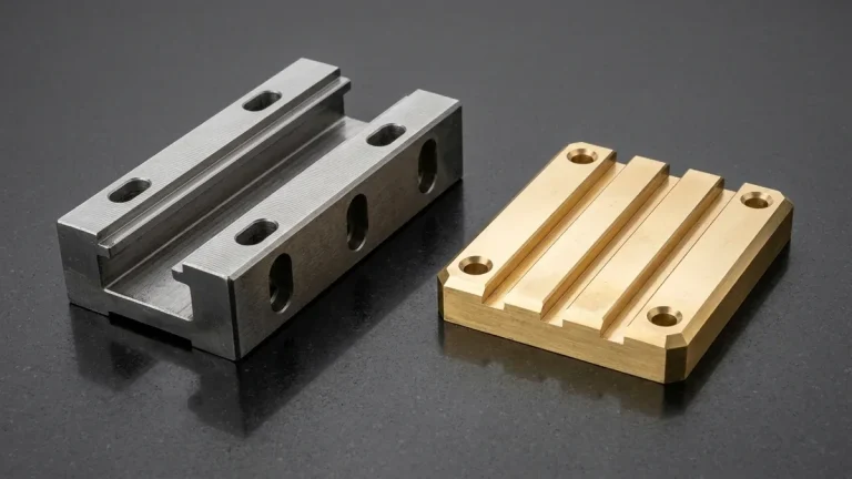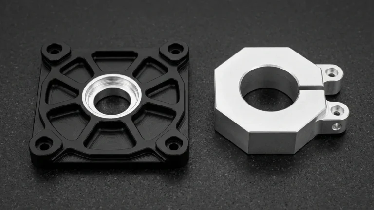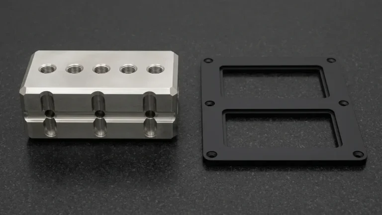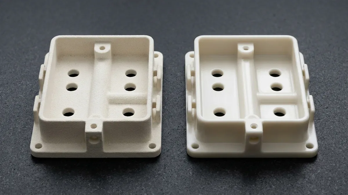
Additive manufacturing delivers remarkable geometric freedom directly from digital CAD files. However, as-printed parts frequently display staircase layer lines and inherent surface porosity. Applying professional 3D printing surface finishing techniques transforms raw builds into production-grade end-use parts.
Post-processing objectives vary across functional and aesthetic domains. For example, consumer electronics require Class-A cosmetic gloss and tactile smoothness. In contrast, aerospace fluid manifolds demand sealed, low-friction internal passages to optimize airflow.
At AS Prototypes, our 3D printing services integrate precision post-processing cells. Furthermore, our specialized surface finishing options provide tight mechanical tolerances and durable cosmetic coatings.
1. Core Mechanical and Chemical Finishing Processes
Engineers can choose between abrasive mechanical smoothing and automated chemical vapor treatments.
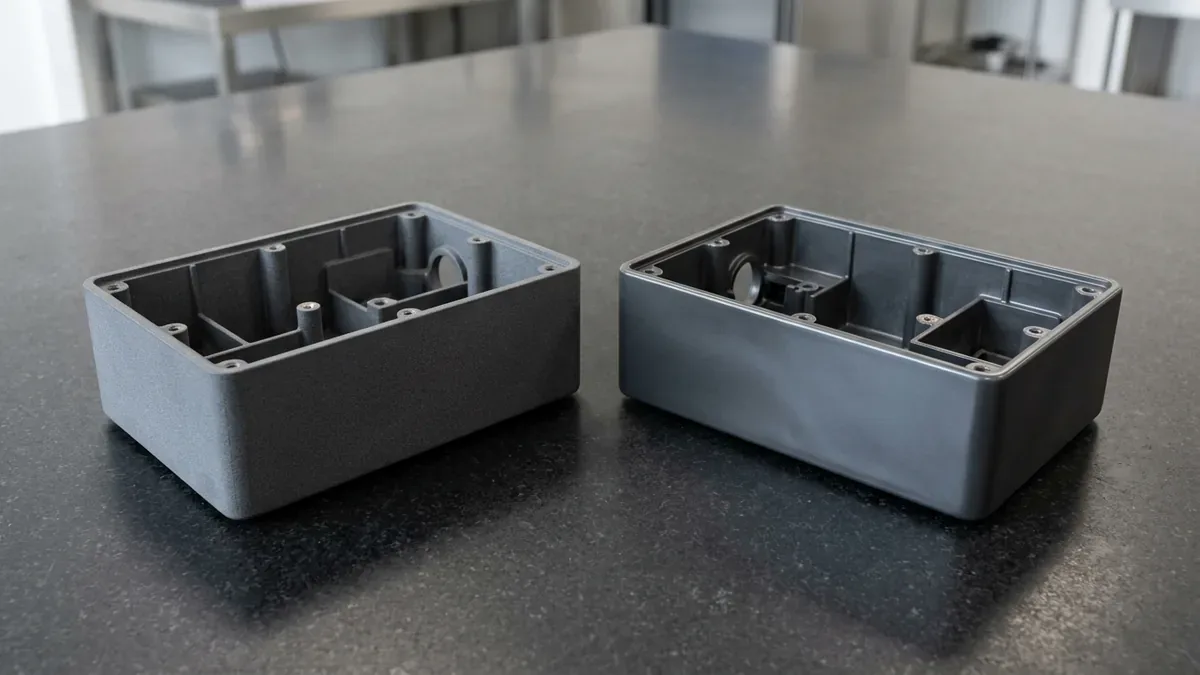
First, bead blasting uses pressurized glass or ceramic media. The media impacts the component at controlled velocities, peening the exterior surface. Consequently, bead blasting creates an attractive uniform satin matte finish while concealing layer textures.
Second, chemical vapor smoothing represents the gold standard for thermoplastic 3D-printed polymers (such as SLS/MJF PA12, PA11, TPU, and FDM ABS). Technicians suspend thermoplastic parts inside a sealed condensation chamber where vaporized solvent briefly reflows micro-ridges on external and internal walls, achieving water-tight sealing and injection-molded surface quality. Note that cross-linked thermoset SLA/DLP photopolymer resins cannot be solvent vapor-polished; optical clarity on SLA parts requires progressive wet sanding (#400 to #2000 grit) followed by a UV-resistant clear acrylic topcoat.
Third, vibratory tumbling deburrs and polishes high-mix batches economically. Ceramic or synthetic tumbling media smooths exterior edges over several hours. Thus, tumbling excels for robust SLS nylon and DMLS metal hardware.
| Finishing Process | Typical Roughness (Ra) | Dimensional Stock Removal | Compatible AM Technologies | Primary Engineering Advantage |
|---|---|---|---|---|
| As-Printed (Standard) | Ra 6.3 – 12.5 μm | Baseline (0 μm) | SLS, MJF, DMLS, FDM | Zero additional post-processing cost |
| Bead Blasting | Ra 3.2 – 6.3 μm | < 5 μm uniform | SLS, SLA, DMLS, MJF | Removes loose powder and creates uniform matte texture |
| Vapor Smoothing | Ra 0.8 – 1.6 μm | Negligible (redistributes resin) | SLS PA11/PA12, TPU, MJF | Seals internal pores and eliminates bacterial traps |
| Vibratory Tumbling | Ra 1.6 – 3.2 μm | 10 – 25 μm loss | SLS, DMLS, MJF | Cost-effective bulk radius blending and deburring |
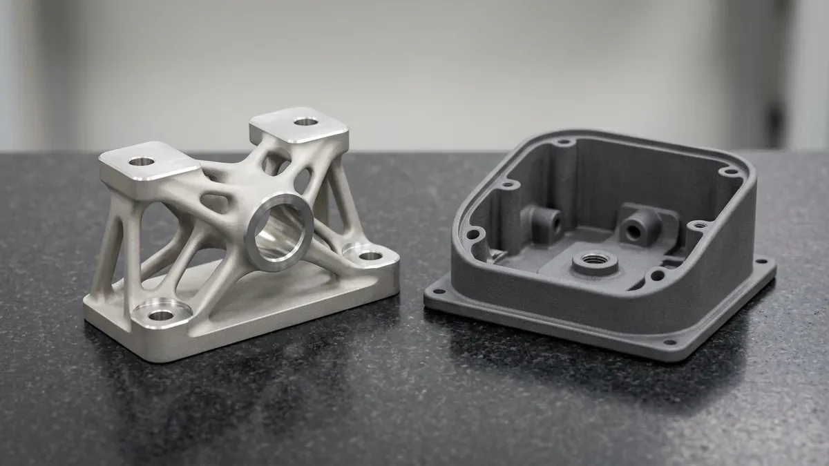
| CNC Post-Machining | Ra 0.4 – 0.8 μm | 0.5 – 1.5 mm allowance | DMLS Titanium, Inconel, AlSi10Mg | Holds bearing fits and tight ±0.010 mm (±0.0004″) mating tolerances and ISO 2768-mK general standards |
2. Secondary Machining and Coating Solutions
For high-performance metal components, additive fabrication alone rarely satisfies precision assembly datums. Therefore, engineers specify hybrid manufacturing workflows.
Specifically, designers leave sacrificial machining allowances on bearing bores, O-ring grooves, and flange mating faces. Afterward, precision multi-axis CNC mills face those datums down to exact drawing callouts. Consequently, parts combine additive lightweighting with CNC precision.
Additionally, functional coatings expand mechanical utility. For instance, electroplating plastic prototypes with copper and nickel provides electromagnetic shielding (EMI). Meanwhile, hard anodizing DMLS aluminum parts provides superior wear resistance in abrasive hydraulic systems.
| AM Technology | Recommended Surface Treatment | Achievable Target Specification |
|---|---|---|
| SLA Photopolymers | Wet sanding (#400–#2000), UV clear acrylic coat, automotive paint | Optical transparency or high-gloss show model finish (never vapor-polished) |
| SLS & MJF Nylon | Black immersion dyeing + chemical vapor smoothing | Satin black, sealed against oil and moisture absorption |
| DMLS / SLM Metals | Stress-relief heat treatment + CNC machining + passivation | H7 bore tolerances, ±0.010 mm (±0.0004″) true position datums |
| FDM / FFF Plastics | Acetone vapor smoothing (ABS) or high-build primer | Smooth exterior with zero visible layer seam lines |
3. Design for Post-Processing Guidelines
Engineers can significantly simplify finishing operations by implementing proactive DFM principles:
First, allocate adequate machining stock on critical surfaces. Model an extra one millimeter of stock on faces intended for CNC finishing.
Second, avoid blind deep recesses that trap tumbling media. Ensure that drainage holes allow thorough solvent evacuation during vapor smoothing.
Third, specify realistic surface roughness callouts. Over-specifying mirror finishes on non-critical faces escalates manufacturing cycle times unnecessarily.
4. Technical Engineering FAQ
No, controlled chemical vapor smoothing on thermoplastic SLS/MJF PA12 and ABS parts actually enhances tensile elongation by sealing microscopic surface pores and mitigating notch sensitivity (note that thermoset SLA photopolymer resins cannot undergo solvent vapor smoothing and require #400–#2000 wet sanding plus UV clear acrylic coating).
Bead blasting typically removes less than 5 microns of surface material. It primarily redistributes surface peaks without impacting critical overall part dimensions.
While threads can be printed, secondary CNC tapping delivers superior thread engagement. Consequently, tapped holes provide higher accuracy and pullout strength.
Accelerate Hardware Validation with Industrial 3D Printing & Hybrid CNC
Bridge additive design freedom with precision CNC datum finishing and polyurethane vacuum casting. Upload your 3D CAD assemblies (STEP/IGES/STL) to evaluate material selection, functional tolerances, and batch unit economics.
Request an Additive & Prototyping DFM Analysis