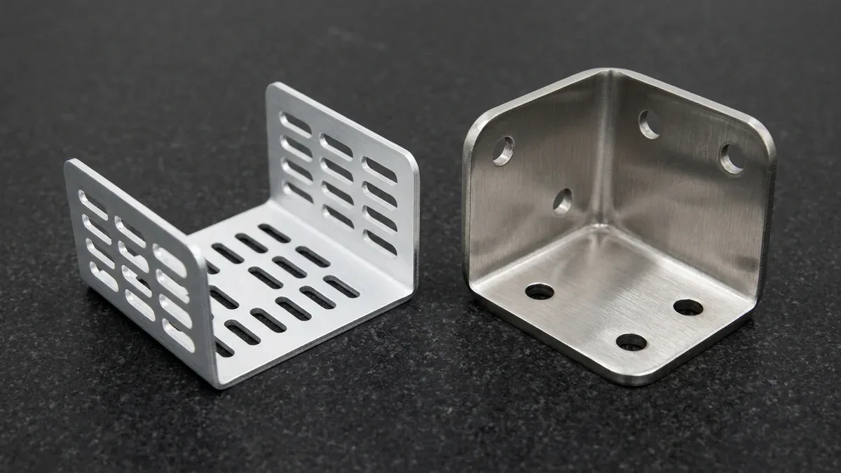
Accurate quotation and budget forecasting are vital for hardware product development. Therefore, mastering precision sheet metal cost calculation enables engineering teams to optimize component geometry and production volumes effectively. Unlike monolithic machining from thick billets, sheet metal fabrication involves a multi-stage manufacturing sequence. Raw sheet stock undergoes laser cutting, deburring, CNC press brake forming, hardware insertion, and surface coating.
Furthermore, each discrete manufacturing phase contributes distinct fixed setup charges and recurring variable cycle expenses. In this engineering guide, we break down primary cost components across materials, machine runtimes, and labor. In shop-floor practice, we provide actionable DFM recommendations to minimize fabrication expenses.
By AS Prototypes Engineering Team — Senior Sheet Metal Fabrication Specialist (12+ Years Shop-Floor Experience) | Last Updated: October 2026
Executive Summary & Engineering Takeaways (BLUF)
- Four-Component Cost Equation: Custom sheet metal unit cost equals Raw Sheet Blank Allocation (including scrap skeleton) + Fiber Laser Cutting Time (perimeter + pierce count) + CNC Press Brake Setup & Stroke Labor + Secondary Hardware Insertion (PEM), Welding & Finishing.
- Sheet Utilization & Dynamic Nesting: Standard coils and mill sheets measure 1,220 × 2,440 mm (48″ × 96″) or 1,500 × 3,000 mm (60″ × 120″); designing interlocking L/U-brackets or splitting large welded frames boosts nesting utilization from 52% to >78%, cutting raw material cost by up to 30%.
- Press Brake Tooling Standardization: Each distinct V-die or gooseneck punch setup requires 15 to 25 minutes of press brake changeover; standardizing all internal bend radii across a part to ri = 1.0 × t (1× material thickness) allows continuous single-setup bending.
- Standard Gauge & Hole-to-Bend DFM: Selecting stocked Pearl River Delta gauges—SPCC/304/5052 in 1.0, 1.2, 1.5, 2.0, 2.5, or 3.0 mm (20, 18, 16, 14, 12, or 11 Ga)—and keeping holes at least 2.0t + ri away from bend lines eliminates secondary post-bend re-drilling.
Article Engineering Navigation
- 1. The Four Core Cost Drivers in Sheet Metal Fabrication
- 2. Material Utilization and CAM Dynamic Nesting Physics
- 3. Press Brake Tooling Setups and Forming Cycle Costs
- 4. Precision DFM Rules for Cost Reduction
- 5. Quantitative Sheet Metal Cost Formulation & Nesting Yield Math
- 6. Why Do Custom Sheet Metal Brackets Suffer Unexpected Cost Spikes?
- 7. Step-by-Step Sheet Metal Quotation & Production Workflow
- 8. Technical Engineering FAQ
1. The Four Core Cost Drivers in Sheet Metal Fabrication
Core Physical Principles and Shop-Floor Execution
Estimating custom sheet metal pricing requires evaluating four interconnected operational categories. First, raw material cost encompasses sheet alloy pricing, gauge thickness, and CAM nesting layout efficiency. Second, cutting machine runtime accounts for fiber laser piercing time, contour feed rates, and assist gas consumption.
Third, forming labor costs depend on total bend hits, specialized punch tooling setups, and manual workpiece repositioning. Finally, secondary operations include self-clinching hardware installation, TIG welding, and exterior cosmetic finishing. The breakdown table below summarizes relative cost percentages across standard production batches.
| Cost Component | Prototype Batch (1 to 20 pcs) | Mid-Volume Batch (100 to 500 pcs) | Production Batch (1,000+ pcs) | Primary Cost Driver |
|---|---|---|---|---|
| Raw Sheet Material | 15% to 25% | 35% to 50% | 50% to 65% | Alloy grade, thickness, nesting scrap ratio |
| Laser / Waterjet Cutting | 20% to 30% | 20% to 25% | 15% to 20% | Total linear cut length, assist gas choice |
| CNC Press Brake Bending | 25% to 35% | 15% to 20% | 10% to 15% | Number of bend lines, tooling setups |
| Hardware & Assembly | 10% to 15% | 10% to 15% | 8% to 12% | PEM clinch nut count, spot welding |
| Surface Finishing | 15% to 25% | 10% to 15% | 8% to 12% | Powder coating, anodizing, plating |
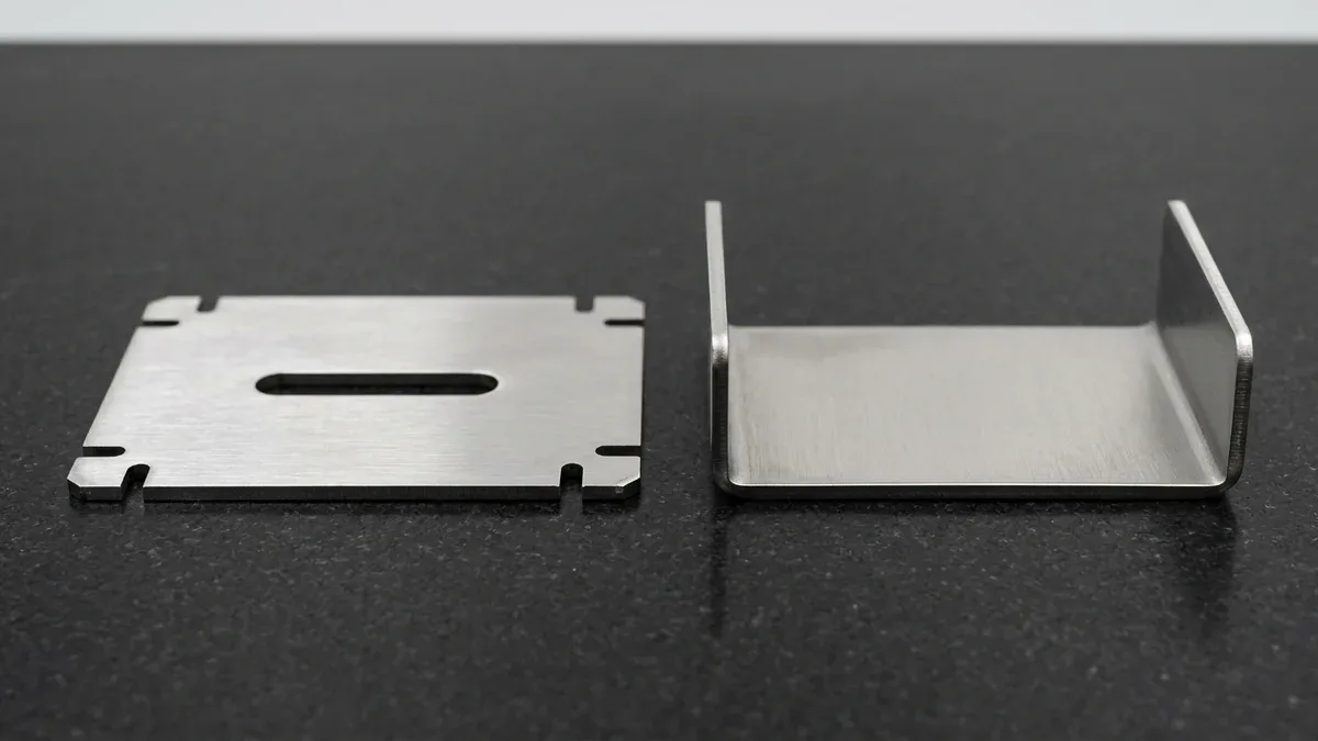
As seen in the 2.0 mm 304 stainless steel sheet metal flat-pattern blank and press-brake formed U-channel bracket resting side by side on the granite surface plate in Figure 1, high-pressure nitrogen fiber laser cutting produces oxide-free edges and pre-cut corner bend-relief notches that fold cleanly into concentric R2.0 mm inner and R4.0 mm outer 90-degree bends.
2. Material Utilization and CAM Dynamic Nesting Physics
Primary Process Capabilities and Equipment Architecture
Raw sheet metal pricing is calculated by weight and sheet area footprint. Standard commercial sheet formats measure 4×8 feet or 5×10 feet. When CAM software nests irregular blank geometries, unused skeleton webbing becomes scrap. Consequently, low nesting efficiency inflates effective per-part material costs significantly.
Therefore, engineers should design flat blank profiles that interlock neatly on common sheet dimensions. For example, common-line cutting allows adjacent parts to share a single laser cut path. Thus, common-line nesting reduces machine run time while increasing overall material utilization beyond 85 percent. Discover our full suite of precision sheet metal fabrication services to configure high-efficiency production runs.
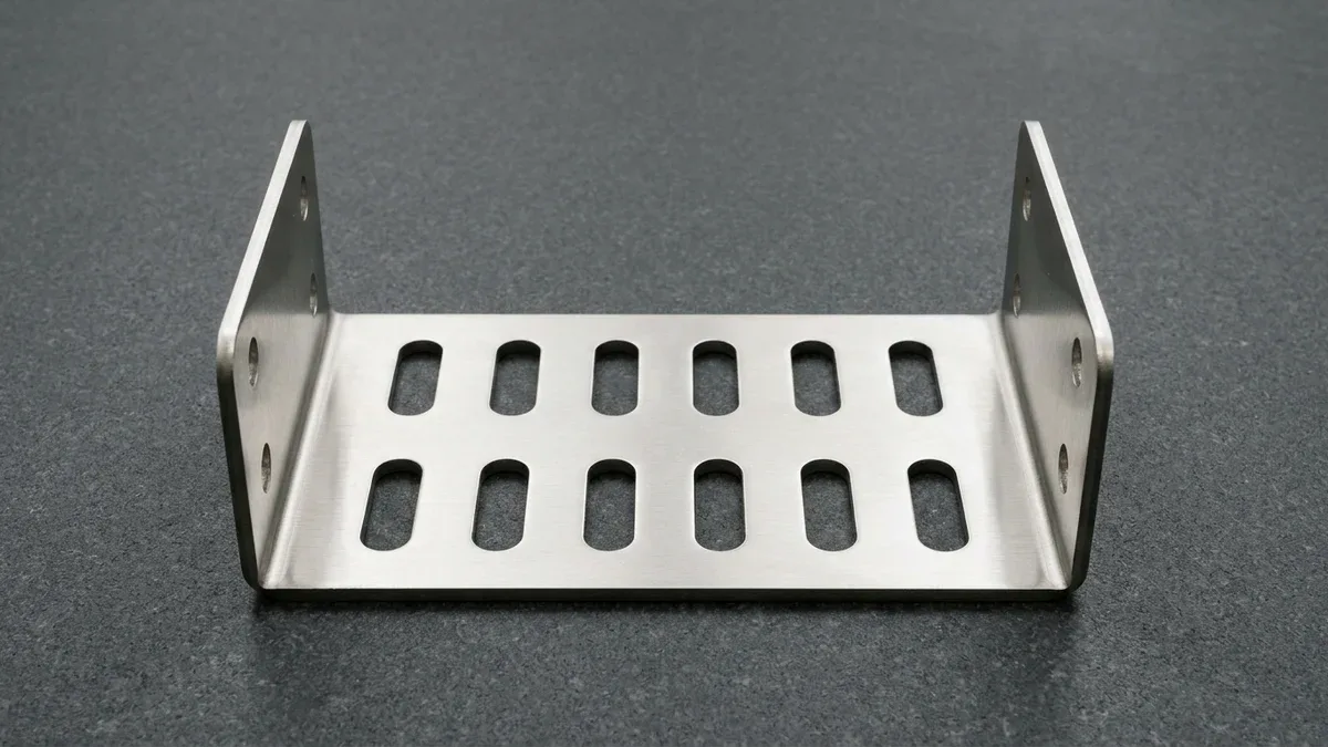
As shown in the press-brake formed 2.5 mm brushed 304 stainless steel U-channel structural mounting bracket resting flat on the granite surface plate in Figure 2, maintaining a hole-to-bend clearance of at least 2.5t + R prevents ovality distortion along the oblong base cooling slots while preserving a uniform 2.5 mm gauge across concentric R2.5 mm inner and R5.0 mm outer 90-degree bends.
3. Press Brake Tooling Setups and Forming Cycle Costs
Critical Process Parameters and Tooling Selection
Bending operations contribute significant manual labor and machine setup time. Each unique bend radius or flange orientation may require distinct upper punch and lower V-die tooling. When a design specifies multiple different bend radii, technicians must reconfigure machine tooling repeatedly.
Conversely, standardizing all internal bend radii across a part allows continuous single-setup forming. Furthermore, maintaining consistent flange heights enables high-speed automated backgauge indexing. In addition, design teams can review our protective metal surface finish options. Proper plating allowances ensure coatings do not compromise tight bend tolerances.
4. Precision DFM Rules for Cost Reduction
Practical Design-for-Manufacturing (DFM) Guidelines
Applying rigorous DFM principles early reduces sheet metal fabrication costs dramatically. First, avoid non-standard sheet thicknesses that require custom mill rolling orders. Instead, utilize standard commercial gauges in 5052-H32 aluminum, 304 stainless steel, or cold-rolled mild steel.
Second, ensure hole edges remain at least twice the material thickness away from bend tangent lines. Placing cutouts too close to bend lines causes hole distortion, necessitating expensive secondary reaming. Finally, replace complex welded corner joints with continuous stamped relief notches whenever possible.
5. Quantitative Sheet Metal Cost Formulation & Nesting Yield Math
Four-Variable Unit Cost Decomposition
To eliminate guesswork during early hardware budgeting, manufacturing engineers decompose custom sheet metal pricing into four deterministic physical variables: raw blank material allocation (including the skeleton web scrap), fiber laser cutting duration, CNC press brake forming labor, and secondary hardware/finishing operations. For a batch quantity of N identical enclosures or brackets, the total unit manufacturing cost (Cunit) is governed by the shop-floor cost equation:
Cunit = [ (Aflat · t · ρ · Pkg) / ηnest ] + [ (Lcut / vlaser + Npierce · tpierce) · Rlaser ] + [ (Tsetup / N + Nbends · tstroke) · Rbrake ] + CPEM_finish
where Aflat is the net unfolded flat-pattern area, t is sheet thickness, ρ is alloy density, ηnest is the sheet nesting utilization ratio (typically 0.55 to 0.82), Lcut is total laser perimeter path length, vlaser is cutting feed rate, Npierce is the number of internal cutouts plus outer lead-in pierces, and Nbends is the total press brake hit count.
DIN 6935 Bend Allowance (BA) and Bend Deduction (BD) Equations
Furthermore, to guarantee that the unfolded flat pattern nests accurately and bends to ±0.15 mm (±0.006″) flange tolerances on the first run without trial-and-error scrap, the flat blank length (Lflat) must account for the neutral-axis Bend Allowance (BA) and K-factor per DIN 6935:
BA = π · (θ / 180°) · (ri + K · t) | BD = 2 · (ri + t) · tan(θ / 2) − BA | Lflat = Louter_1 + Louter_2 − BD
Consider a concrete calculation for a 2.0 mm (14 Ga / 0.079″) 5052-H32 aluminum U-channel chassis bracket with two 90° bends, an internal bend radius of ri = 2.0 mm (1.0t), air-bent over a 16 mm (8t) V-die where K = 0.41: each 90° bend yields a Bend Allowance of BA = 3.1416 × 0.5 × (2.0 + 0.41 × 2.0) = 4.43 mm (0.174″) and an outside-flange Bend Deduction of BD = 2 × (2.0 + 2.0) × 1.0 − 4.43 = 3.57 mm (0.141″).
Standardizing both bends to ri = 2.0 mm allows the operator to form both flanges in one 18-second handling cycle on a single V-die station, whereas specifying one R1.0 mm bend and one R5.0 mm bend forces a second 20-minute press brake tooling setup that increases small-batch bending cost by 140%.
6. Why Do Custom Sheet Metal Brackets Suffer Unexpected Cost Spikes?
Eliminating Secondary Rework and Press Brake Changeover Penalties
Unexpected cost spikes in custom sheet metal fabrication are almost always triggered by non-standard mill sheet thicknesses, holes placed inside the plastic bend-deformation zone that require secondary CNC machining after bending, colliding return flanges that mandate custom gooseneck tooling, or excessive TIG seam welding where tab-and-slot spot welding would suffice. While fiber laser cutting itself takes only seconds per part, manual secondary rework and custom press brake setup labor can triple the final unit quotation.
The following engineering matrix details the five most common sheet metal cost multipliers encountered during DFM review and how to eliminate them in CAD:
| CAD Design Flaw / Symptom | Shop-Floor Manufacturing Penalty | Relative Cost Impact | Quantitative DFM Redesign Rule | Quality & Fit Benefit |
|---|---|---|---|---|
| Holes Placed Too Close to Bend Line | Circular holes stretch into teardrops during bending; requires slow post-bend VMC drilling or laser pilot + reaming | +25% to +45% unit cost | Keep hole edge distance ≥ 2.0t + ri from the inside bend tangent line (or add a 1.5t relief slot along the bend) | 100% flat-laser cut holes with zero ovality distortion |
| Short Flanges Below Minimum V-Die Span | Flange slips into the lower V-die opening (V = 6t–8t); requires sacrificial bridge tab laser-cutting and hand grinding | +30% to +50% labor cost | Maintain minimum external flange length bmin ≥ 4.0t + ri (e.g., ≥10 mm / 0.39″ on 2.0 mm / 14 Ga sheet) | Clean single-stroke air bending with ±0.5° angle repeatability |
| Non-Stock / Arbitrary Metric Thickness | Specifying 1.75 mm or 2.8 mm forces custom coil slitting, minimum mill order surcharges, or face-milling plate | +40% to +80% raw material cost | Select standard stocked gauges: 0.8, 1.0, 1.2, 1.5, 2.0, 2.5, 3.0, 4.0, 5.0, or 6.0 mm in SPCC, 304, or 5052-H32 | Immediate warehouse stock availability (4–8 business days) |
| Full-Length Continuous TIG Weld Seams | Continuous manual TIG welding warps 1.2–2.0 mm sheet from thermal input and requires hours of angle-grinder blending | +50% to +120% assembly cost | Use laser-cut self-fixturing tab-and-slot joints with intermittent stitch welds, hand-held fiber laser welds, or PEM studs | Eliminates weld jigs and prevents thermal box twisting |
| Tight Machining Tolerances (±0.02 mm) on Bends | Coil-to-coil thickness variation (±0.08 mm) and grain springback make ±0.02 mm flange-to-flange impossible by bending alone | +60% to +100% secondary CNC | Keep hole-to-hole within the same flat face (±0.10 mm / ±0.004″); allow DIN 6935 (±0.25–0.40 mm) across bend lines | Zero post-bend CNC fixture milling required |
Engineering Trade-Offs: Sheet Metal Fabrication vs. CNC Billet vs. Stamping
While laser-cut and press-brake-bent sheet metal is the most economical architecture for hollow enclosures, brackets, and server chassis between 1 and 2,500 units, engineers should transition to alternative processes under two conditions:
- When to Choose 3-Axis CNC Billet Milling Instead: If the component requires variable floor thicknesses, 3D contoured O-ring sealing grooves, pocketed heat-sink fins, or hole-to-hole true position tolerances of ±0.010 mm (±0.0004″) across orthogonal walls, CNC machining from solid 6061-T651 plate eliminates weld distortion and bend stack-up completely.
- When to Transition to Progressive Die Stamping: Once annual production volume for a small bracket or spring clip exceeds 15,000 to 50,000+ units and the CAD geometry is 100% frozen, investing in hardened D2/SKD11 progressive stamping dies (18 to 35 business days tooling turnaround) reduces piece-part cycle time from 45 seconds of laser/brake work to 0.5 seconds per press stroke.
7. Step-by-Step Sheet Metal Quotation & Production Workflow
Four-Stage Unfolding, Fiber Laser Nesting, and Press Brake Execution
To transform your 3D CAD assembly into burr-free, dimensionally verified sheet metal hardware with maximum cost efficiency, our sheet metal division executes a four-step engineering workflow:
- Step 1: Unfolding Validation & K-Factor Calibration — Engineers import your 3D STEP model, verify uniform wall thickness across all flanges, insert laser bend-relief notches (width ≥1.0t, depth ≥ri + t) at all three-plane corners, and generate flat DXF profiles calibrated to our press brake V-die tables.
- Step 2: Dynamic Multi-Part Sheet Nesting & N2/O2 Fiber Laser Cutting — CAM software nests parts across standard 1,220 × 2,440 mm (48″ × 96″) sheets using common-line cutting where permissible, cutting blanks on 6 kW–12 kW fiber lasers with high-pressure Nitrogen (N2) assist gas to produce oxide-free, weld-ready edges on 304 stainless and 5052 aluminum.
- Step 3: Wide-Belt Timesavers Deburring & CNC Press Brake Forming — Flat blanks pass through automated abrasive wide-belt deburring and edge-rounding machines before forming on multi-axis CNC press brakes equipped with optical laser angle measurement systems that compensate for coil springback in real time.
- Step 4: Haeger Hydraulic Hardware Insertion & Surface Finishing — Self-clinching PEM nuts, standoffs, and studs are pressed flush into laser-cut mounting holes under calibrated hydraulic tonnage (preventing sheet dimpling), followed by MIL-DTL-5541 chromate conversion, MIL-A-8625 anodizing, or electrostatic RAL powder coating.
🔗 Related Sheet Metal Fabrication, Laser Cutting & Bending Guides:
To optimize flat-pattern nesting yield and press brake tooling setups on custom enclosures, explore our custom sheet metal fabrication services and powder coating and anodizing finishes, or consult our engineering guides on Fiber Laser Cutting Assist Gases & Kerf DFM, Precision Sheet Metal Forming & K-Factor Rules, and Optimizing Sheet Metal Production Through Smart Design.
8. Technical Engineering FAQ
Fiber laser cutting time is calculated as Total Cut Path Length divided by Material Feed Speed (mm/min), plus Total Pierce Count multiplied by Pierce Dwell Time (0.2 to 1.5 seconds per pierce depending on plate thickness), plus rapid traverse overhead. Replacing a decorative 200-hole circular mesh grid with 20 elongated obround louver slots cuts pierce count by 90% and reduces laser machine time by 45%.
In air bending on a CNC press brake, the natural internal bend radius (ri) is determined primarily by the lower V-die opening width (typically V = 6t to 8t, yielding ri ≈ 1.0t to 1.25t). If a drawing calls out three different arbitrary bend radii (e.g., R0.5, R2.5, and R4.0 mm) on one 1.5 mm (16 Ga) bracket, the operator must stop and swap segmented V-dies three times, tripling setup NRE.
If a single monolithic flat pattern unfolds into an awkward cross or star shape that wastes 50% of the rectangular sheet metal blank—or creates deep colliding return flanges that require expensive custom horn punches—splitting the design into a simple U-channel base and a flat end-panel joined via PEM studs, blind rivets, or spot welds often reduces total unit cost by 20% to 35%.
In prototype batches of 1 to 10 units, fixed engineering CAM programming, laser bed loading, and press brake backgauge setup account for 55% to 70% of the unit price. Once batch quantities reach 100 to 1,000+ units, setup labor is amortized across the run, making raw sheet nesting efficiency (scrap ratio), PEM fastener count, and powder-coating rack density the dominant cost levers.
Ready to Validate Your CAD Design for Precision Manufacturing?
Upload your 3D CAD models (STEP, IGES, SolidWorks) and 2D engineering drawings for a comprehensive DFM engineering review and custom quotation from our in-house CNC machining and prototyping team.
Request a Custom DFM Review & Quote →