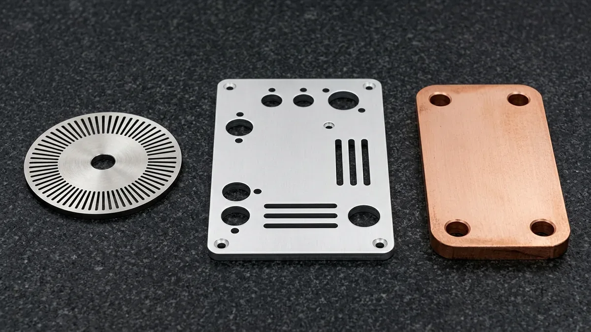
Industrial fabrication increasingly depends on rapid, accurate profile cutting of diverse engineering sheet metals. Therefore, deploying advanced CNC laser cutting provides design engineers with exceptional contouring versatility and rapid production turnaround. CNC laser cutting focuses a coherent, high-density photon beam through optical collimators onto flat sheet stock. Consequently, target material melts, burns, or vaporizes along precision computer-guided vector paths within seconds.
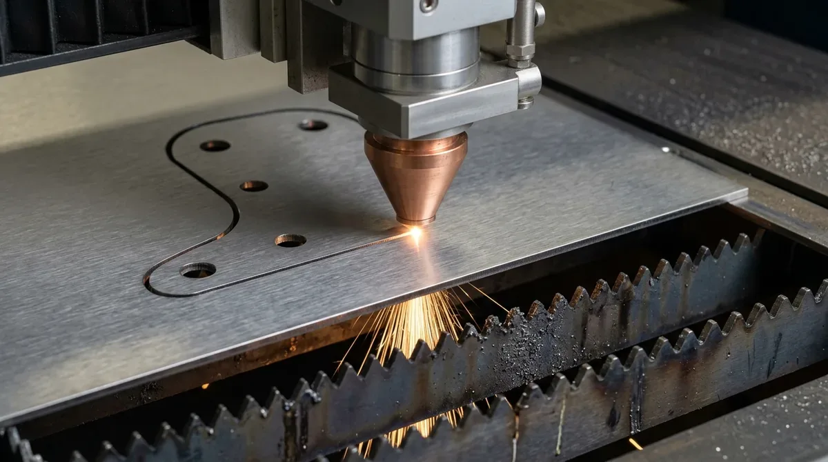
Furthermore, high-pressure assist gases blow molten dross out of the cut kerf immediately. This dynamic process produces narrow kerf slots and clean perpendicular cut edges. Understanding the technical mechanics between solid-state fiber lasers and traditional gas CO2 systems ensures optimal process selection. In this engineering guide, we examine laser beam physics, assist gas dynamics, and critical DFM rules.
Executive Summary & Engineering Takeaways (BLUF)
- Core Focus & DFM Scope: Actionable shop-floor engineering guidelines for CNC Laser Cutting, covering material selection, geometric tolerancing, and defect prevention.
- Cutting & Forming Precision: Fiber laser and abrasive waterjet profiles hold ±0.05 to ±0.10 mm (±0.002″ to ±0.004″); CNC press brake flanges hold ±0.15 mm (±0.006″) and ±0.5° angular accuracy per DIN 6935.
- Edge Quality & Material Gauge: Burr-free nitrogen-assisted laser edges and zero-HAZ cold waterjet kerfs across 0.5 mm (24 Ga) to 50 mm (2.0″) gauges in aluminum, stainless steel, carbon steel, and copper.
- K-Factor & Flat-Pattern DFM: Empirical bend deduction calibration (K = 0.33–0.44) with grain-direction stress relief to prevent flange cracking and springback drift.
- Ex-Factory Turnaround: 4 to 8 business days for laser/waterjet cut and bent sheet metal prototypes; 7 to 12 business days with powder coating, anodizing, or PEM hardware insertion (excluding 3–5 days air transit).
Article Engineering Navigation
- 1. Laser Beam Kinematics: Solid-State Fiber vs Gas CO2 Lasers
- 2. Assist Gas Selection: High-Pressure Nitrogen vs Exothermic Oxygen
- 3. Design for Manufacturing (DFM) Guidelines for Laser Cutting
- 4. Precision Tolerances, Kerf Compensation, and Secondary Bending
- 5. Why Do CNC Laser Cutting Parts Develop Edge Taper, Thermal Distortion, or Bend Cracking?
- 6. Technical Engineering FAQ
1. Laser Beam Kinematics: Solid-State Fiber vs Gas CO2 Lasers
Modern industrial cutting centers predominantly utilize solid-state ytterbium fiber laser resonators. Fiber lasers generate light at an optical wavelength of 1.06 microns. Because this wavelength is ten times shorter than CO2 lasers, metals absorb the beam energy with exceptional efficiency. Consequently, fiber lasers cut thin-to-medium sheet metals up to three times faster than equivalent CO2 systems.
In addition, fiber laser beams transmit directly through flexible optical quartz fibers. This solid-state architecture eliminates complex reflective turning mirrors and beam purge systems required by CO2 machines. However, high-power CO2 lasers still retain minor advantages when slicing thick polymer acrylics or organic woods. Nevertheless, fiber lasers dominate industrial metal blanking due to their remarkable forty-percent wall-plug electrical efficiency.
2. Assist Gas Selection: High-Pressure Nitrogen vs Exothermic Oxygen
The choice of cutting assist gas directly influences cut edge metallurgical quality and processing speed. When processing stainless steel or aerospace aluminum alloys, engineers mandate high-pressure nitrogen assist gas. Nitrogen acts as an inert shielding agent, preventing ambient oxygen from reacting with molten metal. As a result, nitrogen-cut edges emerge completely oxide-free, silvery-bright, and immediately ready for robotic welding or painting.
Conversely, cutting thick carbon structural steel frequently employs industrial oxygen assist gas. Oxygen reacts exothermically with molten iron, generating significant supplemental heat during cutting. Consequently, lower laser wattage penetrates heavy plate thicknesses effectively. Through our precision sheet metal fabrication services, AS Prototypes optimizes gas pressures between twelve and twenty-five bar.
The comparative performance attributes of primary laser technologies are contrasted in the table below.
| System Attribute | Solid-State Fiber Laser | Gas CO2 Laser |
|---|---|---|
| Operating Laser Wavelength | 1.064 μm (near infrared) | 10.6 μm (far infrared) |
| Wall-Plug Electrical Efficiency | 35% to 45% (exceptionally high) | 8% to 12% (moderate) |
| Beam Delivery Mechanism | Flexible quartz optical fiber | External reflective mirror path |
| Thin Metal Cutting Speed (<4 mm) | Extremely high (up to 50 m/min) | Moderate (up to 15 m/min) |
| Reflective Metal Capability (Cu/Al) | Outstanding (high absorption) | Poor (risk of optical resonator damage) |
3. Design for Manufacturing (DFM) Guidelines for Laser Cutting
Executing successful sheet metal blanks requires observing fundamental DFM geometric rules. Minimum hole diameters must equal or exceed the material plate thickness. If a laser pierces a hole smaller than plate thickness, excessive thermal accumulation creates irregular, tapered bores. Therefore, for micro-apertures below material thickness, AS Prototypes incorporates secondary precision CNC milling operations.
Furthermore, engineers maintain minimum web spacing between adjacent cutouts equal to material gauge thickness. Placing cutouts too close together causes localized overheating, resulting in burned web bridges and localized sheet warping. In addition, corner radii should incorporate small fillets rather than zero-radius sharp vertices. Generous blending radii reduce dynamic acceleration deceleration stresses on the CNC gantry motion system.
4. Precision Tolerances, Kerf Compensation, and Secondary Bending
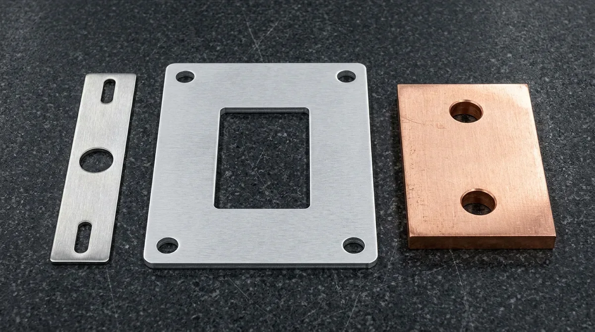
Precision CNC laser cutters deliver outstanding repeatability across complex sheet metal nested profiles. Standard cutting systems maintain linear dimensional tolerances within ±0.05 mm on sheets under three millimeters. CAM software applies dynamic kerf offset compensation automatically. This software calibration ensures finished parts match digital CAD coordinates perfectly regardless of beam focus width.
Moreover, laser-cut flat blanks transition seamlessly to precision CNC press brake bending cells. Laser etching can mark bend alignment lines and part identification numbers during the profiling cycle. Consequently, press brake operators align tooling dies rapidly without manual layout measurement. AS Prototypes operates high-speed multi-kilowatt fiber lasers integrated with automated sheet loader towers to minimize lead times.
The operational guidelines across assist gases and material grades are summarized in the table below.
| Assist Gas Type | Operating Pressure Range | Edge Chemistry & Appearance | Ideal Material Applications |
|---|---|---|---|
| High-Purity Nitrogen (N2) | 15 to 25 bar | 100% oxide-free, mirror-bright | Stainless steel, aluminum alloys, brass, nickel |
| Industrial Oxygen (O2) | 0.5 to 5 bar | Exothermic oxidized scale edge | Thick carbon steel, heavy structural plate |
| Clean Dry Compressed Air | 12 to 18 bar | Slight oxidation, cost-effective | Mild steel brackets, internal non-cosmetic sheet |
| High-Pressure Argon (Ar) | 15 to 20 bar | Completely inert, zero nitriding | Aerospace titanium alloys, medical implants |
5. Why Do CNC Laser Cutting Parts Develop Edge Taper, Thermal Distortion, or Bend Cracking?
Achieving repeatable dimensional accuracy in CNC Laser Cutting requires controlling kerf width offset, heat-affected zone (HAZ) recrystallization, and minimum inside bend radii relative to sheet grain direction. While precision CNC profiling holds ±0.05 to ±0.10 mm (±0.002″ to ±0.004″), placing holes closer than 1.5× material thickness to a bend line or cutting narrow bridges under 1.0× thickness triggers distortion.
Shop-Floor Quantitative Derivation: Flat-Pattern Bend Allowance (BA) & Kerf Offset
In our sheet metal and CNC profiling facility, translating a 3D enclosure or bracket into an accurate 2D flat pattern for CNC Laser Cutting requires exact Bend Allowance (BA) and Bend Deduction (BD) math per DIN 6935. For a 90° bend (θ = π/2 rad) in t = 2.0 mm (14 Ga / 0.078″) material with an inside bend radius R = 2.0 mm (0.078″) and an empirical neutral-axis K-factor of K = 0.38:
BA = θ × (R + K × t) = 1.5708 × (2.0 + 0.38 × 2.0) = 4.335 mm (0.1707″)
With outside setback OSSB = tan(45°) × (R + t) = 4.000 mm, the Bend Deduction is BD = 2 × OSSB − BA = 8.000 − 4.335 = 3.665 mm (0.1443″) per 90° bend. Simultaneously, CNC CAM nesting shifts the cutting path outward by exactly half the beam/stream kerf width (typically rkerf = 0.10 mm / 0.004″ for fiber laser or 0.45 mm / 0.018″ for abrasive waterjet) so the finished part boundary lands at nominal CAD dimension.
Step-by-Step Shop-Floor Execution & Quality Protocol
To bridge CAD intent with repeatable shop-floor delivery, our engineering team enforces a four-stage execution workflow across every prototype and low-volume production batch:
- Step 1: Flat-Pattern Unfolding & Grain-Direction Nesting: Unfold 3D CAD models using material-calibrated K-factors (0.33–0.44) and orient high-stress press-brake bend axes perpendicular to the rolling grain direction of the sheet coil.
- Step 2: Pierce Lead-In & Kerf Offset Programming: Place piercing lead-ins inside scrap cutouts rather than on finished part contours, applying high-pressure nitrogen assist gas or dynamic tilt-head taper compensation.
- Step 3: Vibratory Deburring & Edge Conditioning: Pass profiled blanks through wide-belt orbital deburring and brush-grinding stages to remove micro-dross and establish safe R 0.15 mm (0.006″) broken edges prior to forming.
- Step 4: Optical Angle Controlled Bending & Hardware Insertion: Form flanges on multi-axis CNC press brakes with real-time laser springback compensation (±0.5°), install PEM self-clinching fasteners, and verify geometry on our inspection table.
Shop-Floor Defect Troubleshooting & Corrective Action Matrix
When evaluating part geometry during pre-production DFM review, our manufacturing engineers screen for the following failure modes and apply proven corrective controls:
| Defect / Symptom | Physical Root Cause | Shop-Floor Corrective Action | Recommended DFM Spec Limit |
|---|---|---|---|
| Outer Bend Radius Cracking | Inside bend radius too sharp (R < 0.8t), specifying hard 6061-T6 sheet instead of formable 5052-H32, or bending parallel to grain direction | Specify ductile 5052-H32 aluminum for bent chassis, increase inside punch radius to R ≥ 1.0t–1.5t, and nest flat blanks 90° across the rolling grain. | Min bend radius R ≥ 1.0t (5052-H32) |
| Hole Ovality Near Bend Lines | Cutouts positioned within the plastic deformation zone (< 2t + R from inside bend tangent) | Relocate holes to a minimum distance D ≥ 2.0t + R from the bend line, or add a 1.0t wide bend-relief slot. | Hole-to-bend D ≥ 2t + R |
| Bottom Edge Dross / Slag Burrs | Suboptimal assist gas pressure, nozzle standoff drift, or focal point misalignment | Switch from oxygen to 18–22 bar high-purity nitrogen assist gas and recalibrate capacitive height sensing. | Burr height ≤ 0.03 mm |
| V-Shaped Kerf Edge Taper | Jet stream divergence or beam defocusing through thick plate sections (> 15 mm / 0.60″) | Engage 5-axis dynamic taper-tilt compensation head (±0.05 mm perpendicularity) or post-ream precision H7 bores on a CNC VMC. | Squareness ≤ 0.05 mm |
Engineering Trade-Offs: When NOT to Over-Specify
When to Avoid This Process (Engineering Limitations): Sheet metal profiling and bending cannot natively produce variable-thickness 3D pockets, O-ring seal grooves, or high-stiffness integral bosses without secondary welding or stacked laminations. When an enclosure requires EMI shielding gasket channels, blind threaded bosses, or flatness better than 0.05 mm (0.002″) across mounting pads, hogging the housing from solid 6061-T6 billet on a 3-axis or 4-axis CNC milling center provides superior structural rigidity and hermeticity.
🔗 Related Sheet Metal & Secondary CNC Fabrication Guides:
When specifying CNC Laser Cutting for structural chassis and enclosures, controlling bend springback, edge burr condition, and protective coatings prevents assembly interference. Consult our Precision Sheet Metal Forming: 7 Engineering Best Practices, review Progressive Stamping Die & Forming DFM Rules, and compare corrosion protection in our Complete Metal Surface Finishing Guide.
6. Technical Engineering FAQ
Fiber lasers operate at a 1.06-micron wavelength, which is absorbed far more efficiently by metals. Consequently, they cut thin sheet metal up to three times faster while consuming less electrical power. At AS Prototypes, our engineering team validates these parameters against ISO 2768-mK general tolerances (with critical mating features held to ±0.010 mm / ±0.0004″) and provides 24-hour DFM feedback.
High-pressure nitrogen purges molten metal out of the cut kerf without chemical oxidation. This leaves bright, oxide-free edges that can be powder coated or welded without secondary edge grinding. At AS Prototypes, our engineering team validates these parameters against ISO 2768-mK general tolerances (with critical mating features held to ±0.010 mm / ±0.0004″) and provides 24-hour DFM feedback.
The standard DFM guideline mandates that hole diameters should equal or exceed raw plate thickness. Piercing holes smaller than sheet thickness can cause heat buildup and hole tapering. At AS Prototypes, our engineering team validates these parameters against ISO 2768-mK general tolerances (with critical mating features held to ±0.010 mm / ±0.0004″) and provides 24-hour DFM feedback.
Engineer Precision Custom Sheet Metal Enclosures & Brackets
Eliminate bend springback, hole distortion, and assembly interference before cutting metal. Upload your 3D CAD files (STEP/IGES) and 2D flat-pattern drawings for a dedicated sheet metal DFM review and custom production quotation.
Upload CAD Files for Sheet Metal DFM & Quote