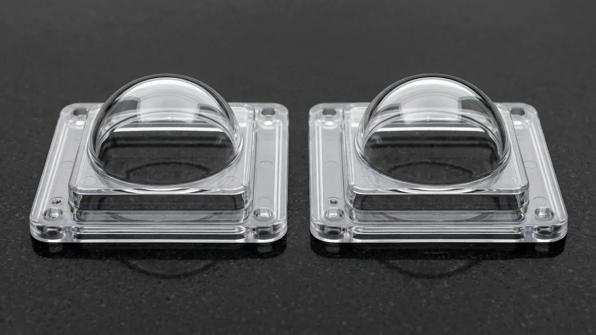
Polycarbonate (PC) ranks among the most versatile amorphous thermoplastics in modern industrial manufacturing. Consequently, polycarbonate injection molding produces exceptionally rugged components requiring glass-like optical clarity and outstanding impact strength. From automotive headlamps to impact-resistant safety shields, polycarbonate withstands harsh mechanical environments reliably.
However, high melt viscosity and extreme hygroscopic sensitivity make polycarbonate challenging to process without defect. In this engineering guide, our injection molding specialists evaluate optimal drying procedures and thermal parameters. Additionally, we examine mold tooling construction, residual stress management, and precision DFM rules.
Executive Summary & Engineering Takeaways (BLUF)
- Mandatory <0.02% Desiccant Drying: Polycarbonate (PC) ester-carbonate linkages undergo rapid hydrolytic chain scission above 250°C if moisture exceeds 0.02% (200 ppm); virgin resin must be dried in a closed-loop dehumidifying desiccant hopper at 120°C (248°F) for 3 to 4 hours (−40°C / −40°F dew point) prior to plastication.
- High-Viscosity Thermal Processing Window: Because amorphous PC exhibits high melt viscosity (processing at 280°C–320°C / 536°F–608°F), molds must be heated via pressurized water or oil thermolators to 80°C–110°C (176°F–230°F) to prevent premature skin freeze-off, flow hesitation, and high molded-in shear stress.
- SPI-A1/A2 Steel & Generous Draft Rules: With low, isotropic mold shrinkage (0.5%–0.7%) and high stiffness (2.3–2.4 GPa), PC grips mold cores tightly; cavities require corrosion-resistant S136/420 ESR stainless steel (48–52 HRC) polished to SPI-A1/A2 diamond mirror finish (Ra 0.01–0.05 μm) and 1.5°–2.0° draft angles.
- Birefringence & Chemical Stress Cracking (ESC): Frozen shear stresses around pinpoint gates induce optical retardation (birefringence) in lenses and catastrophic environmental stress cracking upon contact with alcohols, ketones, or thread-locking adhesives—mitigated via fan/tab gates and 120°C–125°C thermal annealing.
Article Engineering Navigation
- 1. Material Physics and Critical Pre-Drying Protocol
- 2. Polycarbonate Processing Parameter Window
- 3. Managing Residual Stress and Birefringence
- 4. Tooling DFM Guidelines for Polycarbonate
- 5. Quantitative Hydrolytic Degradation, Melt Viscosity & Optical Birefringence Physics
- 6. How Do You Prevent Silver Splay, Optical Flow Lines, and Stress Cracking in Molded PC?
- 7. When NOT to Choose Unfilled Polycarbonate & PC Molding DFM Checklist
- 8. Technical Engineering FAQ
1. Material Physics and Critical Pre-Drying Protocol
Core Physical Principles and Shop-Floor Execution
Polycarbonate polymers absorb atmospheric moisture rapidly due to polarized carbonate ester groups along their molecular chains. If processors mold moist pellets, boiling water vapor triggers aggressive hydrolytic degradation inside the heated screw barrel. Consequently, parts suffer from severe embrittlement, structural weakness, and cosmetic silver splay streaks.
Therefore, injection molding engineers must utilize dehumidifying desiccant hopper dryers prior to production. Raw resin pellets require continuous pre-drying at 120 degrees Celsius for three to four hours. Furthermore, processing facilities must maintain moisture levels strictly below 0.02 percent to ensure full mechanical impact retention.
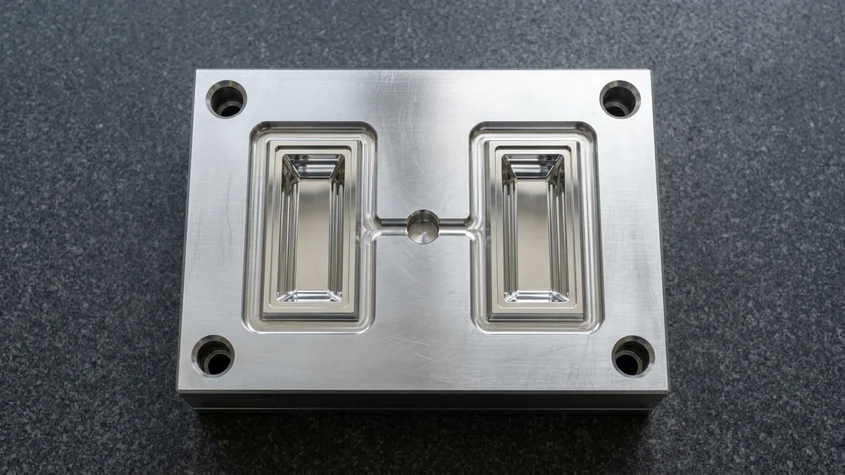
To prevent flow hesitation and optical weld lines when molding viscous polycarbonate, Figure 1 shows a precision-machined S136 stainless tool steel optical injection mold cavity block on granite featuring two diamond-polished rectangular stepped light-guide cavities fed by a central sprue and wide fan gates.
2. Polycarbonate Processing Parameter Window
Primary Process Capabilities and Equipment Architecture
Due to its high molecular weight and rigid backbone, molten polycarbonate exhibits elevated shear viscosity. As a result, molding machines require high melt temperatures and substantial injection pressures to fill complex cavities. The engineering process window below outlines optimal molding parameters across common polycarbonate formulations.
| Processing Parameter | Standard Unfilled PC | Glass-Filled PC (GF20) | Optical Grade PC |
|---|---|---|---|
| Drying Temp & Time | 120°C for 3 to 4 hours | 120°C for 3 to 4 hours | 120°C for 4 hours (Dew point -40°C) |
| Melt Temperature | 280°C to 310°C | 290°C to 325°C | 270°C to 295°C |
| Mold Temperature | 80°C to 110°C | 90°C to 120°C | 90°C to 115°C |
| Injection Pressure | 90 to 140 MPa | 100 to 160 MPa | 80 to 120 MPa |
| Linear Mold Shrinkage | 0.5% to 0.7% | 0.2% to 0.4% | 0.5% to 0.6% |
| Recommended Gates | Edge gate, fan gate, sprue gate | Direct sprue, sub gate | Fan gate, contour edge gate |
Elevated mold temperatures between 80 degrees and 110 degrees Celsius remain vital throughout production. Specifically, hot mold steel promotes smooth molten resin flow and prevents premature skin layer freezing. In addition, explore our turnkey custom plastic injection molding services for high-yield production runs.
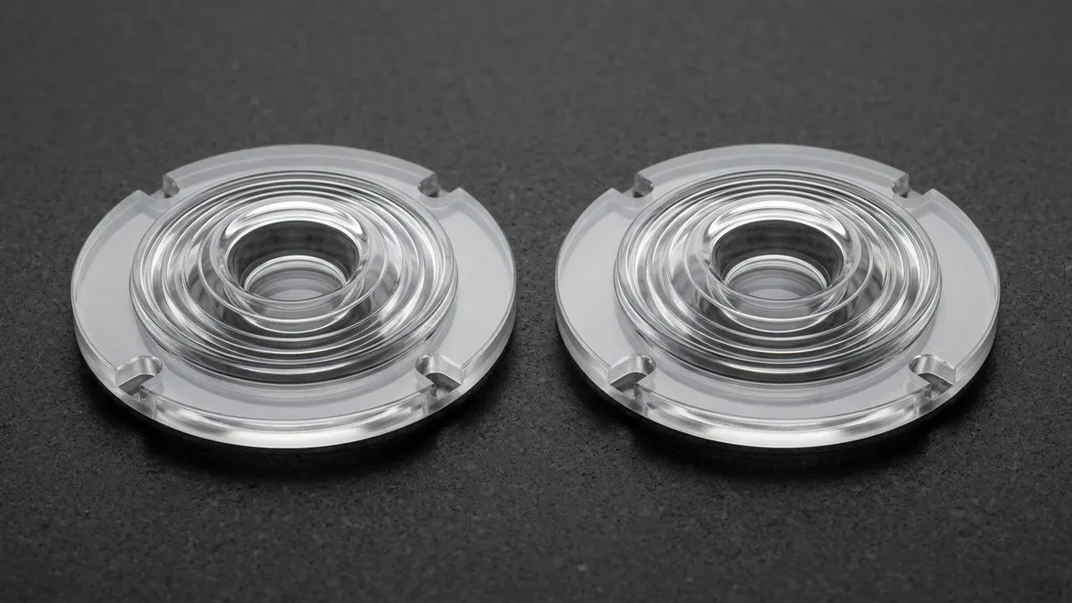
As shown in Figure 2, two optically clear injection-molded polycarbonate circular total-internal-reflection (TIR) collimator lenses rest flat on black granite, exhibiting glass-like internal clarity, concentric stepped optical rings, and birefringence-free mounting flanges achieved through high-temperature mold conditioning.
3. Managing Residual Stress and Birefringence
Critical Process Parameters and Tooling Selection
Because polycarbonate freezes rapidly under shear pressure, molded components frequently retain internal frozen residual stresses. In transparent optical lenses, differential stress states cause optical birefringence and chromatic aberration. Furthermore, molded parts with high residual stress crack prematurely upon exposure to cleaning solvents.
To evaluate stress distribution, quality engineers inspect transparent components using cross-polarized photoelastic polariscopes. If high stress concentrations appear around gate junctions, engineers execute thermal stress-relief annealing. Consequently, baking parts at 125 degrees Celsius for two hours relaxes frozen polymer chains safely. Discover our precision components for automotive lighting and optical enclosures.
4. Tooling DFM Guidelines for Polycarbonate
Practical Design-for-Manufacturing (DFM) Guidelines
Designing steel mold cavities for polycarbonate demands strict adherence to draft angles and venting channels. First, provide generous draft angles of at least 1.5 to 2.0 degrees on all vertical shutoffs. Because polycarbonate contracts minimally during solidification, generous draft prevents heavy surface scuffing during ejection.
Second, implement large runner diameters and avoid restrictive pinpoint gates. Pinpoint gates generate excessive shear heating, causing material discoloration and jetting turbulence. Finally, incorporate generous parting line vents measuring 0.02 mm to 0.03 mm deep to exhaust compressed cavity air cleanly.
5. Quantitative Hydrolytic Degradation, Melt Viscosity & Optical Birefringence Physics
Hydrolytic Chain Scission Kinetics and Pre-Drying Dew-Point Thresholds
Polycarbonate (PC) is an amorphous engineering thermoplastic connected by carbonate ester linkages (–O–CO–O–) that undergo rapid hydrolytic chain scission if moisture is present above 0.02% (200 ppm) at injection melt temperatures of 280°C–320°C (536°F–608°F). Even trace residual water reacts chemically with the molten polymer backbone, slashing molecular weight (Mw) by 20%–35% in a single barrel residence cycle and destroying Notched Izod impact strength.
• Hydrolytic Moisture Ceiling: MH2O ≤ 0.015%–0.020% (Desiccant hopper drying at 120°C / 248°F for 3.5–4.0 hours at −40°C dew point)
• Optical Stress Birefringence Retardation: Γ = CB × Δσ × d [nm] (where CB ≈ 78 × 10⁻¹² Pa⁻¹ Brewster photoelastic constant for PC)
• Environmental Stress Cracking Threshold: σresidual + σapplied < σESC,crit (Thermal stress-relief anneal at 120°C–125°C for 1–2 hours)
High Melt Viscosity vs. Mold Steel Temperature (85°C–120°C / 185°F–248°F)
Unlike high-flow ABS or Polypropylene whose viscosity drops sharply under high shear rates, Polycarbonate exhibits a relatively flat Newtonian viscosity plateau until extreme shear rates are reached. Trying to force PC into a cold mold (< 60°C) freezes a thick, highly stressed skin layer instantly; running pressurized hot-oil or high-temp water thermolators at 85°C–120°C (185°F–248°F) allows polymer chains to relax before vitrification, cutting molded-in stress in half.
Optical Transmission (88%–90%), Haze (< 1%), and Birefringence Control
When molding optical lenses, LiDAR sensor covers, and medical fluid sight glasses, frozen shear stress creates optical birefringence—splitting polarized light into rainbow interference fringes and distorting laser wavefronts. Minimizing birefringence requires oversized fan or tab gates (gate thickness = 70%–85% of wall thickness), slow-to-moderate laminar fill speeds (25–50 mm/s), and SPI A-1 (#3 diamond buff, Ra ≤ 0.012 μm) hardened H13 or S136 stainless mold cores.
6. How Do You Prevent Silver Splay, Optical Flow Lines, and Stress Cracking in Molded PC?
Eliminating Gate Jetting, Black Specks, and Ejector Pin Crazing
Because molten Polycarbonate is stiff and viscous, shooting melt through a tiny pinpoint gate into an open optical cavity causes “worm-like” jetting snakes that cool immediately and leave permanent optical flow welds. Furthermore, because PC shrinks tightly onto internal mold cores (0.5%–0.7% linear shrinkage) with high glass-transition stiffness (Tg ≈ 147°C), insufficient draft angles (< 1.0°) cause severe ejector-pin micro-crazing during part ejection.
| Observed Defect / Symptom | Physical Root Cause | Quantitative Process Threshold | Corrective Shop-Floor Action | Inspection Verification Method |
|---|---|---|---|---|
| Silver splay streaks and brittle impact fracture | Hydrolytic steam bubbles from inadequately dried PC resin granules | Pellet moisture content > 0.020% (200 ppm) or hopper dew point > −25°C | Dry in closed-loop desiccant dryer at 120°C for 4 hours (dew point −40°C) and verify via Karl Fischer moisture analyzer | Karl Fischer titration (≤ 150 ppm H2O) and ASTM D256 Notched Izod drop check |
| Micro-cracking and crazing around metal inserts or screws | High frozen tensile hoop stress combined with chemical/oil exposure | Molded-in residual stress > 12 MPa around cold brass knurled insert | Pre-heat metal inserts to 110°C before overmolding, maintain boss outer diameter (OD) ≥ 2.0×–2.2× insert OD, or use post-molded ultrasonic inserts | Ethyl acetate / isopropanol solvent stress test (ISO 22088-3) and polariscope inspection |
| Optical jetting snakes and high haze (> 2%) on clear lenses | High shear velocity through undersized gate into cold mold cavity | Gate depth < 50% of wall thickness or mold temperature < 80°C (176°F) | Widen to fan/edge gate (75% wall depth), run slow-fast-slow multi-stage injection profile, and raise mold temp to 100°C–115°C | ASTM D1003 hazemeter (< 0.8% haze, > 89% luminous transmittance) and cross-polarizer check |
| Black carbonized specks embedded in transparent PC parts | Polymer hang-up degradation inside barrel dead spots or over-temperature | Barrel residence time > 6 minutes or melt temperature > 330°C (626°F) | Purge barrel with PMMA/acrylic purge compound before shutdown, use low-compression PC screw (L/D 20:1), and cap melt at 310°C | Cleanroom D65 illuminated visual inspection per TAPPI T437 speck chart |
Cross-Polarizer Photoelastic Inspection and ISO 22088-3 Solvent Stress Testing
Before releasing transparent or structural PC housings to production, quality engineers inspect sample parts between crossed circular polarizers to map fringe density around gates and bosses, and perform 60-second ethyl acetate/isopropanol solvent swab tests (ISO 22088-3) to verify that residual tensile stress sits safely below the environmental stress cracking (ESC) threshold.
7. When NOT to Choose Unfilled Polycarbonate & PC Molding DFM Checklist
When NOT to Specify Virgin Unfilled Polycarbonate
Hardware designers should avoid specifying standard unfilled Polycarbonate in three demanding service environments:
- Frequent Chemical Wipe-Down with Ketones, Esters, or Harsh Hospital Disinfectants: Unfilled PC is vulnerable to environmental stress cracking under quaternary ammonium, acetone, or aggressive solvent exposure; switch to a PC/PBT alloy (Xenoy), PC/polyester blend, or Polysulfone (PSU/PPSU).
- Thin-Wall Complex Enclosures With Long Flow Ratios (L/t > 150:1): Standard optical/structural PC has a low melt flow rate (MFR 6–15 g/10 min) that struggles to fill thin 1.2 mm ribs without excessive clamping tonnage; select PC/ABS alloy or high-flow branched PC grades for thin electronics housings.
- Continuous Sliding Wear or Sharp Notched Fatigue Loading: Despite its high unnotched toughness, PC has high notch sensitivity (critical corner radius < 0.25 mm drops impact energy by 80%) and poor unlubricated sliding wear resistance; use POM-C, PA66, or PTFE-lubricated PC for moving gears and latches.
Four-Step Polycarbonate Injection Molding DFM Verification Protocol
- Enforce Generous Internal Fillet Radii (R ≥ 0.5–0.8 mm / 0.020–0.031 in): Eliminate all sharp internal corners on ribs, bosses, and snap-fits to prevent notch-induced brittle transition failure under impact.
- Specify Generous Draft Angles (1.5°–2.0° Standard, 2.5°+ Textured): Because PC exhibits high glass-transition temperature and low mold shrinkage, provide at least 1.5° draft on polished cores to prevent ejection drag marks and stress whitening.
- Keep Nominal Wall Thickness Between 1.8 mm and 3.2 mm (0.070–0.125 in): Avoid thin sections under 1.5 mm that require high injection shear stress, and core out sections thicker than 3.5 mm to prevent internal vacuum voids.
- Design Boss Outer Diameter (OD) ≥ 2.0×–2.5× Screw Diameter and Avoid Thread-Cutting Screws: Keep nominal boss wall ≤ 0.60× adjacent wall thickness, use thread-forming plastite screws or heat/ultrasonic brass inserts with smooth lead-in chamfers, and strictly forbid hydrocarbon thread-locking compounds (Loctite) that chemically crack Polycarbonate bosses.
🔗 Related Optical Tooling, Injection Molding & Enclosure Guides
8. Technical Engineering FAQ
Residual moisture above 0.02% triggers hydrolysis at 280–320°C barrel temperatures, cleaving polymer chains, causing silver splay streaks, and reducing impact strength by 60–80%. Always pre-dry pellets in a desiccant dryer at 120°C for 3–4 hours to confirm moisture below 0.015% before molding.
Polycarbonate has a 145–150°C glass transition temperature and 3×–5× higher melt viscosity than ABS, causing premature skin freezing and >1,500 bar pressure spikes in cold cavities. Maintain mold steel temperatures at 80–110°C to ensure uniform cavity packing, fuse strong weld lines, and minimize residual stress.
Restrictive pinpoint or submarine gates under Ø1.0 mm generate shear rates above 40,000 s⁻¹, causing melt fracture, jetting, and optical gate blush. Specify Ø5.0–8.0 mm full-round runners feeding wide fan or edge gates with 0.5–0.8 mm lands and depths at 60–75% of wall thickness.
Polycarbonate suffers Environmental Stress Cracking (ESC) when tensile hoop stress exceeds 10–15 MPa during exposure to acetone, isopropyl alcohol, or anaerobic threadlockers. Use heat-staked brass inserts in bosses ≥2.2× insert OD instead of cold press-fits, ban cyanoacrylate adhesives, and anneal stressed parts at 120–125°C.
Ready to Validate Your CAD Design for Precision Manufacturing?
Upload your 3D CAD models (STEP, IGES, SolidWorks) and 2D engineering drawings for a comprehensive DFM engineering review and custom quotation from our in-house CNC machining and prototyping team.
Request a Custom DFM Review & Quote →