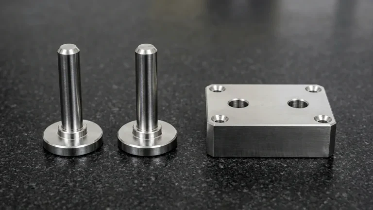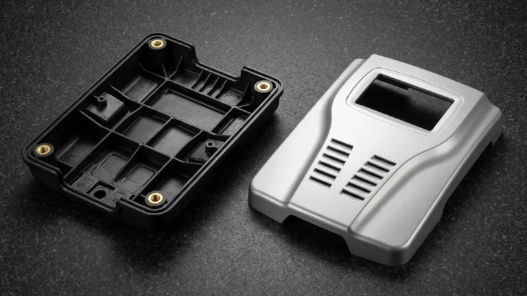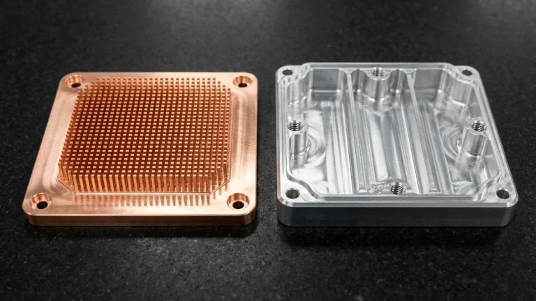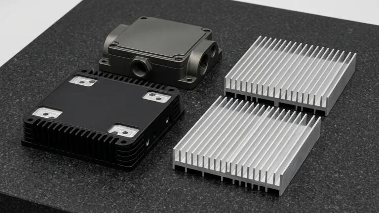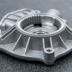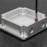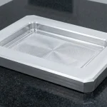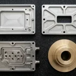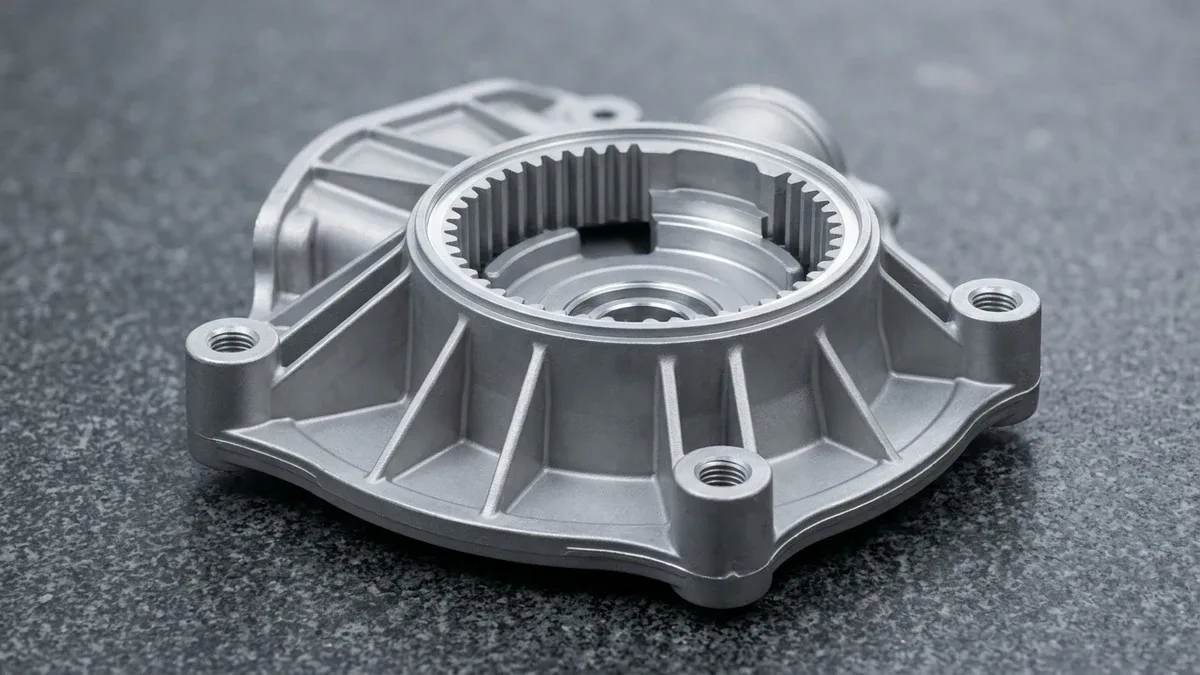
When hardware engineers specify high-volume automotive actuator housings, optical transceiver cages, precision gear hubs, and luxury consumer bezels, this zinc die casting guide establishes the metallurgical and Design for Manufacturing (DFM) rules required for repeatable production. Hot-chamber zinc casting bridges the structural gap between molded polymers and cold-chamber aluminum castings.
Because Zamak alloys melt at 380 to 387 °C (375 to 404 °C for ZA-8) and exhibit high fluidity under hydraulic plunger pressure (15 to 35 MPa), liquid zinc fills 0.60 to 1.00 mm structural walls and 0.50 mm miniature ribs in 10 to 25 ms, forming a 0.30 to 0.50 mm dense chill skin.
At our in-house die casting foundry, mold toolroom, and CNC machining facility at our in-house die-casting and CNC facility, we integrate 88-ton to 280-ton hot-chamber presses with hardened AISI H13 tooling, high-speed 3-axis and 4-axis CNC tapping centers, and automated electroplating lines.
Executive Summary & Engineering Takeaways (BLUF)
- Submerged Gooseneck Mechanics: Hot-chamber presses use a submerged gooseneck in a 415 to 430 °C melt bath at 15 to 35 MPa plunger pressure and 35 to 55 m/s gate velocity, delivering 15 to 25 s cycle times for Zamak 3, Zamak 5, Zamak 2, Zamak 7, and ZA-8.
- Alloy Selection (ASTM B86 / B240 & EN 12844 / 1774): Zamak 3 (AG40A / ZP3, 6.6 g/cm3, 283 MPa ultimate tensile strength [UTS]) maximizes dimensional stability; Zamak 5 (AC41A / ZP5, 328 MPa UTS, 1% Cu) boosts hardness (91 HB); Zamak 2 (AC43A / ZP2, 359 MPa UTS, 100 HB) resists wear; ZA-8 (ZP8, 6.3 g/cm3, 374 MPa UTS) serves heavy bearing loads.
- H13 Tooling Life: Vacuum-hardened AISI H13 / SKD61 / ASSAB 8407 cavities (46 to 50 HRC per ASTM E18) achieve 500,000 to 1,000,000+ shots due to low thermal fatigue stress against 160 to 200 °C die faces.
- Thin-Wall DFM & Tolerances: Design 0.60 to 1.00 mm walls (0.50 mm miniature features) with 0.5° to 1.0° outer and 1.0° to 1.5° inner draft, 0.7% linear shrinkage (Zamak 3/5), NADCA / ISO 8062-3 DCTG 4–5 (±0.05 to ±0.08 mm first 25 mm) as-cast, and ±0.010 to ±0.020 mm via 3/4-axis CNC machining.
- Chill Skin & Blister-Free Plating: Preserve the 0.30 to 0.50 mm dense chill skin (CNC skim cuts ≤ 0.15 to 0.25 mm to avoid > 0.50 mm subsurface pores) and cap Zamak 3 post-plate baking at 70 to 85 °C (< 100 °C creep limit) during Cu-Ni-Cr electroplating or RoHS trivalent passivation (ASTM B117 48 to 240 hours).
Article Engineering Navigation
- 1. How Does Hot-Chamber Zinc Die Casting Work with a Submerged Gooseneck?
- 2. How to Select Zinc Alloys: Zamak 3, Zamak 5, Zamak 2, Zamak 7 vs. ZA-8?
- 3. Why Do AISI H13 / ASSAB 8407 Zinc Molds Exceed 500,000 Shots?
- 4. How to Design Thin-Wall Zinc Castings: Walls, Draft, Ribs & Cored Bosses?
- 5. What Tolerances Do ISO 8062-3 DCTG 4–5 & 3/4-Axis CNC Post-Machining Hold?
- 6. How Do Chill-Skin Preservation & Low-Bake Plating Prevent Blistering?
- 7. Technical Engineering FAQ
1. How Does Hot-Chamber Zinc Die Casting Work with a Submerged Gooseneck?
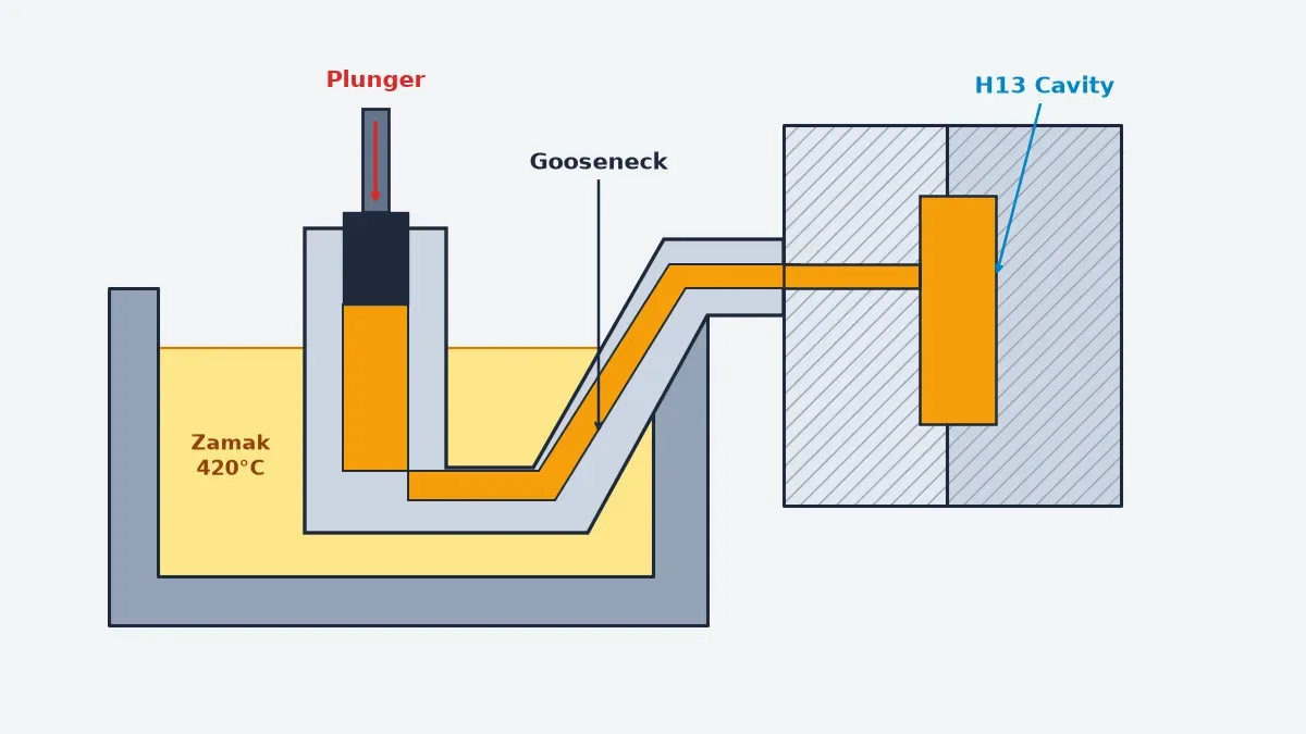
Unlike cold-chamber aluminum die casting that ladles molten metal into an external shot sleeve every cycle, zinc die casting runs on automated hot-chamber presses. In our 88-ton to 280-ton workcells, the nitrided steel gooseneck and hydraulic plunger remain submerged inside the 415 to 430 °C melt pot.
Closed-loop servo-valves execute a three-stage injection profile. During first-stage slow approach (0.15 to 0.35 m/s), the plunger descends past the gooseneck intake ports, sealing the chamber and pushing runner air smoothly toward the vents without turbulent wavefolding or premature freeze-off at the heated nozzle tip.
As illustrated in the hot-chamber gooseneck schematic below, second-stage acceleration drives the plunger at 1.5 to 3.2 m/s, propelling liquid Zamak through the tangential fan gate at 35 to 55 m/s (115 to 180 ft/s). The cavity fills in 10 to 25 ms under 15 to 35 MPa (2,175 to 5,076 PSI) third-stage intensification pressure.
Because the submerged gooseneck eliminates manual ladling and minimizes heat loss between the furnace pot and die sprue, hot-chamber presses achieve 15 to 25 s cycle times. This rapid solidification against water-cooled H13 steel forms a fine-grained 0.30 to 0.50 mm outer chill skin with superior fatigue strength.
Shop-Floor Calculation: Clamping Tonnage, Gate Area & Cavity Shrinkage
Tooling engineers calculate press clamping force (Fclamp), tangential gate area (Agate), and expanded cavity length (Lcavity) from projected area (Aproj), cavity pressure (Pspec), shot mass (Mshot), density (ρZn = 6.6 g/cm3), fill time (tfill), gate velocity (vgate = 35–55 m/s), and linear shrinkage (Slinear = 0.7% for Zamak 3/5):
Fclamp = ksafety × Pspec × Aproj | Agate = Mshot ÷ (ρZn × tfill × vgate) | Lcavity = Lnom × (1 + Slinear)
Worked Example Part A (Clamping Force): A 2-cavity Zamak 3 housing plus runner has total Aproj = 156.6 cm2 (24.27 in2). At Pspec = 28 MPa (4,061 PSI / 285.5 kgf/cm2) and ksafety = 1.25, required clamping force is Fclamp = 548.10 kN = 55.9 metric tons-force (tf) (61.6 US short tons), selecting an 88-ton (863 kN) press.
Worked Example Part B (Gate Area & Shrinkage): Filling a 92 g (3.25 oz) cavity in 0.016 s at vgate = 38 m/s (1,496 in/s) requires Agate = 22.93 mm2 (0.0355 in2; 0.55 × 41.7 mm fan gate). An Lnom = 80.00 mm (3.1496 in) housing at Slinear = 0.70% requires Lcavity = 80.560 mm (3.1717 in).
2. How to Select Zinc Alloys: Zamak 3, Zamak 5, Zamak 2, Zamak 7 vs. ZA-8?
Our foundry melts 99.99% Special High Grade (SHG) virgin zinc ingots per ASTM B86 / B240 and EN 12844 / 1774, verified per lot via spark optical emission spectroscopy (OES). Keeping trace lead (< 0.003%), cadmium (< 0.002%), and tin (< 0.001%) below threshold limits prevents intergranular corrosion and humid blistering.
In the Zamak family (Zink-Aluminium-Magnesium-Kupfer), 3.8% to 4.3% aluminum forms a near-eutectic liquid that maximizes fluidity and inhibits iron dissolution on the submerged gooseneck. Adding 0.02% to 0.06% magnesium passivates grain boundaries, while copper additions (1.0% to 3.0% Cu) precipitate epsilon-phase hardeners.
Zamak 3 (ASTM AG40A / EN ZP3 / JIS ZDC2, 4.0% Al, 0.04% Mg, 6.6 g/cm3, 381–387 °C melt) accounts for over 70% of precision zinc die castings. Used below 70 to 85 °C (< 100 °C creep threshold), it delivers 283 MPa UTS, 221 MPa yield, 7%–10% elongation, and 82 HB hardness.
Zamak 5 (ASTM AC41A / EN ZP5 / JIS ZDC1, 380–386 °C melt) adds 1.0% Cu to reach 328 MPa UTS, 250 MPa yield, and 91 HB hardness for automotive actuator gears operating up to 85 °C. Zamak 2 (ASTM AC43A / EN ZP2, 3.0% Cu, 6.8 g/cm3) reaches 359 MPa UTS and 100 HB for self-lubricating wear bushings.
Zamak 7 (ASTM AG40B) lowers magnesium to 0.01% with trace nickel, boosting elongation to 10% to 13% for cold staking and 0.50 mm optical transceiver walls. ZA-8 (EN ZP8 / ZL0810, 8.4% Al, 1.0% Cu, 6.3 g/cm3, 375–404 °C melt) is the highest-strength zinc alloy (374 MPa UTS, 103 HB) compatible with hot-chamber presses.
By contrast, higher-aluminum alloys like ZA-12 (11% Al, 377–432 °C melt) and ZA-27 (27% Al, 425 MPa UTS, 376–484 °C melt) require bath temperatures above 450 °C, accelerating iron pickup (Fe > 0.10%) and FeAl3 sludge formation that erode submerged goosenecks and mandate cold-chamber presses.
| Alloy Grade | Composition | Melting / Density | UTS / Yield | Elong. / Hardness | Shrinkage & Chamber |
|---|---|---|---|---|---|
| Zamak 3 (AG40A / ZP3 / ZDC2) | 4.0% Al, 0.04% Mg | 381–387 °C | 6.6 g/cm3 | 283 / 221 MPa (41 / 32 ksi) | 7–10% | 82 HB | 0.6%–0.7% | Hot-chamber (0.60 mm wall) |
| Zamak 5 (AC41A / ZP5 / ZDC1) | 4.0% Al, 1.0% Cu, 0.04% Mg | 380–386 °C | 6.6 g/cm3 | 328 / 250 MPa (48 / 36 ksi) | 5–7% | 91 HB | 0.6%–0.7% | Hot-chamber (0.70 mm gears) |
| Zamak 2 (AC43A / ZP2) | 4.0% Al, 3.0% Cu, 0.035% Mg | 379–390 °C | 6.8 g/cm3 | 359 / 280 MPa (52 / 41 ksi) | 3–7% | 100 HB | 0.6%–0.7% | Hot-chamber (wear locks) |
| Zamak 7 (AG40B) | 4.0% Al, 0.01% Mg, 0.01% Ni | 381–387 °C | 6.6 g/cm3 | 283 / 215 MPa (41 / 31 ksi) | 10–13% | 80 HB | 0.6%–0.7% | Hot-chamber (0.50 mm cages) |
| ZA-8 (ZP8 / ZL0810) | 8.4% Al, 1.0% Cu, 0.02% Mg | 375–404 °C | 6.3 g/cm3 | 374 / 290 MPa (54 / 42 ksi) | 6–10% | 103 HB | 0.7%–0.8% | Hot-chamber (0.80 mm mounts) |
| ADC12 Al (Cold-Chamber Ref) | 10.8% Si, 2.5% Cu | 515–580 °C | 2.7 g/cm3 | 310 / 165 MPa (45 / 24 ksi) | 1.5–3% | 85 HB | 0.5%–0.6% | Cold-chamber (1.50 mm+ walls) |
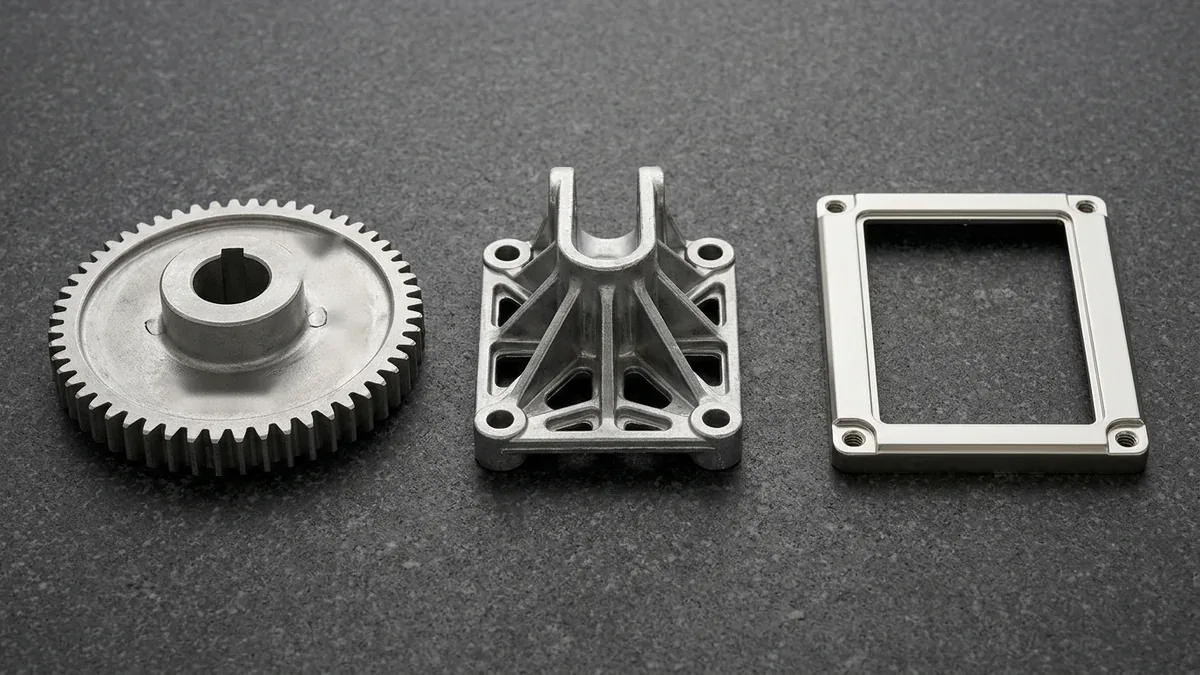
As shown in the production Zamak components below, matching the alloy to the mechanical load allows net-shape casting of involute spur gears with broached keyways (Zamak 5), thin-ribbed structural clevis brackets (Zamak 3), and decorative satin chrome-plated bezels with roll-form tapped bosses.
3. Why Do AISI H13 / ASSAB 8407 Zinc Molds Exceed 500,000 Shots?
Because molten zinc enters the cavity at 415 to 430 °C rather than 660 to 685 °C for aluminum, thermal shock against the water-cooled die face (160 to 200 °C) drops by over 240 °C. While aluminum dies suffer heat checking after 80,000 to 120,000 shots, zinc production molds routinely achieve 500,000 to 1,000,000+ shots.
As illustrated in the two-cavity mold block below, our in-house toolroom machines multi-cavity inserts from Electro-Slag Remelted (ESR) AISI H13 (1.2344 / SKD61) or DIEVAR steel vacuum-hardened to 46 to 50 HRC (ASTM E18). Symmetric runners feed triangular fan gates, while four overflow wells and corrugated chill vents evacuate air.
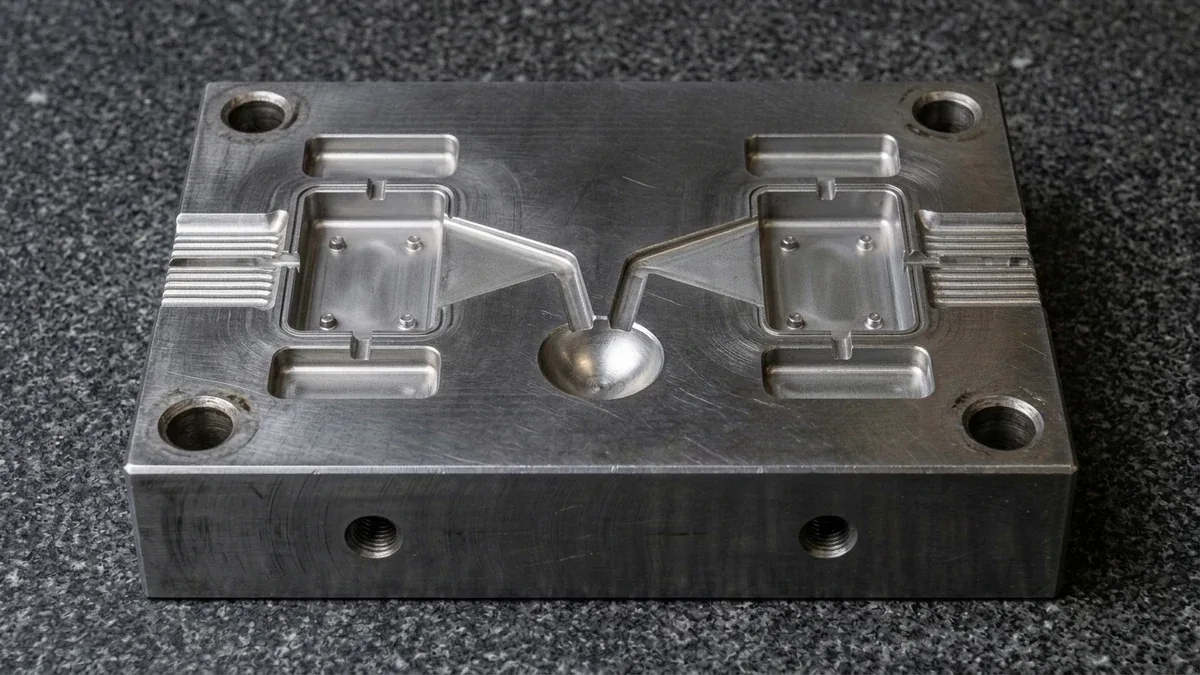
To prevent molten zinc from soldering onto small core pins during high-velocity impingement, our toolmakers apply gas oxynitriding or Physical Vapor Deposition (PVD) CrN coatings (650 to 750 HV microhardness per ASTM E384). Every production mold follows a four-stage toolroom engineering protocol:
- Simulate Gate Velocity & Overflow Placement: Run mold-flow fill simulations to balance symmetric runners, sizing triangular fan gates at 0.35 to 0.80 mm depth and positioning peripheral overflow wells (15% to 25% of part volume) opposite the gate to capture cold front metal.
- Rough Machine, Vacuum Harden & Temper H13 Inserts: Rough-mill ESR AISI H13 / ASSAB 8407 blocks on 3-axis vertical machining centers (VMCs) with 0.25 mm grinding stock, then vacuum-quench and triple-temper to 46 to 50 HRC per ASTM E18.
- Finish Mill, Wire-EDM Shutoffs & Polish Cavities: High-speed hard-mill cavity contours, cut core pin holes and slide shutoffs within ±0.005 mm via slow-wire Electrical Discharge Machining (EDM), and diamond-polish cosmetic plating faces to SPI A-2 (Ra ≤ 0.05 to 0.10 µm).
- Grind Corrugated Chill Vents & Validate T1 Thermal Balance: Surface-grind 0.08 to 0.12 mm corrugated vents along the parting line to exhaust cavity gas without flashing, then verify internal density on T1 samples using Archimedes density balances and Wire-EDM cross-sectioning.
4. How to Design Thin-Wall Zinc Castings: Walls, Draft, Ribs & Cored Bosses?
To prevent internal shrinkage porosity and reduce part mass (Zamak density 6.6 g/cm3; ZA-8 6.3 g/cm3), design structural housings with uniform 0.60 to 1.00 mm (0.024″ to 0.039″) nominal walls. Reserve 0.50 mm (0.020″) walls for miniature features under 25 mm flow length, and replace thick pads with ribbed webs.
Because solidifying zinc contracts 0.6% to 0.8% linearly (0.006 to 0.008 in/in) onto internal cores while pulling away from outer cavity walls, inner surfaces require roughly double the draft of outer walls. Specify 0.5° to 1.0° outer draft and 1.0° to 1.5° inner core draft to prevent ejection galling and drag marks.
Intersecting ribs must be sized at 0.6× to 0.7× the adjacent nominal wall thickness with R 0.50 to R 1.50 mm root fillets. Oversized rib roots create localized thermal hot spots that contract during solidification, pulling sink depressions onto the opposite Class A cosmetic surface and ruining mirror chrome plating.
Core out all mounting bosses thicker than 3.0 mm using core-saver pins to maintain a uniform 0.80 to 1.20 mm annular wall. Cored pilot holes can reach length-to-diameter (L/D) ratios up to 4:1 for blind holes and 6:1 for through holes when supported by opposing mold halves.
Shop-Floor Calculation: Draft Angle Wall Offset & Roll-Form Tap Pilot Sizing
Design engineers calculate single-side draft wall offset (ΔW) over feature depth (H) at draft angle (θ), and size DIN 2174 chipless roll-form tap pilot bores (Dpilot) from thread major diameter (Dmajor) and pitch (P) at 65%–70% thread engagement:
ΔW = H × tan(θ) | Wbase = Wtop + ΔW | Dpilot(roll) = Dmajor − (0.45 × P)
Worked Example Part A (Draft Offset): On a H = 22.00 mm (0.8661 in) cage wall at θouter = 0.75°, single-side offset is ΔWouter = 22.00 × 0.01309 = 0.288 mm, thickening a 0.80 mm top wall to 1.088 mm at the base. At θinner = 1.25°, inner taper is ΔWinner = 0.480 mm/side (0.960 mm total).
Worked Example Part B (Roll-Form Pilot Hole): For an M3 × 0.5 thread in ductile Zamak 3, a DIN 2174 chipless roll-form tap requires Dpilot = 3.00 − (0.45 × 0.50) = 2.775 mm ≈ ⌀ 2.78 mm (0.1094 in), versus ⌀ 2.50 mm for cutting taps. Cold-forming forms threads without severing the dense chill skin.
5. What Tolerances Do ISO 8062-3 DCTG 4–5 & 3/4-Axis CNC Post-Machining Hold?
Steel-safe features formed entirely within one mold half achieve NADCA Precision and ISO 8062-3 DCTG 4–5 linear tolerances (±0.05 to ±0.08 mm over the first 25 mm). Dimensions crossing the parting line or moving side cores require an additional +0.08 to +0.15 mm allowance to account for dynamic die clamping clearance.
When assemblies require ISO H7 (+0.015/0 mm) bearing bores, O-ring sealing faces, or zero-draft datum surfaces, castings move to our high-speed 3-axis and 4-axis CNC vertical machining centers. Using pneumatic 3-2-1 kinematic fixtures referencing steel-safe datum pads, we hold ±0.010 to ±0.020 mm on critical features and ISO 2768-mK on general dimensions.
To prevent exposing subsurface pores (> 0.50 mm depth), CAM programmers cap face-milling and boring skim cuts at 0.15 to 0.25 mm within the 0.30 to 0.50 mm dense chill skin. Rather than cutting threads with fluted taps that sever grain fibers, we use DIN 2174 chipless roll-form taps for M2.0 to M8.0 (ISO 1502 6H) threads.
Inside our 20 °C ± 1 °C climate-controlled metrology lab, quality engineers verify geometrical tolerances on a Zeiss Bridge Coordinate Measuring Machine (CMM), 2.5D Optical Video Measuring System (VMS), Mitutoyo 3-point internal bore micrometers, Class ZZ GO/NO-GO pin gauges, and ISO 4287 contact stylus profilometers, paired with 3.5 to 6.0 bar air pressure-decay leak testing.
| Feature / Parameter | As-Cast Hot-Chamber | 3/4-Axis CNC Post-Machined | Shop-Floor DFM & Inspection Rule |
|---|---|---|---|
| Linear Tolerance (First 25 mm) | ±0.05 to ±0.08 mm (NADCA / ISO 8062-3 DCTG 4–5) | Critical CNC Features (±0.010–0.020 mm) / General ISO 2768-mK | Add +0.08 to +0.15 mm across parting line; Zeiss CMM verify |
| Wall & Skim Cut Depth | 0.60–1.00 mm (0.50 mm miniature) | 0.15–0.25 mm max skim cut | Preserve the 0.30–0.50 mm skin; avoid > 0.50 mm subsurface pores |
| Draft Angles & Bore Cylindricity (⌭) | 0.5°–1.0° outer | 1.0°–1.5° inner draft | 0.0° walls / ISO H7 (+0.015/0 mm) bore cylindricity within 0.010 mm | Verify H7 bores via Mitutoyo 3-point internal micrometers |
| Flatness (⏥) & Perpendicularity (⊥) | Flatness within 0.08 mm per 25 mm | Flatness within 0.015 mm | Perpendicularity within 0.020 mm | High-speed PCD face milling; Zeiss Bridge CMM probing |
| True Position (⌖) & Threads | Cored holes ≥ ⌀ 1.5 mm within ⌀ 0.12 mm | True position within ⌀ 0.030 mm; roll-tapped M2.0–M8.0 (6H) | Verify pitch diameter via ISO 1502 Go/No-Go plug gauges |
| Surface & Internal Integrity | Ra 0.8 to 1.6 µm as-cast (ISO 4287) | Ra 0.4 to 0.8 µm milled sealing faces | Wire-EDM cutaway metallography & 3.5–6.0 bar air leak test |
6. How Do Chill-Skin Preservation & Low-Bake Plating Prevent Blistering?
Achieving blister-free decorative electroplating on Zamak 3 and Zamak 5 requires keeping the 0.30 to 0.50 mm dense outer chill skin intact during vibratory deburring and parting-line polishing. Aggressive belt grinding that breaches this skin exposes subsurface micro-pores, which trap acidic electrolytes and erupt as surface blisters during thermal cycling.
In our surface finishing department, castings undergo non-etch ultrasonic degreasing and mild alkaline activation before receiving a 3 to 5 µm alkaline copper strike that seals the amphoteric zinc surface. We then deposit 15 to 20 µm leveling acid copper, 10 to 15 µm duplex nickel, and 0.25 to 0.50 µm chrome, verified via coulometric thickness gauges (ISO 2177).
For 5G optical transceiver cages and automotive Electronic Control Unit (ECU) housings requiring low-contact-resistance electromagnetic interference (EMI) shielding, we apply RoHS-compliant trivalent chromate passivation or electroless nickel plating (ENP). Post-plate drying and liquid topcoat baking are held at 70 to 85 °C (< 100 °C Zamak 3 creep threshold) to prevent blistering and dimensional drift.
| Finish System | Film Build per Wall | Thermal Cure Ceiling | ASTM B117 Salt Spray | Primary Hardware Application |
|---|---|---|---|---|
| RoHS Trivalent Chromate (Cr3+) | 0.5 to 1.5 µm (conductive) | 60–80 °C warm air dry | 48 to 96 hours (to white rust) | EMI/RFI optical cages, internal actuator brackets |
| Decorative Cu-Ni-Cr Electroplating | 25 to 40 µm total stackup | 70–85 °C bake (< 100 °C creep limit) | 96 to 240 hours (duplex Ni) | Luxury consumer bezels, automotive interior trim |
| Cu Strike + Electroless Nickel (ENP) | 10 to 25 µm (+1.0t uniform) | 70–85 °C post-bake (< 100 °C limit) | 96 to 168 hours | High-frequency RF connectors, wear gear hubs |
| Liquid Baking Enamel / Low-Bake E-Coat | 15–25 µm E-coat / 35–60 µm PU enamel | 70–85 °C PU (≤ 150 °C low-bake E-coat) | 240+ hours (scribeline) | Exterior automotive housings, industrial enclosures |
Our in-house Ex-Factory production schedule (strictly separated from 3 to 5 business days DHL, FedEx, or UPS international air transit) delivers engineering quotes and DFM reviews within 24 hours (24 to 48 hours for multi-slide die-casting tooling).
For bridge validation and series production, CNC-machined zinc or aluminum prototypes ship in 4 to 8 business days Ex-Factory (7 to 12 business days plated or passivated), hardened H13 molds with T1 samples finish in 18 to 35 business days, and die-cast production runs complete in 7 to 30 business days.
🔗 Related Precision Die Casting & CNC Engineering Guides
- High-Speed 3-Axis & 4-Axis CNC Machining Services — Datum milling, H7 bore reaming, and roll-form tapping (±0.010 to ±0.020 mm) for net-shape castings.
- High-Pressure Die Casting Process Guide — Compare hot-chamber and cold-chamber press mechanics, gating design, and solidification physics.
- Shrinkage in Metal Die Casting: Causes & DFM Prevention — Control thermal contraction (0.6%–0.8%), core out thick bosses, and eliminate internal shrinkage porosity.
- Pros and Cons of Die Casting vs. CNC Machining — Evaluate H13 tooling amortization, thin-wall structural efficiency, and per-part unit economics.
7. Technical Engineering FAQ
Hot-chamber Zamak alloys cast at 415 to 430 °C versus 660 to 685 °C for aluminum, cutting thermal shock on mold faces by 240 °C. This lower thermal cycling prevents heat checking on hardened AISI H13 (46 to 50 HRC per ASTM E18) steel cavities.
Zamak 3 (AG40A, 283 MPa UTS, 82 HB) is the default choice for dimensional stability, plating smoothness, and cold staking. Specify Zamak 5 (328 MPa UTS, 91 HB) for gears needing creep resistance, or ZA-8 (374 MPa UTS, 103 HB) for heavy bearing loads.
Rapid solidification (10 to 25 ms) against water-cooled H13 steel forms a dense, pore-free outer chill skin 0.30 to 0.50 mm thick. Skim cuts exceeding 0.15 to 0.25 mm expose subsurface pores (> 0.50 mm depth), trapping plating acids that blister during 70 to 85 °C baking.
We cast parts in diamond-polished H13 cavities with overflow wells (15% to 25% part volume) to maintain an intact 0.30 to 0.50 mm chill skin. Parts then undergo non-etch ultrasonic cleaning and a 3 to 5 µm alkaline copper strike before acid copper, nickel, and chrome.
Ready to Validate Your Custom Zinc Die Casting & Tooling Design?
Upload your 3D CAD models (STEP, IGES, or Parasolid) and 2D GD&T drawings for a comprehensive mold flow, gate placement, and thin-wall DFM engineering review from our in-house die casting foundry and CNC post-machining team.