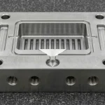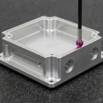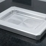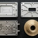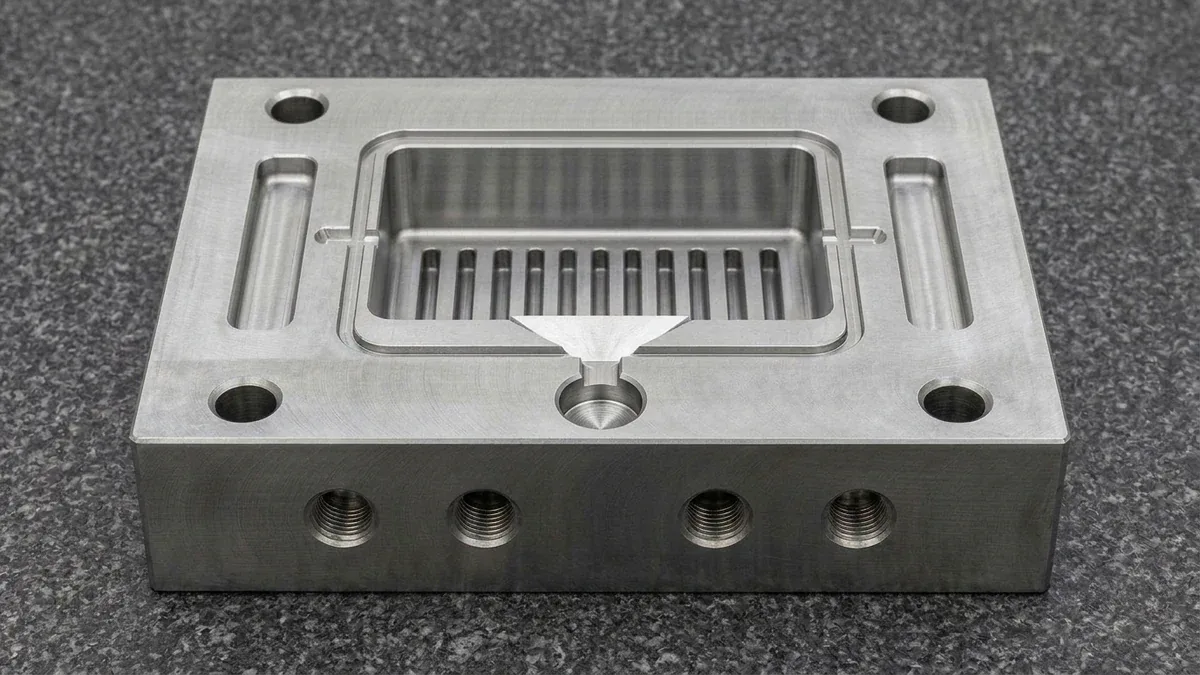
Die casting mold design directly governs structural density, internal porosity, surface finish, and tooling longevity in high-pressure die casting (HPDC). During each cycle, molten aluminum alloys like ADC12 and A380 at 650°C–680°C—or zinc alloys like Zamak 3 and Zamak 5 at 415°C–440°C—inject into steel cavities under 600 to 1,200 bar (60–120 MPa) intensification pressure.
When gating hydraulics, runner cross-sections, draft angles, or cooling circuits are improperly engineered, high-velocity liquid metal jets cause severe shop-floor defects. Turbulent flow separation entrains air pockets that form subsurface gas blisters during heat treatment or powder coating, while uncooled core pins suffer intermetallic iron-aluminum soldering (FeAl3 and Fe2Al5 welding), ejection galling, and thermal fatigue heat checking.
At our in-house mold shop, die-casting foundry, and precision CNC machining facility, we integrate mold-flow simulation with vacuum-hardened AISI H13 (SKD61 / 1.2344 ESR) and Uddeholm DIEVAR hot-work tool steels. Pairing 5-axis hard milling and Wire EDM mold fabrication (±0.005 mm) with high-speed 3-axis and 4-axis VMC post-machining (±0.010 to ±0.020 mm) ensures pressure-tight die-cast hardware.
Executive Summary & Engineering Takeaways (BLUF)
- Hot-Work Tool Steel Metallurgy (
44 to 50 HRC): Electro-Slag Remelted (ESR)AISI H13 (SKD61 / 1.2344 / 4Cr5MoSiV1),Uddeholm Orvar Supreme (8407), andUddeholm DIEVARinserts—vacuum-austenitized at1,020°C–1,030°Cand triple-tempered at560°C–610°Cto44–48 HRCfor aluminum/magnesium HPDC and46–50 HRCfor zinc HPDC (ASTM E18) with ferritic nitrocarburizing or duplex PVDAlCrN—deliver80,000 to 250,000 shotsfor aluminum and500,000 to 1,000,000+ shotsfor zinc. - Runner, Fan Gate & Chill Vent Hydraulics: Tapered trapezoidal runners with
10%–20%cross-sectional reduction feed converging/diverging fan gates (0.8 to 2.5 mmland thickness) at30 to 60 m/singate velocity within0.015 to 0.040 sfill time, paired with peripheral overflow wells and corrugated chill vents (0.12 to 0.18 mmgap). - Asymmetrical Draft Angles & Fillet Radii: Solidification shrinkage grips internal cores while pulling away from outer walls, requiring outer wall draft
α = 1.5° to 2.5°vs. inner core draftβ = 2.0° to 3.0°and cast fillet radiiR ≥ 1.5 mm. - Cooling Line Standoff (
D ≥ 2.5d): Gun-drilled cooling lines (d = 8–12 mm) positioned atD ≥ 2.5d (18 to 25 mm)from the cavity surface—supplemented by internal baffle/jet bubblers inside hot bosses—maintain200°C to 260°Cdie temperatures without thermal shock cracking. - Dual-Stage Tolerances: Dry air-blast 5-axis hard milling and Wire EDM hold
±0.005 mm (±0.0002″)on hardened H13 mold shut-off lands, while secondary post-machining on 3-axis and 4-axis VMCs holds±0.010 to ±0.020 mmon critical cast features (as-castISO 8062-3 DCTG 5–7 / CT5–CT6; general machinedISO 2768-mK).
Article Engineering Navigation
- 1. Which Hot-Work Tool Steels (H13, SKD61 & DIEVAR) Prevent Die Casting Heat Checking?
- 2. How Do Tapered Runners, Fan Gates, Overflows & Chill Vents Prevent Porosity?
- 3. How Do You Calculate Gate Area, Fill Time & Machine Clamping Force?
- 4. Why Do Die Casting Molds Require Asymmetrical Draft Angles & D ≥ 2.5d Cooling?
- 5. How Does 5-Axis Hard Milling of H13 Cores Differ from 3/4-Axis VMC Post-Machining?
- 6. How Are Die Casting Molds Qualified Through T1 Sampling & OES/CMM Inspection?
- 7. Frequently Asked Questions (FAQ) on Die Casting Mold Design
1. Which Hot-Work Tool Steels (H13, SKD61 & DIEVAR) Prevent Die Casting Heat Checking?
Selecting hot-work tool steel metallurgy is the structural foundation of high-pressure die casting mold design. Cold-chamber aluminum alloys (ADC12 / A380 at 650°C–680°C) and magnesium alloys (AZ91D at 640°C–670°C) subject cavity surfaces to extreme thermal shock, whereas hot-chamber zinc alloys (Zamak 3 / Zamak 5 at 415°C–440°C) impose lower thermal cyclic stress.
Our mold shop machines active core and cavity inserts from Electro-Slag Remelted (ESR) AISI H13 (SKD61 / DIN 1.2344 / 4Cr5MoSiV1), Uddeholm Orvar Supreme (8407), and Uddeholm DIEVAR verified to SEP 1614 spheroidized carbide microstructure standards. ESR refining eliminates non-metallic sulfide inclusions and micro-segregation bands that otherwise nucleate early thermal fatigue cracks.
After rough machining with a 0.30 to 0.50 mm grinding and hard-milling allowance, inserts undergo multi-stage vacuum heat treatment. Preheating at 650°C and 850°C precedes vacuum austenitizing at 1,020°C–1,030°C (1,868°F–1,886°F), followed by high-pressure nitrogen gas quenching (5–6 bar) and mandatory triple tempering at 560°C–610°C (1,040°F–1,130°F) to transform retained austenite into tough tempered martensite.
Per NADCA #207 and in-house die-casting shop standards, working hardness is matched to alloy thermal severity (ASTM E18). Aluminum and magnesium HPDC cavities are tempered to 44 to 48 HRC (high-wear gate/core inserts and zinc dies at 46 to 50 HRC) to balance Charpy V-notch impact toughness against thermal fatigue heat checking.
Pre-hardened P20 / 4140 (42CrMo4, 28–32 HRC), 718H (1.2738), and S50C steels are strictly restricted to A/B die shoes, holder plates, and ejector boxes—never molten aluminum cavities. Similarly, S136 (1.2083, 48–52 HRC) stainless steel is reserved for plastic injection molds due to its lower thermal conductivity and inferior thermal-shock fatigue resistance.
To prevent molten aluminum from soldering onto steel (FeAl3 and Fe2Al5), core pins undergo ferritic nitrocarburizing at 500°C–540°C (950–1,100 HV0.2 case per ASTM E384) or duplex PVD AlCrN coating. Likewise, SKD61 (H13) nitrided ejector pins combine a 650–700 HV wear-resistant surface with a tough 44–48 HRC core to prevent galling.
| Tool Steel Grade | Vacuum Heat Treatment & Hardness (ASTM E18) | Thermal Conductivity | Target Alloy & Melt Temp | Expected Shot Life |
|---|---|---|---|---|
| ESR AISI H13 (SKD61 / 1.2344 / 4Cr5MoSiV1) & Orvar Supreme (8407) | 1,020–1,030°C Quench + Triple-Tempered 560–610°C to 44–48 HRC (Cores 46–48 HRC) | 28.6 W/(m·K) | Cold-Chamber Al / Mg (ADC12, A380, AZ91D at 640°C–680°C) | 80,000 – 150,000 shots |
| Uddeholm DIEVAR (ESR Low-Si High-Mo Hot-Work Steel) | 1,020–1,030°C Quench + Triple-Tempered 560–610°C to 44–48 HRC (Gate/Core 46–50 HRC) | 31.0 W/(m·K) | High-Stress Structural Al (ADC12 / A380 / AlSi10Mg at 650°C–680°C) | 150,000 – 250,000 shots |
| ESR H13 / SKD61 + Ferritic Nitrocarburizing or Duplex PVD AlCrN | 46–50 HRC Matrix (44–48 HRC Ejector Core; 650–700 HV Ejector / 950–1,100 HV0.2 Core Pin) | 28.6 W/(m·K) | Hot-Chamber Zinc (Zamak 3 / Zamak 5 at 415°C–440°C), Al Core & Ejector Pins | 500,000 – 1,000,000+ shots (Zn) |
| Pre-Hardened P20 / 4140 (42CrMo4) / 718H (1.2738) Die Shoes | 28 – 32 HRC (Pre-Hardened & Stress-Relieved Holder Base) | 34.0 W/(m·K) | A/B Die Shoes, Holder Block, Ejector Housing & Locking Wedge Support | 500,000+ shots (Reusable Base) |
2. How Do Tapered Runners, Fan Gates, Overflows & Chill Vents Prevent Porosity?
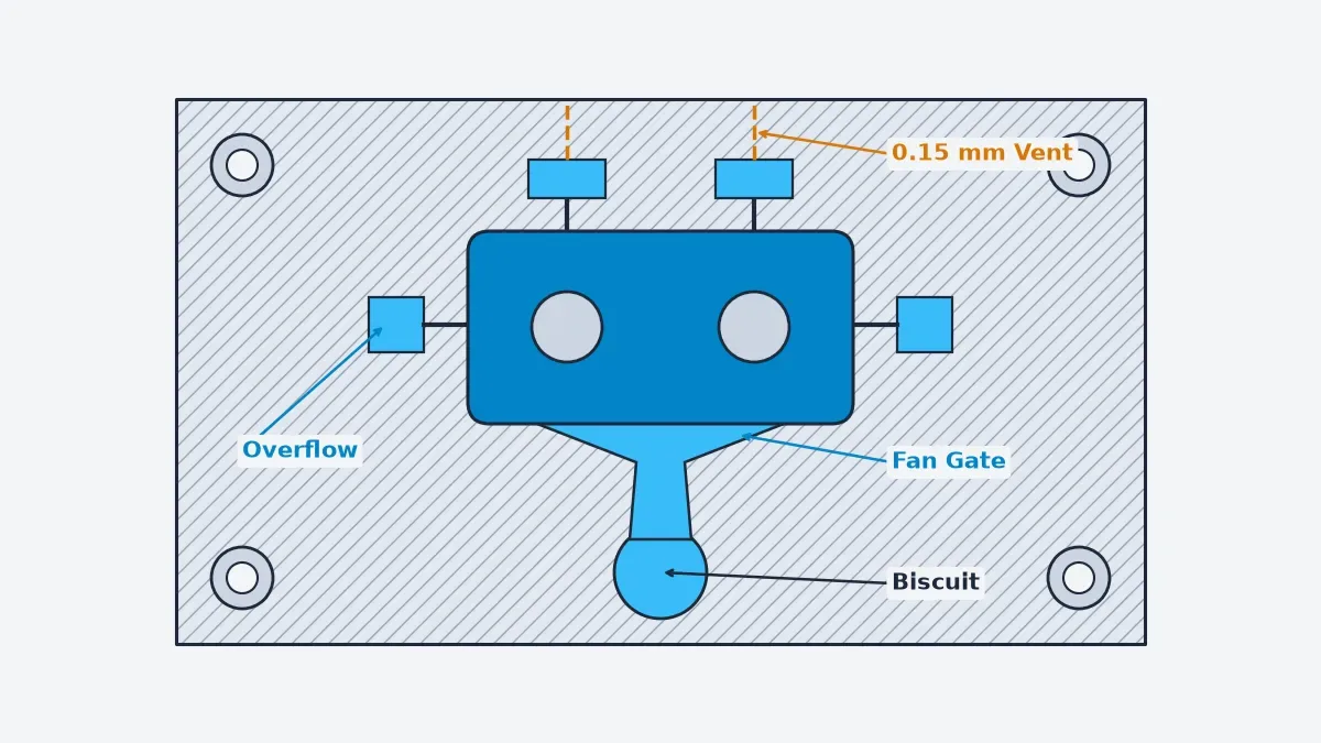
In high-pressure die casting, thin-wall cavity fill completes within 15 to 40 ms (0.015–0.040 s). Whether feeding a finned heatsink block via a front shot-biscuit pocket, straight runner, triangular fan gate, side overflow wells, and flush water ports—or a circular pump-scroll insert via diverging runners into chill vents—closed-front hydraulics prevent air entrapment.
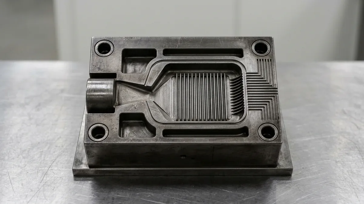
During first-phase slow approach (0.2 to 0.4 m/s), the cold-chamber plunger advances molten metal gently to push air out through the vents without curling a breaking wave inside the shot sleeve. Once liquid metal reaches the runner choke, second-phase high-speed shot acceleration (2.0 to 4.5 m/s plunger velocity) atomizes the stream across the cavity.
From the cylindrical shot biscuit—which maintains a 20 to 35 mm thickness to feed solidification shrinkage during third-phase intensification—the tapered trapezoidal runner undergoes a 10%–20% progressive cross-sectional reduction at each branch. Maintaining a converging hydraulic gradient prevents vena-contracta low-pressure eddies that would otherwise aspirate cavity gases into the melt stream.
At the cavity entry, a converging/diverging fan gate spreads the flow width while compressing depth into a 0.8 to 2.5 mm gate land (with a short 1.5 to 3.0 mm land length). This geometry accelerates the melt to 30 to 60 m/s ingate velocity for aluminum (35 to 55 m/s for zinc) while permitting clean trim-press degating.
Opposite the fan gate and behind cored bosses where split flow fronts knit together, peripheral overflow wells (sized at 15% to 35% of adjacent segment volume) capture the cold, oxidized leading metal front and die-lube residue. Downstream corrugated chill vents machined with a 0.12 to 0.18 mm zig-zag gap exhaust displaced air while instantaneously freezing molten flash.
| Hydraulic Element | Cold-Chamber Aluminum (ADC12 / A380) | Hot-Chamber Zinc (Zamak 3 / 5) | Primary Shop-Floor Defect Prevented |
|---|---|---|---|
| Shot Biscuit / Sprue Post & Sleeve Fill Ratio | 20–35 mm biscuit; 35%–55% cold-chamber sleeve fill ratio | Submerged gooseneck nozzle; tapered sprue pin (4°–6° taper) | Plunger wave air entrapment, pre-solidified cold flakes & shrinkage loss |
| Trapezoidal Main & Branch Runners | 10%–20% progressive area reduction; depth-to-width ratio 1:1.5 to 1:2.0 | 10%–15% progressive area reduction; polished radii R ≥ 3.0 mm | Vena-contracta cavitation eddies & turbulent air aspiration |
| Converging Fan Gate & Ingate Velocity (vg) | 0.8–2.5 mm gate thickness (1.5–3.0 mm land); vg = 30–60 m/s | 0.4–1.2 mm gate thickness (1.0–2.0 mm land); vg = 35–55 m/s | Cold shuts, flow lines, core-pin jet erosion (>65 m/s) & trim breakout |
| Peripheral Overflow Wells & Sub-Gates | 15%–35% of local segment volume; 0.6–1.2 mm overflow gate thickness | 10%–25% of local segment volume; 0.4–0.8 mm overflow gate thickness | Knit-line cold laps, trapped die-lube residue & distal edge cold spots |
| Corrugated Chill Vents & Parting Vents | 0.12–0.18 mm zig-zag chill vent gap (vent area = 15%–25% of Ag) | 0.06–0.12 mm vent gap (vent area = 10%–20% of Ag) | Compressed air back-pressure porosity, blistering & parting-line flash blow |
3. How Do You Calculate Gate Area, Fill Time & Machine Clamping Force?
Before cutting H13 tool steel, our DFM engineers calculate ingate cross-sectional area (Ag) via continuity and PQ² hydraulics, cold-chamber shot sleeve fill ratio (ηfill), and machine clamping force (Fclamp). Quantitative sizing prevents premature freezing while ensuring intensification pressure peaks do not blow open the parting plane or hydraulic side-core sliders.
How Are Ingate Area, Shot-Sleeve Fill Ratio & Clamping Tonnage Calculated?
- Inner Gate Cross-Sectional Area (PQ² / Continuity Equation):
Ag = mshot ÷ (ρm × tf × vg)— wheremshotis cavity shot mass passing through the gate (g, casting plus overflows),ρmis molten alloy density (2.50 g/cm³for liquid aluminum at660°C;2.70 g/cm³solidADC12 / A380),tfis thin-wall cavity fill time (0.015 to 0.040 s), andvgis ingate velocity (30 to 60 m/s = 3,000 to 6,000 cm/s). - Cold-Chamber Shot-Sleeve Fill Ratio:
ηfill = [Vtotal ÷ ((π ÷ 4) × Ds2 × Ls)] × 100%— whereVtotalis total poured molten volume including biscuit and runners (cm³),Dsis cold-chamber plunger bore diameter (mmorcm), andLsis active sleeve length beneath the pour hole (targetηfill = 40% to 55%, preventing air-entrapment wave cresting below40%). - Machine Clamping Tonnage:
Fclamp = k × (Aproj × Pspec) ÷ 10,000— whereAprojis total projected parting-plane area including casting, biscuit, runners, and overflows (cm²converted tomm²via1 cm² = 100 mm², soFtheoretical = (Aproj, cm² × Pspec, MPa) ÷ 100in metric tons at10,000 N ≈ 1 ton / 10 kN),Pspecis specific intensification pressure (60–120 MPa/600–1,200 bar), and safety factork = 1.20–1.30. - Angled Guide-Pin Slide Core Stroke & Locking Wedge Angle:
S = Lundercut + candLpin = S ÷ sin(θ)(with heel locking wedge angleβ = θ + 2° to 3°), whereLundercutis lateral undercut depth (mm),cis safety clearance (2.0 to 3.0 mm),Lpinis active guide-pin working length at inclinationθ(18° to 22°), andβis the steeper locking wedge angle (20° to 25°).
Worked Example 1—Inner Gate Area (ADC12 Housing): With mshot = 1,080 g and molten density ρm = 2.50 g/cm³, gate-fed volume Vshot = 1,080 ÷ 2.50 = 432 cm³ (432,000 mm³). At tf = 0.024 s and vg = 45 m/s: Ag = 1,080 ÷ (2.50 × 0.024 × 4,500) = 4.00 cm² = 400 mm² (tg = 1.6 mm, wg = 250 mm fan gate).
Worked Example 2—Shot-Sleeve Fill Ratio: Adding the 370 g (148 cm³) biscuit and runner yields 1,450 g total poured shot (Vtotal = 580 cm³). With plunger bore Ds = 80.0 mm and active length Ls = 250.0 mm (Vsleeve = 1,256.6 cm³), ηfill = 580 ÷ 1,256.6 = 46.2%, preventing wave-cresting air entrapment below 40%.
Worked Example 3—Clamping Tonnage: With projected parting area Aproj = 580 cm² (58,000 mm²), intensification pressure Pspec = 75 MPa (750 bar), and safety factor k = 1.20: theoretical opening force Ftheoretical = (58,000 × 75) ÷ 10,000 = 435 tons (4,350 kN), yielding Fclamp = 1.20 × 435 = 522 tons (5,220 kN) for a 650T–800T Buhler or LK machine.
Worked Example 4—Side-Core Slide Stroke: With undercut Lundercut = 23.0 mm and clearance c = 3.0 mm, stroke S = 23.0 + 3.0 = 26.0 mm. At θ = 20°, pin length Lpin = 26.0 ÷ sin(20°) = 76.02 mm (85 mm standard pin) with a β = 22°–23° locking wedge.
When matching the mold to a 650T–800T cold-chamber press, our tooling engineers verify the machine’s PQ² hydraulic curve. At a 432 cm³ gate-fed volume and 0.024 s fill time, flow rate Q = 432 ÷ 0.024 = 18,000 cm³/s (18.0 L/s), requiring a second-phase plunger speed of vp = 18,000 ÷ 50.27 = 3.58 m/s.
4. Why Do Die Casting Molds Require Asymmetrical Draft Angles & D ≥ 2.5d Cooling?
Because solidifying aluminum contracts linearly by 0.5%–0.7% (0.005–0.007 mm/mm), castings shrink away from outer cavity walls while gripping internal standing cores. Consequently, die casting mold design requires asymmetrical draft angles: outer wall draft α = 1.5°–2.5° versus steeper inner core draft β = 2.0°–3.0° (3.0°–5.0° on deep ribs) to prevent soldering and ejection galling.
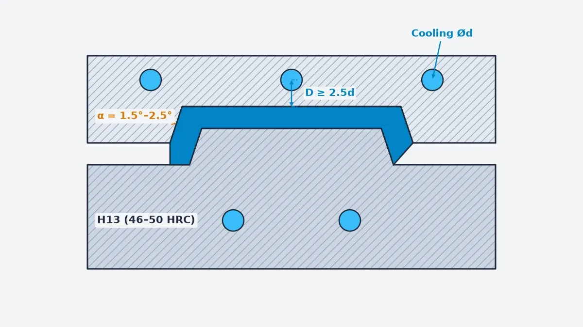
Specifying cast fillet radii of R ≥ 1.5 mm (ideally R = 0.5t to 1.0t) at rib-to-wall junctions eliminates sharp H13 steel corners that overheat and erode under 45 m/s metal impingement. Uniform wall thickness (2.0 to 3.5 mm for aluminum; 1.0 to 2.5 mm for zinc) prevents isolated heavy thermal masses that cause internal shrinkage voids.
Thermal equilibrium is maintained at 200°C–260°C for aluminum (160°C–200°C for zinc) via independent gun-drilled water and hot-oil circuits (d = 8–12 mm). Every cooling channel respects a cavity-wall standoff of D ≥ 2.5d (18–25 mm) and a center pitch of P = 3.0d–4.0d so cyclic thermal stress never cracks the H13 block.
For hot bosses where straight gun-drilled lines cannot reach, we integrate coaxial stainless-steel jet bubblers (⌀4.0–6.0 mm) and SKD61 nitrided ejector pins (650–700 HV surface, 44–48 HRC core). For lateral undercuts, angled slide cores ride on self-lubricating bronze wear plates with 20°–25° locking wedges (2°–3° steeper than 18°–22° guide pins) to resist injection blowback.
5. How Does 5-Axis Hard Milling of H13 Cores Differ from 3/4-Axis VMC Post-Machining?
Hardware buyers must distinguish between hardened mold manufacturing tolerances and secondary casting post-machining tolerances. In our toolroom, vacuum-hardened 44–50 HRC H13 and DIEVAR inserts are finished via Simultaneous 5-Axis Hard Milling, Surface Grinding, CNC Sinker EDM, and Wire EDM to hold ±0.005 mm (±0.0002″) on shut-off lands, slide ways, and core pin bores.
When hard milling 44–48 HRC (Al) or 46–50 HRC (Zn) H13 steel with AlTiN / AlCrN solid carbide end mills (Vc = 120–180 m/min, fz = 0.03–0.06 mm/tooth, ae = 0.05–0.15 mm), machinists strictly use high-pressure dry air blast or MQL. Flood water coolant is prohibited because thermal quenching cracks hot carbide edges and H13 surfaces.
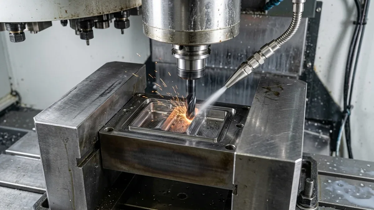
For deep blind heatsink ribs and narrow boss slots unreachable by rotating cutters, CNC Sinker EDM with fine-grain graphite or copper electrodes performs multi-stage skim orbiting to Ra 0.4 µm. Subsequent mechanical stoning, stress-relief tempering, and gas nitrocarburizing or PVD (CrN / AlCrN) remove the brittle tensile EDM white recast layer before T1 sampling.
Conversely, raw die-castings hold general dimensional tolerances per ISO 8062-3 DCTG 5–7 (CT5–CT6, ±0.10 to ±0.25 mm for aluminum; DCTG 4–6 / CT4–CT5 or ±0.07 to ±0.15 mm for zinc). Because rapid solidification against the cooled H13 wall forms a dense 0.5–0.8 mm chilled skin, CNC stock is capped at 0.4 to 0.8 mm per face.
Machining deeper than 1.0 mm breaches this chilled outer skin and exposes subsurface microporosity on O-ring faces or threaded bosses. Using hydraulic fixtures on our high-speed 3-axis and 4-axis VMCs, we skim datum faces and bore bearing seats to ±0.010 to ±0.020 mm (ISO 2768-mK), holding flatness ⏥ 0.020 mm and true position ⌖ ⌀0.025 mm.
| DFM / Tolerance Parameter | Cold-Chamber Aluminum (ADC12 / A380) | Hot-Chamber Zinc (Zamak 3 / Zamak 5) | Governing Standard / Shop Process |
|---|---|---|---|
| Linear Mold Shrinkage Allowance | 0.50% – 0.70% (0.005–0.007 mm/mm) | 0.60% – 0.80% (0.006–0.008 mm/mm) | Cavity CAD Scaling Factor |
| Outer Wall Draft (α) vs. Inner Core Draft (β) | α = 1.5°–2.5° | β = 2.0°–3.0° (Ribs 3°–5°) | α = 0.5°–1.0° | β = 1.0°–1.5° (Ribs 1.5°–2.5°) | Solidification Shrinkage Grip Relief |
| Cast Fillet Radii & Cooling Standoff (D) | R ≥ 1.5 mm | D ≥ 2.5d (18–25 mm; 200–260°C die) | R ≥ 0.8 mm | D ≥ 2.0d (15–20 mm; 160–200°C die) | Thermal Fatigue & Soldering Prevention |
| Hardened H13 Mold Shut-Off & Core Pins | ±0.005 mm (±0.0002″); Shut-off ⏥ 0.005 mm | ±0.005 mm (±0.0002″); Shut-off ⏥ 0.005 mm | Dry Air-Blast 5-Axis Hard Milling, Sinker EDM & Wire EDM |
| General As-Cast Part Tolerance | ±0.10 mm to ±0.25 mm (0.4–0.8 mm CNC stock) | ±0.07 mm to ±0.15 mm (0.3–0.6 mm CNC stock) | ISO 8062-3 DCTG 5–7 (CT5–CT6 Al; DCTG 4–6 Zn) |
| Secondary CNC Post-Machined Features | ±0.010 to ±0.020 mm; Flatness ⏥ 0.020 mm; ⌖ ⌀0.025 mm | ±0.010 to ±0.020 mm; Flatness ⏥ 0.020 mm; ⌖ ⌀0.025 mm | High-Speed 3-Axis & 4-Axis VMC (ISO 2768-mK) |
6. How Are Die Casting Molds Qualified Through T1 Sampling & OES/CMM Inspection?
Integrating mold design, vacuum heat treatment, HPDC trials, and CNC post-machining under one roof in our in-house facility eliminates multi-vendor handoff delays. Every mold undergoes a structured four-gate qualification workflow before batch release:
- OES Alloy, SEP 1614 Microstructure & Vacuum Heat-Treatment Gate: Incoming ESR
AISI H13 (1.2344 / SKD61)andUddeholm DIEVARblocks—plusADC12 / A380 / Zamakmelt lots—are verified via Optical Emission Spectroscopy (OES),SEP 1614spheroidized carbide microstructure grading, andSEP 1921ultrasonic flaw detection, followed by post-temperingASTM E18Rockwell hardness testing (44–48 HRCfor Al;46–50 HRCfor Zn) andASTM E384Vickers verification (950–1,100 HV0.2on cavity cores;650–700 HVsurface with44–48 HRCcore onSKD61nitrided ejector pins). - Hard-Milled Insert & Spotting Press Assembly Gate: Finished cavity inserts, side-core sliders, and chill vents are inspected on our Zeiss Bridge CMM (
±0.005 mm), spotted in a die-spotting press to verify≥ 85%–90%Prussian-blue contact bearing across parting lands and locking wedges, and hydrostatically pressure-tested across all cooling circuits at8.0–10.0 barfor30 minutes. - T1 Short-Shot & Intensification Window Qualification Gate: During T1 press trials (
180 to 1,250-toncold-chamber and88 to 280-tonhot-chamber machines), engineers run progressive30%, 60%, and 90%short-shot fills without intensification to validate gate balance and overflow capture, then lock in third-phase intensification pressure (60–120 MPa) and die thermal equilibrium (200°C–260°C). - Casting Density, Metallographic Cross-Section & Post-Machined CMM Gate: T1 castings undergo Archimedes water-displacement density testing (
≥ 2.68–2.72 g/cm³onADC12), sectioned metallographic cross-section polishing and optical microscopy across thick bosses and O-ring tracks to verify pore-free skin integrity, air/water pressure-decay leak testing at3.5–6.0 bar, and full dimensional qualification using our20°C ± 1°CZeiss Bridge CMM, 2.5D Optical Video Measuring System (VMS), Mitutoyo 3-point bore micrometers, Class ZZ GO/NO-GO pin gauges, ISO 1502 / ASME B1.2 thread gauges, and ISO 4287 contact stylus profilometer (Ra / Rz).
All stated lead times below represent Ex-Factory Production & Inspection Turnaround, strictly separate from 3 to 5 business days international express air shipping (DHL / FedEx / UPS):
- DFM & Mold-Flow Analysis (
Within 24 Hours;24 to 48 Hoursfor Complex Multi-Slide Tooling): Gate/runner hydraulic simulation, parting-line layout, draft review, and CNC post-machining stock allocation (0.4 to 0.8 mm). - Rapid CNC Machined Functional Prototypes (
4 to 8 Business DaysAs-Machined;7 to 12 Business DaysSurface-Finished Ex-Factory): Pre-tooling billet aluminum (6061-T6 / ADC12 equivalent) and zinc prototypes machined on 3/4/5-axis CNC centers to validate fit before cutting H13 steel. - Die-Casting Mold & T1 Samples (
18 to 35 Business DaysEx-Factory): Complete H13/DIEVAR insert machining, vacuum heat treatment and triple tempering (44–50 HRCperASTM E18), dry air-blast 5-axis hard milling, EDM shut-off spotting, and T1 sample shots. - Low-to-Mid Volume Production Casting, 3/4-Axis VMC Post-Machining & Metrology (
7 to 30 Business DaysEx-Factory): Batch casting, trim-press degating, CNC post-machining, chromate conversion (MIL-DTL-5541 / SurTec 650) or powder coating (ASTM B117verified),3.5–6.0 barpressure-decay leak testing, and20°C ± 1°Cclimate-controlled Zeiss Bridge CMM inspection (ISO 1101/ASME Y14.5).
Related Precision Manufacturing & Tooling Engineering Guides
- High-Speed 3-Axis & 4-Axis CNC Post-Machining Services — Precision skimming of die-cast sealing faces, O-ring grooves, and bearing bores to ±0.010 mm.
- High-Pressure Die Casting Process Guide — Cold-chamber aluminum vs. hot-chamber zinc alloy selection, intensification pressure phases, and cycle optimization.
- Shrinkage in Metal Die Casting: Causes & DFM Solutions — Controlling solidification contraction, hot spots, and internal porosity in ADC12 and A380 castings.
7. Frequently Asked Questions (FAQ) on Die Casting Mold Design
Molten ADC12 and A380 aluminum injects at 650°C–680°C and 30–60 m/s, subjecting cavity surfaces to cyclic thermal shock. Vacuum-hardened ESR H13 (SKD61/1.2344) and Uddeholm DIEVAR triple-tempered at 560°C–610°C to 44–48 HRC for aluminum and 46–50 HRC for zinc prevent heat checking across 80,000–250,000+ shots.
During solidification, linear thermal contraction of 0.5%–0.7% pulls the casting away from outer cavity walls, allowing α = 1.5°–2.5° outer draft. Conversely, internal bosses and pockets shrink tightly onto standing H13 cores, requiring β = 2.0°–3.0° inner draft to prevent soldering and ejection galling.
A 10%–20% progressive runner area reduction prevents air entrainment before the 0.8–2.5 mm fan gate injects metal at 30–60 m/s. Peripheral overflow wells trap the cold oxidized leading metal front, while corrugated chill vents with a 0.12–0.18 mm gap exhaust cavity air and freeze flash instantaneously.
Simultaneous 5-axis hard milling and Wire EDM hold ±0.005 mm on hardened H13 mold shut-off lands and core pins. Raw castings follow ISO 8062-3 DCTG 5–7, while secondary 3/4-axis VMC machining of 0.4–0.8 mm stock holds ±0.010 to ±0.020 mm on sealing faces and bores (ISO 2768-mK).
Ready to Engineer Your Custom Die Casting Tooling & CNC Machined Castings?
Upload your 3D CAD models (STEP, IGES, or SolidWorks) and 2D GD&T engineering drawings for a comprehensive mold-flow gating review, H13/DIEVAR tooling quotation, and secondary CNC post-machining DFM analysis from our in-house engineering team.
Upload CAD for Engineering DFM & Tooling Quote →