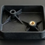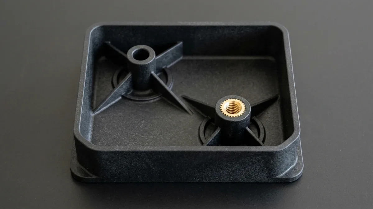
In thermoplastic enclosure engineering, screw boss design injection molding rules govern the critical balance between fastener pull-out retention and Class-A cosmetic surface integrity. Screw bosses serve as internal cylindrical standoffs that locate printed circuit boards (PCBs), align sub-assemblies, and anchor thread-forming screws or knurled brass inserts across industrial, automotive, and medical housings.
When a cylindrical boss intersects an enclosure wall without strict geometric control, localized polymer mass creates an insulated thermal hot spot. As the surrounding thin walls solidify against water-cooled mold steel, the molten core beneath the boss root contracts inward, pulling the outer cosmetic skin into a visible sink mark crater.
At our in-house plastic injection molding and tooling facility, our engineers evaluate every boss intersection during pre-tooling Design for Manufacturability (DFM) reviews. Pairing high-speed 3-axis and 4-axis CNC machining for functional plastic prototypes with hardened steel mold execution eliminates cosmetic sink, core pin deflection, and hoop splitting before T1 sampling.
Executive Summary & Engineering Takeaways (BLUF)
- Sink-Free Wall Ratio (Wboss = 0.50T–0.60T): Cap Class-A boss root thickness at 0.60T for amorphous resins (ABS, PC, PC-ABS, PMMA at 0.4%–0.7% linear mold shrinkage), 0.50T for PA66, and 0.45T–0.50T for high-shrink semi-crystalline grades (POM, PP, PE at 1.5%–2.2% linear shrinkage; ≤ 0.65T–0.70T on hidden non-cosmetic interiors).
- Self-Tapping Sizing, Lamé Hoop Stress & Base Coring Moat: Thread-forming screws (30° PT / Delta PT / Plastite) require OD = 2.0d–2.5d, pilot ID = 0.80d–0.85d (0.85d–0.90d in glass-filled resins), a 0.5–0.8 mm lead-in counterbore, and a 0.30T–0.50T deep annular volcano coring moat keeping the root wall ≤ 0.60T.
- Gusset Ribs, Fillets & ESC Prevention: Brace freestanding bosses with 3 to 4 symmetric triangular gusset ribs (trib = 0.50T–0.60T, 0.5°–1.5° draft) and a 0.25T–0.40T root fillet (min 0.50 mm); detach bosses 1.5T–2.5T (≥ 2.0T, min 3.0 mm) from sidewalls via a 0.50T bridge rib, and ban methacrylate threadlockers on PC or PC-ABS (ISO 22088-3 ESC risk).
- C3604 / C36000 Brass Inserts: Heat-staked and ultrasonic knurled inserts (M2–M6) require a tapered or stepped receiver bore held to +0.05 / −0.00 mm (+0.002″ / −0.000″), a straight lead-in counterbore, a 1.0–1.5 mm bottom flash-relief pocket, and OD = 2.0×–2.5× insert OD (2.2×–2.5× insert OD recommended for notch-sensitive amorphous PC and ABS).
- Height Limits, Draft & Sleeve Ejection: Limit total boss height to H ≤ 2.5×–3.0× OD, specify 0.5°–1.5°/side outer draft and 0.25°–0.50°/side core pin draft (L/d ≤ 5.0), and pair hardened S136 / H13 (48–52 HRC) core pins with 360° SKD61 nitrided ejector sleeves on bosses taller than 5.0–8.0 mm.
Article Engineering Navigation
- 1. What Is the Sink-Free Boss Wall Ratio (0.50T–0.60T) & Shrinkage Physics?
- 2. How Do You Size Self-Tapping Bosses (OD = 2.0d–2.5d) & Base Coring?
- 3. How Do Root Fillets (0.25T–0.40T), Gusset Ribs & Stand-Offs Prevent Cracking?
- 4. How Do You Design Bosses for C3604 Brass Inserts (Heat Staking vs. Overmolding)?
- 5. What Are the Boss Height Limits (≤ 2.5×–3.0× OD), Draft & Ejection Rules?
- 6. How Do We Validate Boss Tooling, Metrology & Ex-Factory Lead Times?
- 7. Technical Engineering FAQ
1. What Is the Sink-Free Boss Wall Ratio (0.50T–0.60T) & Shrinkage Physics?
The primary cosmetic failure in screw boss design injection molding is an exterior sink mark depression directly opposite the boss base. While linear mold shrinkage measures 0.4% to 2.2% (0.004–0.022 mm/mm) for dimensioning cavity steel, molten thermoplastics undergo 6% to 18% volumetric melt contraction as they cool from processing temperature down to mold ejection temperature.
Solidification lag at the boss-to-wall T-junction is governed by one-dimensional Fourier heat conduction: tcool = [Dhot2 ÷ (π2 · αth)] · ln[(4 ÷ π) · (Tmelt − Tmold) ÷ (Teject − Tmold)]. Because cooling time scales with the square of the inscribed hot-spot circle diameter (tcool ∝ Dhot2), thick boss intersections stay molten long after the gate freezes.
When an uncored boss wall exceeds 0.80T or merges into an enclosure wall (T), the root inscribed hot-spot circle swells to Dhot ≈ 1.50T, requiring 2.25× longer cooling time than the 1.00T wall. In a 2.50 mm PC-ABS wall (αth = 0.10 mm2/s), wall solidification takes 11.40 s, whereas a 3.75 mm (1.50T) root takes 25.64 s.
As illustrated in the cross-section DFM schematic below, capping the boss wall at 0.60T (1.50 mm) with a 0.25T root fillet and a triangular gusset rib shrinks the inscribed hot-spot circle to Dhot = 1.12T (2.80 mm), cutting root cooling time to 14.30 s and preventing 0.08–0.15 mm exterior sink marks.
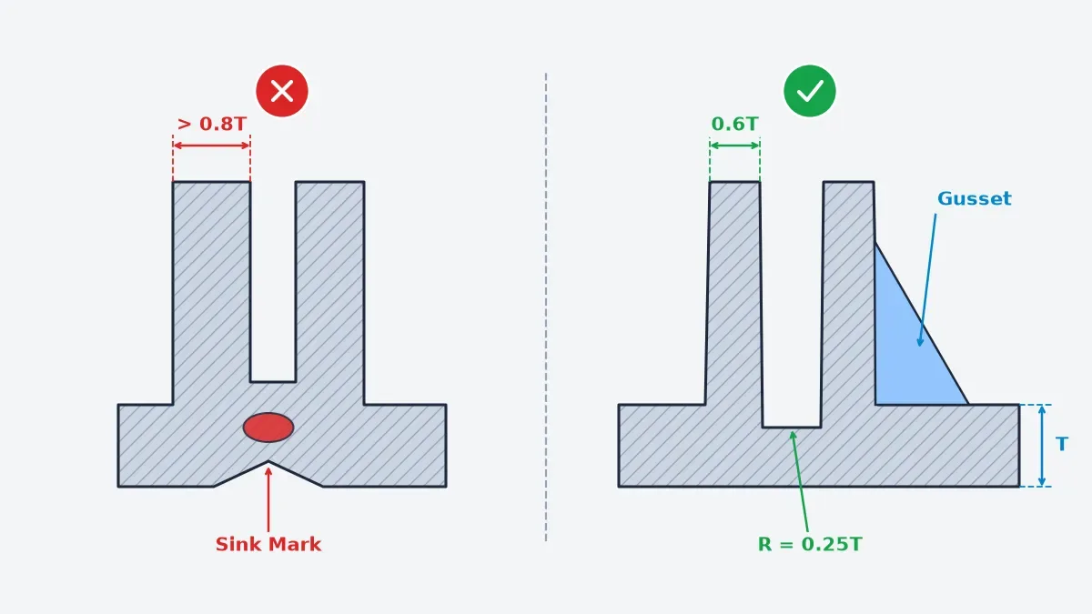
To prevent visible depressions on glossy (SPI A-2 / B-1) or fine-textured (VDI 3400 Ref 18–27) Class-A exteriors, cap root wall thickness at 0.60T for amorphous resins (ABS, PC, PC-ABS, PMMA at 0.4%–0.7% shrinkage), 0.50T for PA66, and 0.45T–0.50T for high-shrink semi-crystalline PP, PE, and POM (1.5%–2.2% shrinkage).
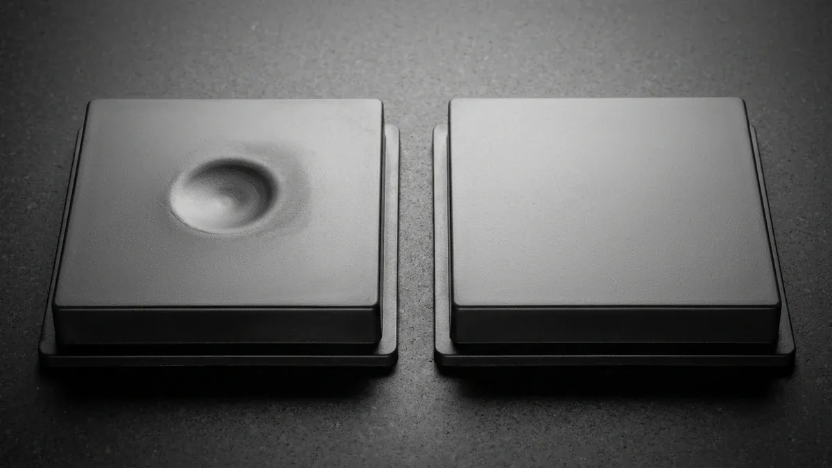
On hidden non-cosmetic structural interiors where minor aesthetic witness marks are permissible, engineers may extend the boss root ratio up to 0.65T–0.70T. The side-by-side cosmetic test plaques below demonstrate how an uncored heavy internal boss (>0.80T) pulls a deep circular exterior sink crater, whereas a cored 0.60T gusseted boss preserves a completely flat Class-A satin exterior.
2. How Do You Size Self-Tapping Bosses (OD = 2.0d–2.5d) & Base Coring?
Thread-forming screws for thermoplastics (such as 30° flank-angle PT / Delta PT and trilobular Plastite profiles, unlike 60° machine screws that cut polymer chains) cold-flow material without generating notch-sensitive stress risers. Driving the screw induces radial pressure (Pi), subjecting the boss barrel to tensile hoop stress per the Lamé thick-walled cylinder equation:
At the inner bore surface (r = ri), peak tangential hoop stress equals σθ,max = Pi · (DOD2 + dID2) ÷ (DOD2 − dID2) = Pi · (k2 + 1) ÷ (k2 − 1), where k = OD/ID. Resisting longitudinal hoop splitting and viscoelastic creep relaxation requires an outer barrel diameter of OD = 2.0d to 2.5d.
Specify a core-pin pilot bore of ID = 0.80d–0.85d for amorphous ABS, PC, and PC-ABS, 0.82d–0.88d for semi-crystalline PA66 and POM, and 0.85d–0.90d for stiff 30% glass-filled PA66-GF30 and PBT-GF30, with engagement depth Leng = 2.0d–2.5d. Add a 0.50–0.80 mm deep × ⌀ 1.05d lead-in counterbore to prevent first-thread splitting.
How Does an Annular Volcano Coring Moat Prevent Sink Marks Under a 2.0d–2.5d Boss?
When a self-tapping screw’s required 2.0d–2.5d barrel wall exceeds 0.60T on thin-walled housings, engineers resolve the conflict by machining an annular volcano coring moat (“crater-saver” recessed pocket) around the boss base. Sizing the moat depth at hmoat = 0.30T to 0.50T necks the root wall intersection down to ≤ 0.50T–0.60T while the upper barrel retains full 2.0d–2.5d hoop thickness.
📐 Worked Calculation: M3.0 Self-Tapping Boss, Lamé Hoop Stress & Pull-Out Torque in a 2.50 mm PC-ABS Wall
Sizing a sink-free boss in a PC-ABS housing (T = 2.50 mm / 0.0984″, tensile yield σy = 50.0 MPa, safe hoop limit 36.0 MPa, shear strength τpoly = 29.0 MPa) for an M3.0 PT screw (ds = 3.00 mm / 0.1181″) under Pi = 18.0 MPa (2.61 ksi) radial driving pressure:
- Pilot Bore, Cored 0.60T Root & Upper Barrel OD: Pilot bore dhole = 0.82 ds = 2.46 mm (0.0969″) (or 0.80 ds = 2.40 mm). At a sink-free tboss = 0.60T = 1.50 mm (0.0591″) cored root, DOD,root = 2.46 + 2(1.50) = 5.46 mm (1.82 ds); widening the upper barrel above the base moat to DOD = 2.20 ds = 6.60 mm (0.2598″) gives a 2.07–2.10 mm (0.84T) upper wall.
- Lamé Peak Hoop Stress (0.60T Cored Root & 6.00 mm Barrel vs. Undersized 4.50 mm Boss): For a 6.00 mm (2.0ds) barrel with dhole = 2.45 mm (radial interference δ = 0.275 mm, secant modulus Es = 1,750 MPa, driving pressure Pi = 19.41 MPa), diameter ratio K = 6.00 ÷ 2.45 = 2.449 gives (K2 + 1) ÷ (K2 − 1) = 1.400 and σθ,max = 19.41 × 1.400 = 27.17 MPa (< 36.0 MPa PC-ABS craze limit) (matching the 0.60T cored root DOD = 5.46 mm, dhole = 2.46 mm at 18.0 MPa × 1.5094 = 27.17 MPa, dropping to 23.49 MPa at 6.60 mm and 22.50 MPa at 7.20 mm). Conversely, an undersized OD = 4.50 mm (K = 1.837) boss spikes hoop stress to σθ,max = 46.8 MPa (> 36.0 MPa), causing weld-line splitting.
- Crater-Saver Base Coring Moat: Machining a 0.57–0.65 mm radial × 1.00 mm deep (0.40T) annular volcano moat around the 6.60 mm barrel base necks the root wall intersection down to tb = 1.45–1.50 mm (0.58T–0.60T / 60%), braced by four 1.25 mm (0.50T) triangular gusset ribs—shrinking the root inscribed circle to Dinscribed = 1.12T = 2.80 mm (at r = 0.25T) or 1.38T = 3.45 mm (at r = 0.35T) versus an un-cored 5.80 mm (232% T) solid boss.
- Counterbore & Blind Core Pin L/d: 0.80 mm × ⌀ 3.15 mm (1.05ds) top counterbore + 6.60 mm (2.2ds) thread engagement + 1.00 mm tip clearance = 8.40 mm (0.3307″) bore depth, giving core pin slenderness L/dID = 8.40 ÷ 2.40 = 3.50 ≤ 5.0 (8.40 ÷ 2.46 = 3.41 ≤ 5.0) and boss height ratio H/DOD = 8.40 ÷ 6.60 = 1.27 ≤ 2.5.
- Axial Pull-Out Force & Tightening / Stripping Torque Window: Using cylindrical thread-stripping area Ashear ≈ (π ÷ √3) · ds · Leng = 1.8138 × 3.00 × 6.60 = 35.91 mm2 (0.0557 in2), pull-out force Fstrip = τpoly · Ashear = 29.0 MPa × 35.91 mm2 = 1,041.5 N (1.04 kN / 234.1 lbf); ultimate tightening/stripping torque Tdrive ≈ 0.2 · Fpreload · ds = 0.62–0.70 N·m (5.5–6.2 in·lbf) (initial drive torque 0.18 N·m, safe seating torque 0.40–0.45 N·m). Similarly, an M4 C3604 brass insert (ds = 6.30 mm, Leng = 5.00–5.40 mm in PC-ABS, τpoly = 28.0–29.0 MPa, Ashear = 35.91 mm2) achieves Fstrip = 1,041.5 N (≈ 1.04 kN).
3. How Do Root Fillets (0.25T–0.40T), Gusset Ribs & Stand-Offs Prevent Cracking?
Sharp 90° internal corners at the boss base concentrate cantilever bending and drop-shock stresses while restricting polymer melt flow into the core pin cavity. Specify a controlled root fillet radius of R = 0.25T to 0.40T (up to 0.50T max; 0.50–1.00 mm / 0.020″–0.039″) to distribute shear loads without inflating the root thermal sphere.
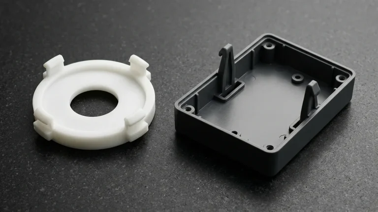
Rather than thickening the cylindrical boss barrel to resist lateral torque and vibration, reinforce freestanding bosses with 3 to 4 symmetric triangular gusset ribs. Size each gusset rib at trib = 0.50T to 0.60T at its base, tapering at 0.5° to 1.5° per side up to 80%–90% of the boss height to stiffen the column and aid melt flow.
Never merge a screw boss into an outer sidewall, which swells the hot-spot circle to Dhot = 1.50T (3.75 mm) and leaves fragile steel feather edges. Detach the boss 1.5T–2.5T (≥ 2.0T / 5.00 mm, min 3.0 mm) inboard and link it with a 0.50T (1.25 mm) bridge rib, shrinking the sidewall junction to Dhot = 1.08T (2.70 mm).
On amorphous PC, ABS, and PC-ABS enclosures, strictly forbid anaerobic methacrylate metal threadlockers (such as medium/high-strength liquid threadlockers) and ketone or ester solvents on stressed bosses. Combined with residual molding stress and Lamé hoop tension, these chemicals trigger catastrophic environmental stress cracking (ESC per ISO 22088-3) within hours; specify dry nylon-patch screws or C3604 brass inserts.
4. How Do You Design Bosses for C3604 Brass Inserts (Heat Staking vs. Overmolding)?
When hardware assemblies require 50+ repeated field-servicing cycles, sustained vibration resistance, or pull-out torque exceeding plastic shear limits, engineers specify C3604 / C36000 free-cutting brass diamond-knurled threaded inserts turned on our CNC Swiss lathes. Opposing helical diamond knurls resist rotational torque-out while horizontal annular undercut grooves lock against axial pull-out.
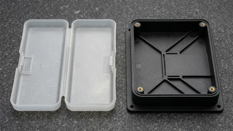
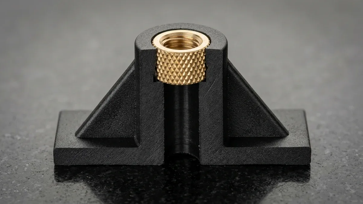
Post-molding Thermal Heat Staking (using a temperature-controlled heated tip at 20°C–40°C above Tg or Tm) and Ultrasonic Insertion (20–40 kHz horn vibration) press the brass insert into a pre-molded receiver bore. As shown in the destructive cutaway below, localized polymer melt flows fully into the knurl valleys and annular undercuts before solidifying into a zero-backlash mechanical lock.
Per PEM SI® and GE Plastics DFM guidelines, mold a tapered (1°–8°) or stepped receiver bore 0.15–0.25 mm (0.006″–0.010″) smaller than the insert knurl OD, holding bore tolerance to +0.05/−0.00 mm (+0.002″/−0.000″). Add a 0.50–0.80 mm straight top counterbore to seat the unknurled pilot flange concentrically without surface volcano flash.
Extend the blind receiver bore 1.0–1.5 mm (0.040″–0.060″) deeper than the brass insert length so a bottom flash-relief pocket traps displaced resin away from internal threads. Size the boss barrel at OD = 2.0×–2.5× Dinsert: use 2.0× Dinsert in ductile PA66, and 2.2×–2.5× Dinsert (with a 0.30T–0.50T base moat) in notch-sensitive PC, ABS, and PC-ABS.
For high-load structural joints requiring 100+ service cycles, Vertical In-Mold Overmolding encapsulates blind-end knurled inserts directly on core pins during injection. Pre-heating brass inserts to 80°C–120°C (176°F–248°F) and maintaining a radial wall of ≥ 0.50×–0.75× Dinsert (OD = 2.0×–2.5× Dinsert) prevents cold-metal weld-line hoop cracking as cooling polymer shrinks tightly onto the rigid brass core.
| Fastening Method | Boss OD & Receiver Bore Rule | Counterbore & Relief Pocket | Service Cycles | Hoop Stress & Production Economy |
|---|---|---|---|---|
| Thread-Forming (30° PT / Plastite) | OD = 2.0d–2.5d; ID = 0.80d–0.85d (0.85d–0.90d GF) | 0.5–0.8 mm × ⌀ 1.05d lead-in counterbore | 3–5 cycles | Moderate–high driving stress; Lowest unit assembly cost |
| Heat-Staked C3604 Insert | OD = 2.0×–2.5× Dinsert (2.2×–2.5× PC/ABS); Bore +0.05/−0.00 mm | 0.5–0.8 mm straight lead-in + 1.0–1.5 mm bottom pocket | 50+ cycles | Minimal residual hoop stress; Low staking fixture investment |
| Ultrasonic C3604 Insert | OD = 2.0×–2.5× Dinsert (2.2×–2.5× PC/ABS); 1°–8° tapered bore (+0.05/−0.00 mm) | 0.5–0.8 mm straight lead-in + 1.2–1.5 mm bottom pocket | 50+ cycles | Low hoop stress; Fast 0.5–1.2 s automated ultrasonic cycle |
| In-Mold Overmolded Insert | OD = 2.0×–2.5× Dinsert (radial plastic wall ≥ 0.50×–0.75× Dinsert) | Blind-end cap; Core pin h6/H7 shoulder shut-off seal | 100+ cycles | Pre-heat insert (80°C–120°C); Vertical rotary-table molding |
| Thread Size | PT Screw Pilot ID (0.80d) | PT Screw Boss OD (2.2d) | C3604 Insert Knurl OD | Insert Receiver Bore (+0.05/−0.00 mm) | Insert Boss OD (2.0×–2.5× Dinsert) |
|---|---|---|---|---|---|
| M2.0 × 0.4 | ⌀ 1.60 mm (0.0630″) | ⌀ 4.40 mm (0.1732″) | ⌀ 3.20–3.50 mm | ⌀ 3.00–3.30 mm | ⌀ 6.40–8.75 mm |
| M2.5 × 0.45 | ⌀ 2.00 mm (0.0787″) | ⌀ 5.50 mm (0.2165″) | ⌀ 4.00–4.20 mm | ⌀ 3.80–4.00 mm | ⌀ 8.00–10.50 mm |
| M3.0 × 0.5 | ⌀ 2.40 mm (0.0945″) | ⌀ 6.60 mm (0.2598″) | ⌀ 4.60–5.00 mm | ⌀ 4.40–4.80 mm | ⌀ 9.20–12.50 mm |
| M4.0 × 0.7 | ⌀ 3.20 mm (0.1260″) | ⌀ 8.80 mm (0.3465″) | ⌀ 6.00–6.30 mm | ⌀ 5.75–6.10 mm | ⌀ 12.00–15.75 mm |
| M5.0 × 0.8 | ⌀ 4.00 mm (0.1575″) | ⌀ 11.00 mm (0.4331″) | ⌀ 7.00–7.50 mm | ⌀ 6.75–7.25 mm | ⌀ 14.00–18.75 mm |
| M6.0 × 1.0 | ⌀ 4.80 mm (0.1890″) | ⌀ 13.20 mm (0.5197″) | ⌀ 8.00–8.50 mm | ⌀ 7.75–8.25 mm | ⌀ 16.00–21.25 mm |
5. What Are the Boss Height Limits (≤ 2.5×–3.0× OD), Draft & Ejection Rules?
Tall, slender bosses act as dead-end flow traps that suffer from trapped air burns (dieseling), top-rim wall thinning, and core pin bending. Limit overall boss height to Hboss ≤ 2.5× to 3.0× OD, and cap cantilever blind core-pin slenderness at L/dID ≤ 5.0 (5:1) using vacuum-hardened S136 / H13 (SKD61) or ASSAB 8407 pins heat-treated to 48–52 HRC.
When an enclosure requires a standoff exceeding 3.0× OD, step the housing wall or mold a gusseted tower so the active threaded bore stays within 2.0d–2.5d depth. Specify outer barrel draft at 0.5°–1.0° per side (up to 1.5° on textured walls) and internal core-pin draft at 0.25°–0.50° per side to preserve uniform thread engagement.
Inside P20 / 718H (28–34 HRC) or NAK80 (37–42 HRC) mold blocks, we pair stationary S136 / H13 (48–52 HRC) core pins with concentric SKD61 / H13 ejector sleeves (50–54 HRC core, gas-nitrided to ≥ 650–700 HV) against pin punch-through. Heavy boss cores integrate Beryllium Copper C17200 (BeCu) thermal pins or conformal cooling baffles.
In our glass-filled PA66 nylon housing boss tooling, four tapered triangular gusset ribs and a chamfered counterbore pair with a concentric 360° ejector sleeve. On bosses taller than 5.0–8.0 mm (0.20″–0.31″), sleeve ejection applies uniform axial stripping force while providing a 0.015–0.025 mm annular gas vent.
| Resin Grade | Linear Shrinkage | Max Boss Wall | Core Draft | Pilot ID / d | Shop-Floor DFM & Fastening Rule |
|---|---|---|---|---|---|
| ABS (Amorphous) | 0.4%–0.7% | 0.60T | 0.50°/side | 0.80d–0.85d | PT screws or C3604 inserts (OD = 2.0×–2.5× Dinsert); 4× 0.50T gussets |
| PC / PC-ABS (Amorphous) | 0.5%–0.7% | 0.60T | 0.50°/side | 0.80d–0.85d | Notch-sensitive; R = 0.25T–0.40T fillet; ban methacrylate threadlockers (ISO 22088-3 ESC) |
| PA66 (Semi-Crystalline) | 1.5%–2.0% | 0.50T | 0.25°–0.50° | 0.82d–0.88d | Mandatory 0.30T–0.50T base coring moat; ideal for heat-staked inserts |
| PA66-GF30 / PBT-GF30 | 0.2%–0.5% (Flow) / 0.8%–1.2% (Trans.) | 0.50T–0.55T | 0.50°–0.75° | 0.85d–0.90d | Low elongation; use OD = 2.4d–2.5d or heat-staked C3604 inserts |
| POM / Acetal (Crystalline) | 1.8%–2.2% | 0.45T–0.50T | 0.25°–0.40° | 0.82d–0.88d | Deep 0.40T–0.50T base moat; deep undercut knurled C3604 inserts |
| PP / PE (Semi-Crystalline) | 1.5%–2.2% | 0.45T–0.50T | 0.25°–0.50° | 0.78d–0.82d | Coarse Plastite 45° threads or large-flange brass inserts |
6. How Do We Validate Boss Tooling, Metrology & Ex-Factory Lead Times?
At our in-house mold shop, we execute a closed-loop four-stage tooling and metrology protocol to guarantee sink-free exterior surfaces and repeatable fastener torque retention:
- Pre-Tooling Moldflow Inscribed-Sphere & Sink Simulation: Before cutting P20 / 718H (28–34 HRC), NAK80 (37–42 HRC), or S136 / H13 (48–52 HRC) steel, our engineers run 3D thermal solidification analysis to flag any boss root with an inscribed circle exceeding 1.15T, adding 0.30T–0.50T crater-saver coring moats and four 0.50T gusset ribs.
- Precision Core-Pin Grinding, Wire EDM & Sinker EDM Execution: We finish SKD61 sleeve ejector bores via slow-feeding Wire EDM to ±0.005 mm (±0.0002″) clearance (0.015–0.025 mm self-cleaning air vent) and machine deep gusset rib slots using mirror Sinker EDM so bosses eject with perpendicularity within 0.020 mm.
- Steel-Safe Core Pin Sizing & T1 Scientific Molding Trials: Stationary S136 / H13 core pins are ground +0.03 to +0.05 mm steel-safe on T1 sampling so pilot bores can be tuned to exact +0.05 / −0.00 mm brass insert receiver tolerances while optimizing multi-stage holding pressure curves.
- Climate-Controlled Dimensional & Destructive Torque Qualification: In our 20°C ± 1°C metrology room, we inspect boss-to-boss true position within ⌀ 0.030–0.050 mm on a non-contact 2.5D Optical Video Measuring System (VMS) (avoiding contact CMM probe deflection on plastic bosses), verify pilot bores with Class ZZ GO/NO-GO pin gauges and ISO 1502 6H GO/NO-GO thread plug gauges (for C3604 brass inserts), and validate ISO 20457 (DIN 16742 TG4–TG6) tolerances alongside calibrated digital torque and axial pull-out testers.
All schedules below reflect Ex-Factory Production & Inspection Turnaround (incorporating a mandatory 3-day quality inspection and packaging buffer), explicitly separated from 3 to 5 business days international air freight transit (DHL, FedEx, UPS):
- Quote & DFM / Moldflow Sink Review: Within 24 Hours (24 to 48 Hours for multi-cavity or complex tooling).
- As-Machined CNC Plastic Prototypes: 4 to 8 Business Days Ex-Factory.
- Surface-Finished, Vapor-Polished or Painted Prototypes: 7 to 12 Business Days Ex-Factory.
- Rapid Injection Tooling, C3604 Insert Fixtures & T1 Samples: 18 to 35 Business Days Ex-Factory.
- Low-to-Mid Volume Production (10–1,000+ Units): 7 to 30 Business Days Ex-Factory.
🔗 Related Injection Molding & Fastener Guides
- Injection Molding Wall Thickness & Coring Guide — Uniform wall thickness targets, rib-to-wall ratios, and thermal hot-spot elimination across thermoplastic housings.
- Mold Flow Analysis & Defect Prevention Guide — Thermal solidification simulation, packing pressure profiling, and Class-A sink mark elimination.
- Insert Molding Process & DFM Guide — Knurled C3604 brass threaded insert design, pull-out torque retention, and overmolding rules.
7. Technical Engineering FAQ
Cap the boss root wall at 0.60T for amorphous resins (ABS, PC, PC-ABS) and 0.50T for high-shrinkage semi-crystalline polymers (PA66, POM, PP). Pairing a 0.25T–0.50T root fillet with a 0.30T–0.50T deep annular volcano coring moat eliminates thermal hot spots and prevents exterior Class-A sink marks.
Machine a 0.30T–0.50T deep annular volcano coring moat around the boss base so the root wall stays ≤ 0.60T while the upper barrel retains full OD = 2.0d–2.5d hoop strength. Reinforce the cored barrel with four 0.50T–0.60T triangular gusset ribs and a 0.5–1.0 mm lead-in counterbore.
Heat-staked and ultrasonic C3604 brass inserts require a +0.05/−0.00 mm tolerance receiver bore, a straight lead-in counterbore, and a 1.0–1.5 mm bottom flash-relief pocket. Both post-installed and overmolded bosses require OD = 2.0×–2.5× insert OD (2.2×–2.5× in amorphous PC/ABS) to prevent weld-line hoop cracking.
Merging a boss into a sidewall concentrates thermal mass causing sink troughs and thin steel blades, so offset bosses ≥ 2.0T (min 3.0 mm) inboard via a 0.50T tie rib. Keep height ≤ 2.5×–3.0× OD (L/D ≤ 5.0) and specify 360° sleeve ejector pins above 5–8 mm.
Eliminate Boss Sink Marks & Validate Fastener Retention Before Cutting Steel
Upload your 3D CAD assembly (STEP, IGES, or X_T) for an in-house DFM and Moldflow wall-thickness evaluation. Our in-house tooling engineers review boss wall ratios, annular coring moats, sleeve ejection clearances, and C3604 brass insert specs to deliver sink-free Class-A housings.