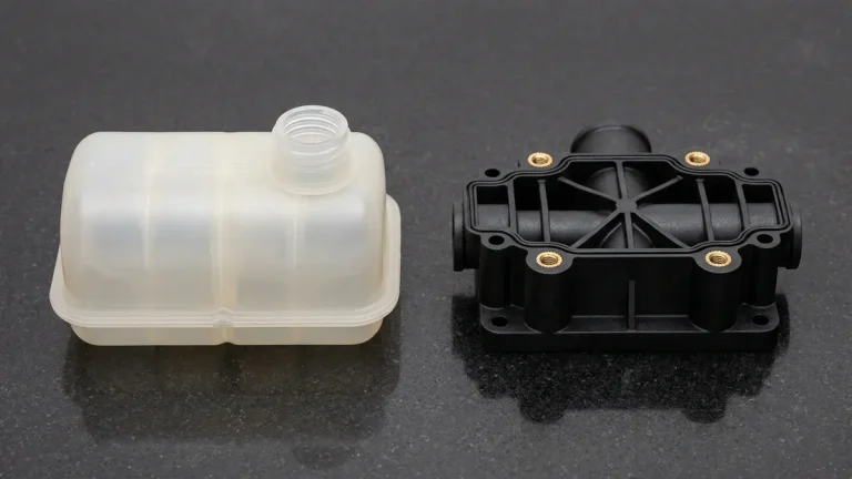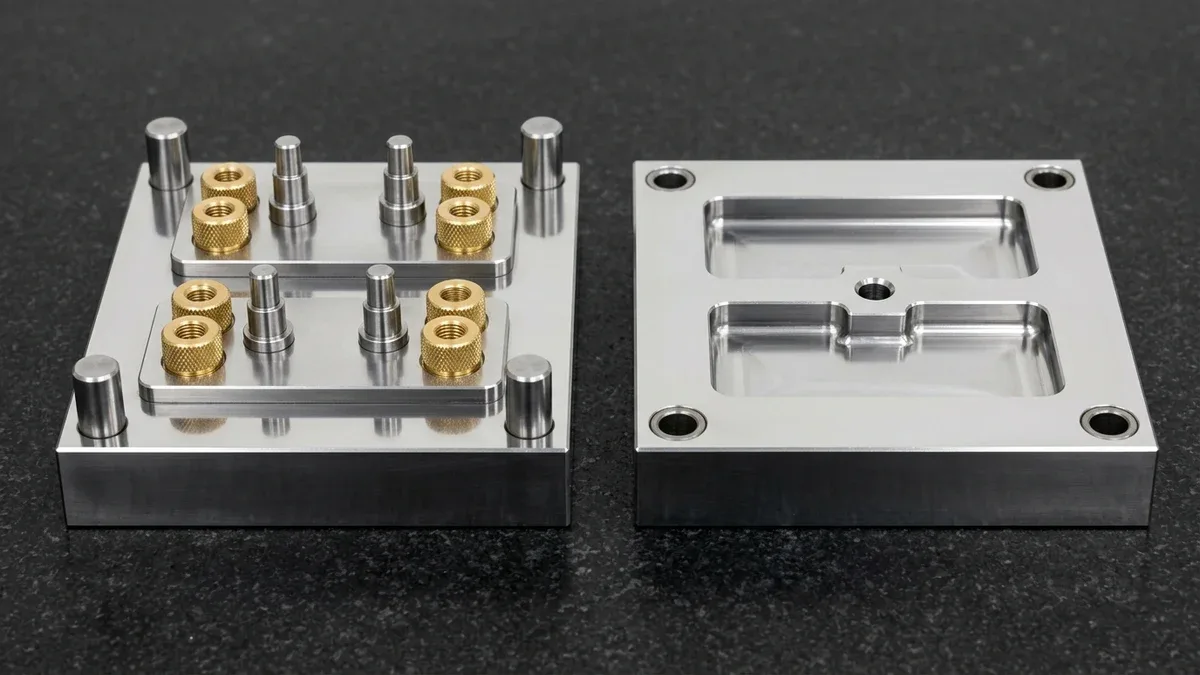
Modern engineering assemblies demand both structural lightweighting and durable mechanical fastening points. Therefore, understanding what is insert molding allows product teams to combine dissimilar materials into unified high-performance components. Insert molding is an advanced manufacturing technique where pre-manufactured components are placed directly into an injection mold cavity. Subsequently, molten thermoplastic resin encapsulates the insert, creating an inseparable mechanical bond upon cooling. In precision manufacturing, mastering insert molding process guide ensures repeatable dimensional stability and predictable production scaling.
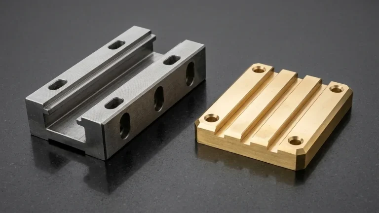
Typically, inserts consist of CNC machined brass threaded bushings, stainless steel dowel pins, or stamped copper electrical terminals. By molding resin directly around these metal inserts, engineers eliminate secondary fastening operations and adhesive bonding steps. Consequently, overall manufacturing cycle times decrease while assembly shear strength rises dramatically. In this technical guide, we evaluate core DFM principles, tooling setups, and material selection criteria for insert molding.
1. Tooling Kinematics: Vertical Clamping and Rotary Indexing Presses
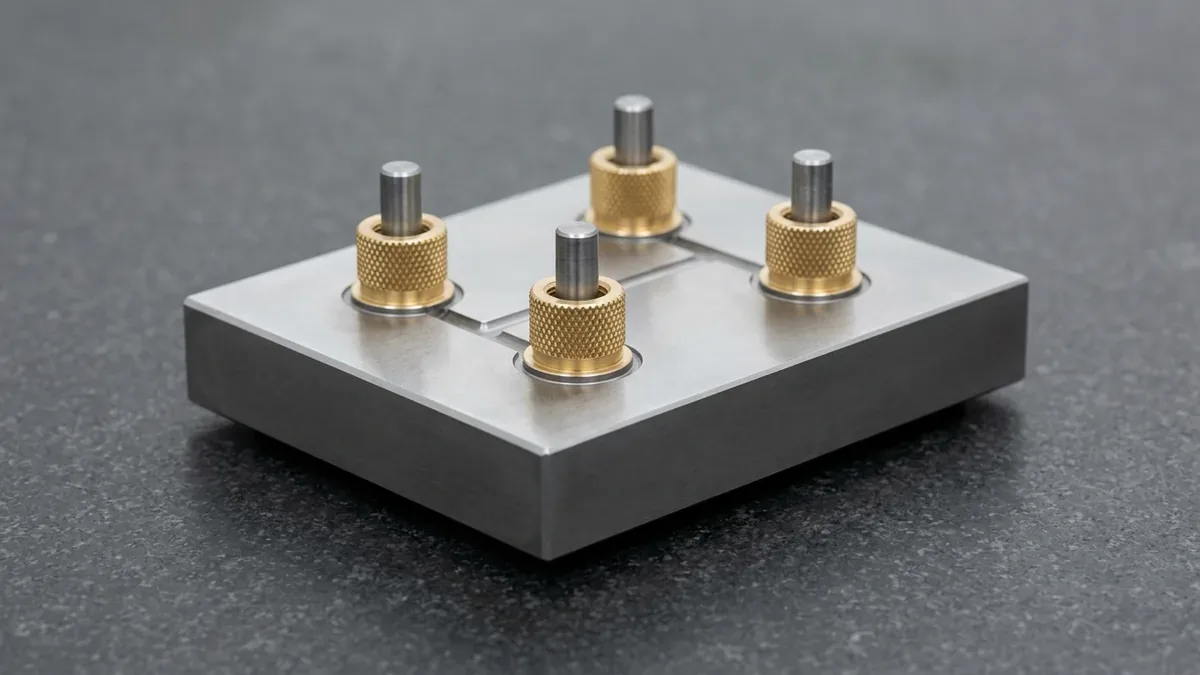
While standard injection molding often utilizes horizontal clamp presses, insert molding frequently employs vertical clamping machinery. Vertical clamp presses allow gravity to hold loose metal inserts securely onto tool core pins during mold closure. Consequently, operators or robotic end-effectors place inserts quickly without risking displacement or severe tool pinching.
Furthermore, high-volume production lines implement rotary shuttle tables containing two identical bottom mold halves. While one bottom tool undergoes high-pressure injection and cooling, the operator loads inserts into the opposite half. As a result, press utilization reaches near one hundred percent efficiency. Precision alignment pins ensure repeatable positioning within ±0.010 mm across every cycle.
2. Mechanical Retention and Resin Shrinkage Dynamics
Thermoplastics do not chemically adhere to bare metals during the molding process. Instead, insert retention relies entirely on mechanical interlocks and volumetric resin shrinkage. Engineers specify specialized outer surface textures on metal inserts, including diamond knurling, annular grooves, and undercuts. As molten resin cools, thermal contraction squeezes polymer tightly into these recessed micro-geometries.
However, excessive hoop stress can cause premature micro-cracking around insert bosses in brittle polymers like polycarbonate. Therefore, engineers maintain a boss wall thickness equal to at least the outer diameter of the insert. Through our custom injection molding services, tooling engineers optimize melt pathways. Consequently, this prevents cold weld lines forming near critical metal interfaces.
The comparative retention mechanics of various metal insert geometries are detailed in the engineering table below.
| Knurl Geometry Type | Primary Retention Mode | Torque Resistance | Axial Pullout Resistance |
|---|---|---|---|
| Diamond Knurling (Crossed) | Multi-directional mechanical lock | Exceptional | Very High |
| Straight Helical Knurling | Rotational shearing resistance | Outstanding | Moderate |
| Annular Undercut Grooves | Axial tensile barrier | Low | Maximum Tensile Strength |
| Hexagonal Stepped Body | Flat-face radial interference | Maximum Torque Strength | High |
| Smooth Barbed Surface | Interference frictional fit | Moderate | Moderate |
3. Prototyping Pathways and Production Scalability
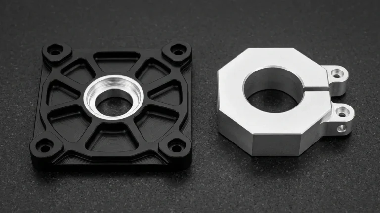
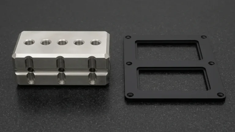
Developing insert-molded assemblies requires rigorous physical validation before cutting hardened production steel tooling. During initial prototyping, engineers frequently combine precision CNC machining with rapid tooling inserts. Machining custom brass inserts in-house ensures exact fitment before loading them into aluminum prototype molds.
Additionally, preheating metal inserts prior to mold placement significantly reduces residual molding stress. When room-temperature metal contacts hot plastic, rapid quenching freezes the surrounding resin immediately. Preheating inserts to approximately one hundred degrees Celsius prevents flash freezing, ensuring superior flow packing. In shop-floor practice, preheating dramatically improves tensile burst pressure around thick-walled electrical connector pins.
4. Insert Molding vs Two-Shot Overmolding
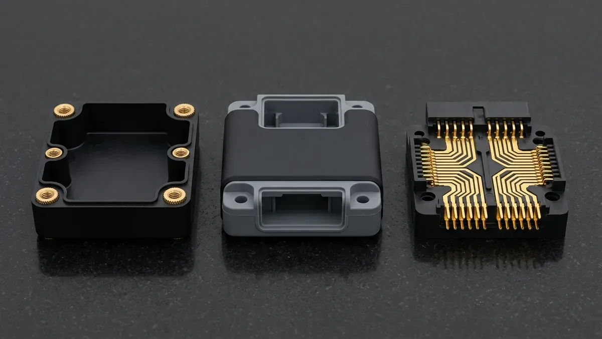
Product designers often evaluate whether insert molding or two-shot overmolding best serves their design requirements. Insert molding integrates discrete non-plastic elements, such as metals, ceramic insulators, or magnet cores. Conversely, two-shot overmolding injects a secondary soft thermoplastic elastomer over a rigid thermoplastic substrate. Consequently, the choice hinges primarily on whether electrical conductivity, high-load threads, or soft-touch ergonomics are required.
Moreover, insert molding delivers significantly lower tooling entry barriers for low-to-medium manufacturing volumes. While two-shot overmolding requires complex rotating platen tooling, insert molding runs reliably on single-barrel vertical presses. AS Prototypes offers comprehensive engineering support to optimize parting lines, pin shutoffs, and cycle automation.
The operational and architectural distinctions between these two processes are summarized in the table below.
| Feature Comparison | Precision Insert Molding | Two-Shot Overmolding |
|---|---|---|
| Substrate Material Class | Metals (brass, steel, copper), magnets, ceramic | Rigid engineering thermoplastics (PC, ABS, PA) |
| Overmolded Material | Thermoplastics (PA66, PBT, POM, PEEK) | Soft elastomers (TPE, TPU, Liquid Silicone) |
| Bonding Mechanism | Mechanical interlocking and thermal hoop shrinkage | Chemical melt adhesion and micro-mechanical grip |
| Tooling Complexity | Standard mold cavities with locator core pins | Dual-barrel rotating platen injection molds |
| Primary Application | Threaded structural fasteners, electrical busbars | Ergonomic tool grips, waterproof gasket seals |
5. Technical Engineering FAQ
Most commonly, inserts are metals such as brass, stainless steel, aluminum, and copper. However, ceramic rods, permanent magnets, and even cured silicone seals can also be encapsulated successfully.
Precision core pins feature tight shut-off diameters matching the insert bore. When the mold closes, the core pin creates a rigid mechanical seal. This tight shutoff prevents molten resin ingress into internal threads.
Preheating inserts prevents rapid localized cooling of the polymer melt front. This minimizes internal molded-in stresses, prevents sink marks, and ensures uniform crystallization around the metal insert.
Transition Seamlessly from Rapid Tooling to High-Precision Molding
Optimize cavity life, gate geometry, and part unit economics with our in-house tooling and injection molding engineering team. Upload your 3D CAD models (STEP/IGES) for a comprehensive Moldflow and DFM manufacturability assessment.
Upload 3D CAD for Tooling & Molding DFM Review