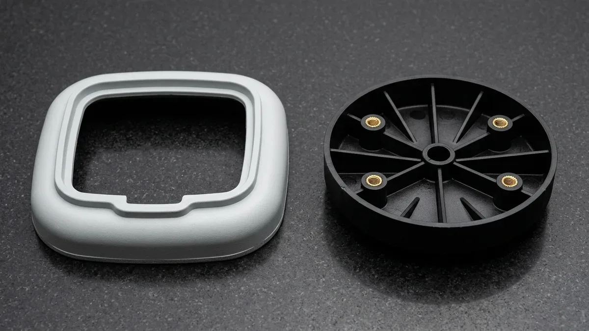
Thermoforming vs Injection Molding represents a fundamental Design for Manufacturability (DFM) trade-off between single-sided heated sheet stretching and high-pressure closed-cavity melt injection. While heavy-gauge thermoforming reduces initial Non-Recurring Engineering (NRE) tooling investment to 0.15x–0.30x of an injection mold baseline, it introduces severe draw-ratio wall thinning and secondary Computer Numerical Control (CNC) trimming overhead.
From a continuum mechanics standpoint, heating an extruded polymer sheet and stretching it across a single-sided male or female mold conserves solid volume while expanding surface area. Consequently, deep corners thin down by 45% to 75%, and the free non-contact surface cannot form integral stiffening ribs, cored screw bosses, or precision snap-fit undercuts.
In our in-house mold shop and injection molding department, we help engineering teams navigate this process boundary across prototype and production stages. By combining rapid aluminum and steel custom plastic injection molding and bridge tooling with polyurethane vacuum casting, we hold closed-cavity tolerances down to ±0.05 mm (±0.002″) under ISO 20457 (DIN 16742).
Executive Summary & Engineering Takeaways (BLUF)
- Tooling NRE vs. Unit Cost Crossover: Single-sided 6061-T6 aluminum thermoforming molds require 0.15x–0.30x Tooling NRE compared to a 1.0x Rapid Injection Mold Baseline (and 2.2x–3.8x for hardened H13/S136 multi-cavity production steel molds), but sheet trim scrap and 5-axis CNC routing raise thermoformed unit costs to 3.0x–6.0x, placing the break-even crossover at 350 to 500 units for mid-sized housings.
- Draw-Ratio Wall Thinning Physics: Stretching an initial t0 = 4.00 mm (0.157″) extruded ABS sheet over a 400 × 300 × 120 mm enclosure (areal draw ratio Ra = 2.40) reduces average wall thickness to 1.67 mm (0.066″) and thins deep bottom corners to 0.92 mm (0.036″), whereas closed-cavity injection molding maintains a uniform 2.00 mm (0.079″) wall with 1.00 mm internal ribs.
- Dimensional Tolerances & Draft Angles: Precision injection molding holds ISO 20457 (DIN 16742) general tolerances of ±0.05 to ±0.15 mm (±0.002″ to ±0.006″) and critical features to ±0.025 mm (±0.001″) with 0.5°–1.0° base draft; vacuum and pressure thermoforming hold ±0.25 to ±1.50 mm (±0.010″ to ±0.060″) and require 3.0°–5.0° draft on male plugs.
- Thermoplastic Resin Compatibility: Thermoforming is restricted to amorphous or high-melt-strength extruded sheets (ABS, PMMA, PC, PETG, HDPE) that exhibit a stable rubbery plateau; sharp-melting semi-crystalline engineering polymers (PA66-GF30, POM-C, PBT, PEEK) require closed-cavity injection molding.
- Ex-Factory Turnaround Benchmarks: Our in-house facilities deliver RTV silicone vacuum cast prototypes in 7 to 12 business days, rapid aluminum/soft-steel bridge injection tooling with T1 samples in 12 to 18 business days, and hardened steel production tooling in 18 to 35 business days (Ex-Factory Production & Inspection Turnaround, separate from 3 to 5 business days air transit).
Article Engineering Navigation
- 1. Process Physics Compared: Single-Sided Sheet Stretching (Vacuum & Pressure Forming) vs. 3D Closed-Cavity Melt Injection
- 2. Why Does Thermoforming Suffer from Draw-Ratio Wall Thinning While Injection Molding Controls 3D Ribs & Bosses?
- 3. Dimensional Tolerances (ISO 20457 vs. Trim-Routed Edges), Draft Angles & Secondary 5-Axis CNC Trimming Requirements
- 4. Thermoplastic Material Selection Matrix: Extruded Sheet Grades (ABS, PC, PMMA, HDPE, PETG) vs. Engineering Molding Resins (PA66-GF30, POM-C, PEEK, PBT)
- 5. Shop-Floor Failure Troubleshooting (Webbing, Corner Thinning & Boss Delamination vs. Weld Lines) & Metrology Verification
- 6. The Engineering Verdict: When to Choose Thermoforming, Polyurethane Vacuum Casting, or Injection Molding
- 7. Technical Engineering FAQ
To establish a quantitative engineering baseline before examining draw-ratio math and mold metallurgy, the executive comparison matrix below contrasts heavy-gauge vacuum forming, pressure thermoforming, rapid bridge injection molding, and multi-cavity production injection molding across key manufacturing metrics.
| Engineering Parameter | Heavy-Gauge Vacuum Thermoforming | Pressure Thermoforming (Positive Air + Vacuum) | Rapid Bridge Injection Molding (7075-T6 / P20) | Production Injection Molding (H13 / S136 Steel) |
|---|---|---|---|---|
| Forming Physics & Pressure | Single-sided sheet stretching via vacuum differential (0.08–0.098 MPa / 12–14.2 psi) | Single-sided mold with top positive air pressure + vacuum (0.28–0.69 MPa / 40–100 psi) | Closed 3D core & cavity shear melt injection (50–110 MPa / 7,250–15,950 psi cavity pressure) | High-pressure closed 3D multi-cavity injection (70–150 MPa / 10,150–21,750 psi) |
| Tooling Metallurgy & Hardness | Cast or CNC-milled 6061-T6 aluminum (~95 HB) or high-temp syntactic epoxy board | Temperature-regulated billet 6061-T6 / 7075-T6 aluminum with micro-vent holes | 7075-T651 aluminum (~150 HB) or pre-hardened P20 / 718H (28–34 HRC) & NAK80 (37–42 HRC) | Through-hardened H13 or S136 / AISI 420SS tool steel (48–52 HRC) |
| Relative Tooling NRE Ratio | 0.15x – 0.25x (Lowest Single-Sided NRE) | 0.25x – 0.45x (Includes pressure bell & plug assist) | 1.0x Baseline (Single-cavity rapid bridge mold) | 2.2x – 3.8x Baseline (Hardened multi-cavity / hot-runner steel mold) |
| Relative Unit Cost Ratio | 3.0x – 5.0x (Sheet extrusion premium + 5-axis CNC trim time) | 3.5x – 6.0x (Longer heating/cooling cycle + precision CNC routing) | 1.0x Baseline (30–60 s automated net-shape molding cycle) | 0.55x – 0.80x Baseline (Multi-cavity high-speed automation) |
| Achievable Tolerances (mm / in.) | Molded: ±0.50–1.50 mm (±0.020″–0.060″); CNC trimmed edge: ±0.25–0.38 mm | Molded: ±0.25–0.50 mm (±0.010″–0.020″); CNC trimmed edge: ±0.25 mm (±0.010″) | ISO 20457 general: ±0.05–0.15 mm (±0.002″–0.006″); critical features: ±0.025 mm | ISO 20457 tight class: ±0.025–0.080 mm (±0.001″–0.003″) |
| Wall Thickness & 3D Ribs/Bosses | Non-uniform (thins 45%–75% in deep corners); zero integral internal ribs or bosses | Crisp outer texture & radii, but inner wall remains uncontrolled; bosses must be bonded | 100% controlled 3D walls (0.8–4.0 mm) with integral 0.5t–0.6t ribs, bosses & snap hooks | 100% uniform 3D geometry, overmolding, brass inserts & complex side-action undercuts |
| Recommended Application / When to Choose | Best for large simple covers, protective trays, and shrouds (>600 mm) at 50–1,500 pcs/year | Best for large cosmetic medical cart housings & kiosks (500–1,200 mm) at 100–2,500 pcs/year | Best for functional DVT/PVT housings & technical parts (<600 mm) from 350 to 10,000+ pcs | Best for high-volume precision assemblies (10,000 to 1,000,000+ pcs) requiring tight Geometric Dimensioning and Tolerancing (GD&T) |
1. Process Physics Compared: Single-Sided Sheet Stretching (Vacuum & Pressure Forming) vs. 3D Closed-Cavity Melt Injection
Thermoforming heats a pre-extruded thermoplastic sheet into its rubbery thermoelastic plateau (140°C–210°C / 284°F–410°F) and stretches it over a single-sided mold using 0.08–0.69 MPa (12–100 psi) pneumatic pressure. Conversely, injection molding melts resin pellets (200°C–390°C) and injects liquid polymer into a closed steel cavity at 50–150 MPa (7,250–21,750 psi).
While single-sided forming avoids high-tonnage clamping presses, low pneumatic differentials cannot force solid polymer chains to flow laterally into freestanding internal ribs or screw bosses. Understanding how pressure regimes dictate mold architecture is essential before committing capital to production tooling.
In heavy-gauge vacuum forming (starting sheet thickness t0 = 1.5 mm to 12.0 mm / 0.060″ to 0.472″), ceramic or quartz infrared heater banks warm the clamped sheet until it sags. Opening vacuum valves evacuates trapped air through Ø0.5–0.8 mm (0.020″–0.031″) micro-holes, applying at most 0.098 MPa (14.2 psi) atmospheric differential.
Because a 0.098 MPa vacuum differential cannot overcome the biaxial extensional viscosity of thick sheets around tight radii, vacuum-formed parts exhibit generous outer corner radii (Rmin ≥ 3t to 5t) and muted surface grain. It remains restricted to utility covers, material handling trays, and simple equipment guards.
Pressure thermoforming narrows the cosmetic gap on the mold-contact surface by sealing a positive-pressure bell housing above the heated sheet. Simultaneously pulling a bottom vacuum while injecting 0.28 to 0.69 MPa (40 to 100 psi) of compressed air multiplies the forming force by four to seven times.
Under 0.55 MPa (80 psi) positive air pressure, the softened sheet conforms tightly against textured 6061-T6 aluminum cavity walls, reproducing fine grain patterns (equivalent to VDI 24–30) and crisp exterior radii down to 1.5t. However, the interior side facing the air pressure bell remains an unconstrained free boundary.
Even in twin-sheet thermoforming—where two heated sheets are vacuum-formed simultaneously and fused along pinch-off zones to create hollow double-walled pallets or ducts—each individual skin still stretches uniaxially and thins at deep corners. Moreover, twin-sheet fusion seams require heavy perimeter router trimming and cannot form precision internal printed circuit board (PCB) standoffs.
By contrast, closed-cavity injection molding operates via viscous shear flow inside a precision-machined two-plate or three-plate metal mold mounted in our electric Fanuc or hydraulic Haitian presses (50 to 650 metric tons clamping force). The reciprocating screw plasticizes pellets and packs the cavity between rigid core and cavity blocks.
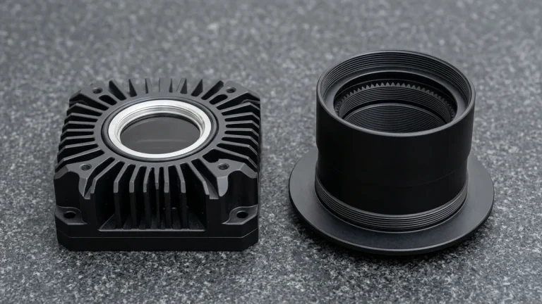
Because packing pressure reaches 70 to 140 MPa inside an enclosed steel volume, both exterior cosmetic walls and interior structural cores are mechanically constrained. As shown on our granite plate below, a single-sided 6061-T6 aluminum plug with vacuum micro-holes differs fundamentally from a ground steel cavity insert with submarine gates.
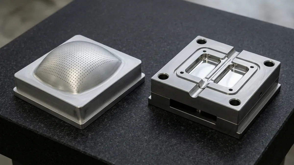
- Single-Sided 6061-T6 Aluminum Thermoforming Molds: Experiencing less than 0.7 MPa surface pressure and zero high-velocity melt abrasion, thermoforming tools are CNC-milled from single-sided 6061-T6 aluminum blocks with drilled vacuum evacuation passages, requiring only 0.15x to 0.30x of our baseline injection mold NRE.
- Rapid Bridge Injection Tooling (7075-T651 / Pre-Hardened P20 & NAK80): To withstand 60–110 MPa injection packing pressure and clamp tonnage across 500 to 50,000 shots, rapid bridge molds pair precision-milled 7075-T651 aluminum or pre-hardened P20 / 718H (28–34 HRC) and NAK80 (37–42 HRC) core-and-cavity blocks with ejector pin plates and cooling lines (1.0x Baseline NRE).
- High-Volume Production Steel Tooling (Through-Hardened H13 / S136): Multi-cavity molds running abrasive glass-filled resins over 100,000 to 1,000,000+ cycles utilize vacuum heat-treated H13 or S136 (AISI 420SS) tool steel at 48–52 HRC with hardened sliding shut-offs (2.2x to 3.8x Baseline NRE).
2. Why Does Thermoforming Suffer from Draw-Ratio Wall Thinning While Injection Molding Controls 3D Ribs & Bosses?
Thermoforming thins plastic walls because a clamped sheet of fixed volume stretches biaxially over a larger 3D mold area, reducing average thickness inversely with the areal draw ratio (tavg = t0 ÷ Ra), whereas closed-cavity injection molding maintains uniform 3D walls, ribs, and bosses.
When a heated polymer sheet contacts a cold or warm aluminum mold surface, friction and rapid conductive cooling immediately freeze the polymer skin at the contact zone. As vacuum or positive air pressure continues drawing the remaining suspended web into deep pockets or over tall male corners, all subsequent elongation concentrates in the uncooled corners.
Consequently, even when the linear depth-to-width draw ratio (H ÷ W) is a modest 0.40:1 to 0.60:1, local wall thickness at the last-forming bottom radius typically drops to 45%–60% of the average stretched wall—or only 20%–35% of the initial sheet gauge (t0).
To mitigate extreme corner thinning on female molds, thermoformers deploy heated syntactic-foam mechanical plug assists and pneumatic pre-billow bubble stretching to pre-distribute sheet gauge before vacuum evacuation. Even so, preventing corner blowouts still forces engineers to specify an oversized starting sheet (4.0 mm to 6.0 mm), which penalizes part weight and sheet cost.
Furthermore, because single-sided thermoforming cannot form internal stiffening ribs, resisting panel flexing requires thick solid walls. Because flexural rigidity scales with the cube of section height (D ∝ E × t3), injection molding replaces heavy solid skins with a thin 2.0 mm (0.079″) outer shell reinforced by an internal grid of 1.0–1.2 mm vertical ribs.
Keeping internal rib thickness at 0.50t to 0.60t of the nominal wall multiplies flexural stiffness by 3.5x to 5.0x without cosmetic sink marks, as detailed in our plastic injection molding wall thickness guide.
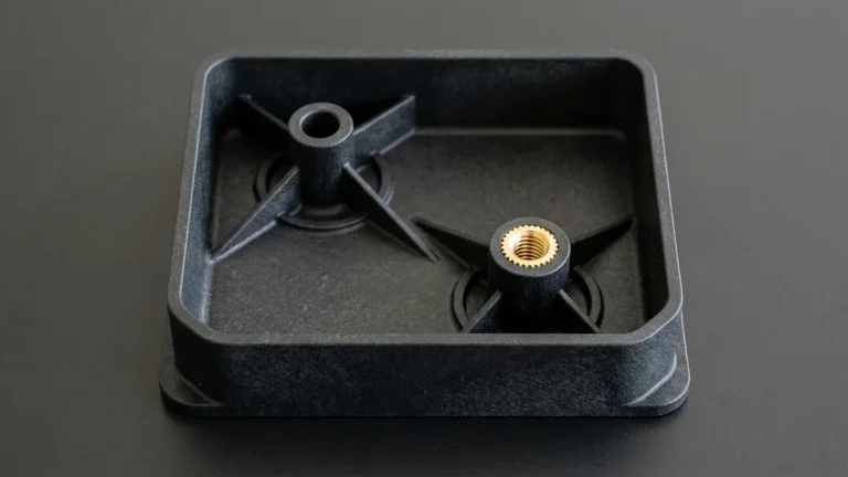
Closed injection molds also form integral B-side screw bosses using a strict 0.50t–0.60t boss-to-wall ratio and 0.25t–0.50t base fillets, whose sizing equations are covered in our injection molding screw boss design DFM guide.
Where enclosures require fastenerless assembly, closed molds form tapered cantilever snap hooks (1.5%–4.0% permissible root strain) via pass-through shut-offs or lifters, as derived in our cantilever snap-fit strain and mold shut-off DFM guide.
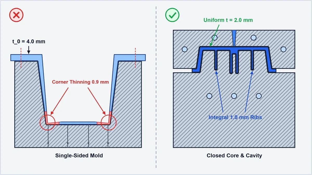
Compare these two cross-sectional profiles in the 2D Computer-Aided Design (CAD) engineering schematic below: single-sided thermoforming stretches a t0 = 4.0 mm sheet into 0.9 mm thinned corners without internal features, whereas closed-cavity molding holds a uniform t = 2.0 mm wall with 1.0 mm integral ribs.
📐 4-Step Quantitative Derivation: Thermoforming Draw-Ratio Thinning & Normalized Break-Even Volume
- Step 1 — Enclosure Geometry & Process Inputs: Consider a rectangular medical cart instrument shroud with projected opening length
L = 400 mm (15.75″), widthW = 300 mm (11.81″), and vertical draw depthH = 120 mm (4.72″). Route A uses female pressure thermoforming starting from an extrudedABSsheet of thicknesst0 = 4.00 mm (0.157″)(tooling indexINRE,TF = 220 CU, piece cost index including sheet scrap & 5-axis CNC routingiunit,TF = 3.20 CU). Route B uses rapid bridge injection molding with uniformt = 2.00 mm (0.079″)walls and1.00 mmribs (tooling indexINRE,IM = 1,000 CU, net-shape piece cost indexiunit,IM = 1.00 CU). - Step 2 — Continuum Conservation & Economic Crossover Equations:
Projected footprint area:A0 = L × W| Stretched 5-face shell area:Aformed = (L × W) + 2(L + W) × H
Areal draw ratio:Ra = Aformed ÷ A0| Mean stretched wall thickness:tavg = t0 ÷ Ra| Deep bottom corner thickness (empirical unassisted draw factorkc ≈ 0.55):tcorner = kc × tavg
Normalized break-even production volume:Ncross = (INRE,IM − INRE,TF) ÷ (iunit,TF − iunit,IM) - Step 3 — Step-by-Step Numerical Calculation:
1. Footprint & formed surface area:A0 = 400 × 300 = 120,000 mm²;Aformed = 120,000 + 2(400 + 300) × 120 = 120,000 + 168,000 = 288,000 mm².
2. Areal draw ratio & mean wall:Ra = 288,000 ÷ 120,000 = 2.40;tavg = 4.00 mm ÷ 2.40 = 1.67 mm (0.066″).
3. Deep corner wall thickness:tcorner = 0.55 × 1.67 mm = 0.92 mm (0.036″)— a 77.0% thickness loss from the 4.00 mm starting sheet, dropping below the 1.25 mm impact threshold!
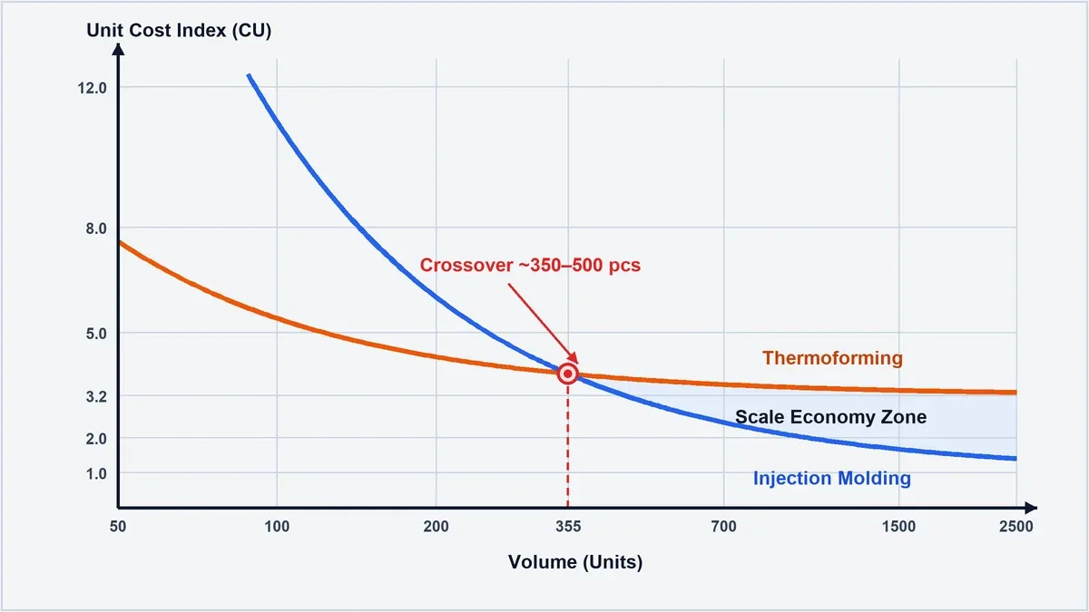
4. Break-even volume crossover:Ncross = (1,000 CU − 220 CU) ÷ (3.20 CU − 1.00 CU) = 780 ÷ 2.20 = 354.5 ≈ 355 units.
Step 4 — Shop-Floor Engineering Verdict: Keeping the thermoformed corner above 1.50 mm requires a heated syntactic-foam plug assist or raising starting gauge to t0 = 6.0 mm (raising iunit,TF to 4.10 CU and lowering Ncross to 252 units). Above 350 to 500 units, rapid injection molding delivers lower total cost with uniform 2.00 mm walls and integral bosses.
3. Dimensional Tolerances (ISO 20457 vs. Trim-Routed Edges), Draft Angles & Secondary 5-Axis CNC Trimming Requirements
Closed-cavity injection molding holds tight linear tolerances of ±0.05 to ±0.15 mm (±0.002″ to ±0.006″) under ISO 20457 (DIN 16742) because solidification occurs under 60–120 MPa packing pressure inside ground steel cavities. Conversely, thermoformed shells cool against a single-sided aluminum surface and require CNC routing, yielding tolerances of ±0.25 to ±1.50 mm.
In injection molding, thermal shrinkage (such as 0.4% to 0.7% for amorphous ABS or PC/ABS) is compensated directly in the steel cavity CAD scaling factor. Because closed steel constrains both inner and outer walls until ejection, bore-to-bore true position and perimeter step rebates repeat within ±0.025 to ±0.050 mm (±0.001″ to ±0.002″).
In thermoforming, dimensional stack-up stems from three uncoupled variables: extruded sheet thickness tolerance (typically ±5% to ±10% from the sheet mill), differential thermal shrinkage on the unmolded air-cooled face, and post-mold fixture clamping error during secondary CNC trimming.
Every thermoformed shell exits the forming station attached to a perimeter clamping frame web that must be sheared away. For 3D housings requiring side connector cutouts, louver slots, and stepped mounting flanges, each shell must be mounted onto a vacuum routing fixture and trimmed on a 5-axis CNC router using high-helix solid carbide compression cutters.
Even with rigid vacuum holding fixtures, thin formed plastic shells flex elastically under routing cutter forces, limiting trimmed edge-to-feature positional accuracy to ±0.25 to ±0.38 mm (±0.010″ to ±0.015″). Moreover, the clamped perimeter web and window cutouts generate 25% to 45% raw sheet skeleton scrap that elevates unit material cost.
- Male vs. Female Thermoforming Draft Angles: As a heated thermoplastic sheet cools on a male plug tool, thermal contraction causes the plastic to shrink tightly inward onto the metal core, requiring a generous 3.0° to 5.0° draft angle for release without scuffing. On a female cavity tool, the sheet shrinks inward away from the cavity walls, allowing tighter 1.0° to 2.0° draft angles (though exterior corners become softer than on a male plug).
- Injection Molding Draft & VDI 3400 Texture Rules: Closed injection molds incorporate precision ejector pin arrays and stripper plates, allowing smooth polished walls to release cleanly at 0.5° to 1.0° draft (1.5° to 3.0° on deep internal ribs). For spark-eroded or chemically etched cosmetic surfaces, apply our shop-floor rule: add 1.0° to 1.5° of additional draft per 0.025 mm (0.001″) of texture depth—meaning VDI 24 (Ra 1.6 µm) requires 1.5°–2.0° and VDI 30 (Ra 3.2 µm) requires 2.5°–3.0° to prevent drag marks.
- Controlled Inner vs. Outer Mating Surfaces: A single-sided thermoforming mold controls only the tool-contact surface: a female mold controls the outer cosmetic profile (leaving the inside wall thickness variable by ±15%), whereas a male mold controls the inner mounting contour (leaving the outer dimensions dependent on local sheet thinning). Injection molding simultaneously controls both inner and outer datum surfaces to ISO 20457 precision.
4. Thermoplastic Material Selection Matrix: Extruded Sheet Grades (ABS, PC, PMMA, HDPE, PETG) vs. Engineering Molding Resins (PA66-GF30, POM-C, PEEK, PBT)
Thermoplastic material selection divides sharply between thermoforming and injection molding because single-sided sheet forming requires amorphous or branched polymers with high melt strength across a wide rubbery thermoelastic window, whereas closed-cavity injection molding processes both amorphous blends and sharp-melting, fiber-reinforced semi-crystalline engineering resins.
During thermoforming, the clamped plastic sheet is suspended horizontally over an open heater bed and supported solely by its hot extensional viscosity. Amorphous sheets—including ABS, Polycarbonate (PC), PMMA (Acrylic), PETG, and PVC—gradually soften above their glass transition temperature (Tg = 80°C–150°C) without undergoing a sudden solid-to-liquid collapse.
However, extruded sheets retain calendering machine-direction molecular orientation from the sheet mill. When reheated in a thermoforming oven, this frozen uniaxial orientation causes asymmetric sheet sag and differential shrinkage between the extrusion and transverse directions, whereas injection molding controls shrinkage isotropically via uniform gate packing.
Conversely, linear semi-crystalline engineering polymers—including POM-C (Acetal), PA66 (Nylon), PBT, and PEEK—possess a sharp crystalline melting point (Tm). Once heated to Tm, their viscosity plummets abruptly into a water-thin fluid that sags or tears in an open sheet clamp frame, restricting them to closed-cavity injection molding.
Furthermore, in our in-house injection molding department, adding 15% to 30% short glass or carbon fiber reinforcement (such as PA66-GF30 or PC-GF20) raises flexural modulus to 5,500–10,500 MPa (798–1,523 ksi) and cuts linear shrinkage to 0.2%–0.5%. In thermoforming, heavy fiber loadings restrict sheet elongation and expose rough surface fibers.
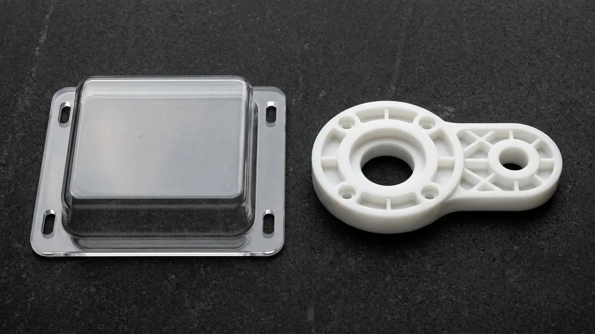
As demonstrated on our granite inspection plate below, transparent amorphous polycarbonate sheets excel in thermoformed machine guards with CNC-routed mounting slots, whereas high-crystallinity acetal (POM-C) bearing linkages with cored lattice pockets require closed-cavity injection molding.
When to Avoid Thermoforming — Critical Material and Structural Limitations Where Single-Sided Sheet Forming Fails in Service:
- Avoid High-Crystallinity Low-Friction Wear Parts (POM-C, PA66, PBT, PEEK): Crystalline resins exhibit extreme sheet sag and 1.5%–2.5% volumetric crystallization shrinkage during open-air cooling; always specify closed-cavity injection molding or CNC billet plastic machining for gears, bearing carriers, and autoclave-sterilizable PEEK components.
- Avoid Elastomer-Sealed Waterproof Enclosures (IP67 / IP68): Compressing a perimeter silicone O-ring to a uniform 15%–25% squeeze ratio (AS568) requires a flat gland groove within ±0.05 mm and closely spaced screw bosses that single-sided sheet forming cannot hold.
- Avoid Un-Annealed PMMA / PC Exposed to Solvents: Biaxial sheet stretching locks high frozen-in tensile orientation stress into clear PMMA and PC shields; wiping un-annealed thermoformed windows with isopropyl alcohol or strong hospital disinfectants triggers immediate environmental stress cracking (crazing).
| Thermoplastic Grade | Process Compatibility | Flexural Modulus E (MPa / ksi) | Forming / Melt Window (°C) | Linear Shrinkage (%) | Recommended Application / When to Choose |
|---|---|---|---|---|---|
| ABS / Flame-Retardant ABS-PVC | Both (Workhorse for Sheet & Pellet) | 1,900–2,400 MPa (276–348 ksi) | Sheet: 145–180°C | Melt: 210–250°C | 0.4% – 0.7% | Best for textured medical cart shrouds (pressure formed) and ribbed electronic housings (injection) |
| PC & PC/ABS Alloy Blend | Both (Requires Pre-Drying at 120°C) | 2,200–2,500 MPa (319–363 ksi) | Sheet: 175–210°C | Melt: 260–305°C | 0.5% – 0.7% | Best for high-impact transparent machine guards (sheet) and precision diagnostic bezels (injection) |
| PMMA (Acrylic) & PETG | Both (PETG excels in deep-draw sheet) | 2,100–3,100 MPa (305–450 ksi) | Sheet: 135–175°C | Melt: 220–260°C | 0.3% – 0.6% | Best for UV-stable skylights & sterile medical packaging trays (sheet) or optical lenses (injection) |
| HDPE (High-Molecular-Weight) | Heavy-Gauge Vacuum & Injection | 900–1,350 MPa (131–196 ksi) | Sheet: 150–185°C | Melt: 200–250°C | 1.5% – 3.0% | Best for chemical-resistant dunnage pallets and agricultural vehicle fenders where ±1.5 mm is acceptable |
| POM-C (Acetal Copolymer) | Injection Molding Only (Not Thermoformed) | 2,600–2,900 MPa (377–421 ksi) | Melt: 190–215°C (Mold: 80–105°C) | 1.8% – 2.2% | Best for low-friction gears, twin-bore linkage arms, and high-cycle fatigue snap latches |
| PA66-GF30 & PBT-GF30 | Injection Molding Only (Not Thermoformed) | 8,000–10,500 MPa (1,160–1,523 ksi) | Melt: 265–295°C (Mold: 80–110°C) | 0.2% – 0.6% | Best for high-load structural brackets, robotics motor mounts, and automotive connector housings |
| PEEK & PEI (Ultem 1000) | Injection Molding (PEI limited aircraft sheet) | 3,300–4,100 MPa (479–595 ksi) | Melt: 350–400°C (Mold: 160–200°C) | 0.7% – 1.3% | Best for 200°C+ aerospace structural isolators, semiconductor wafer carriers, and medical manifolds |
5. Shop-Floor Failure Troubleshooting (Webbing, Corner Thinning & Boss Delamination vs. Weld Lines) & Metrology Verification
Preventing field structural failures requires diagnosing process-specific defects before releasing tooling for production. In thermoforming, failure modes center on corner draw-down tearing, male-mold webbing folds, and adhesive boss delamination; in injection molding, defects center on weld lines (knit lines) around multi-window cutouts, sink marks, and air-trap burns.
Below are three representative shop-floor troubleshooting cases following our strict Symptom → Root Cause → Corrective Action engineering workflow:
- Deep-Draw Corner Translucent Thinning & Webbing Folds (Thermoforming):
Symptom: A 150 mm deep ABS housing formed over a male plug exhibits folded diagonal creases (webbing) at the base flange and paper-thin 0.75 mm corners that crack during drop testing.
Root Cause: Excessive linear draw ratio (H ÷ W = 0.65:1) combined with oversized sheet sag caused the excess curtain of hot plastic to fold against itself before vacuum evacuation finished, while early freeze-off on the plug top starved the bottom corners.
Corrective Action: Switch to a female cavity mold paired with a heated syntactic-foam mechanical plug assist (sized to 80%–85% of cavity geometry and held at 115°C–125°C) plus pre-billow pneumatic bubble stretching to distribute wall thickness above 1.65 mm. - Secondary-Bonded Mounting Standoff Pull-Out Under Vibration (Thermoforming):
Symptom: Machined ABS mounting blocks glued to the inside of a pressure-formed cart bezel delaminate under 4.5 N·m fastener torque and shipping vibration.
Root Cause: The free inside surface of a female-formed sheet experiences variable wall thickness and localized residual shrinkage stress, leaving an uneven gap (>0.4 mm) that starves cyanoacrylate or rigid epoxy bonds.
Corrective Action: Where production volume exceeds 350 units, convert the bezel to rapid injection molding with integral cored bosses and flush-molded knurled brass inserts (retaining ≥1.8 mm surrounding boss wall thickness). For low-volume shells, use two-part methacrylate structural adhesive with 0.25 mm glass-bead bond-line spacers. - Knit-Line Fracture & Sink Marks on Multi-Window Bezels (Injection Molding):
Symptom: An injection-molded matte black PC/ABS dual-window instrument bezel shows a visible cosmetic weld line across the central bridge bar and slight surface sink opposite internal mounting ribs.
Root Cause: Split melt fronts flowing around the two rectangular window shut-offs converged below 240°C without sufficient venting, while internal ribs were designed at 0.80t (1.6 mm on a 2.0 mm wall).
Corrective Action: In our in-house mold shop, we relocate submarine gates via Moldflow simulation to shift the knit line into a non-structural flange, machine 0.015–0.025 mm (0.0006″–0.001″) perimeter vent channels with an overflow well at the weld zone, and thin internal ribs to 0.50t (1.0 mm).
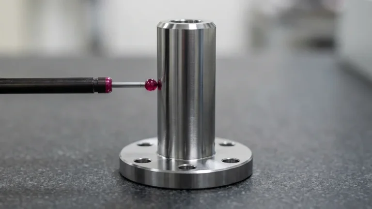
In our 20°C ± 1°C temperature-controlled metrology laboratory, we match inspection instrumentation strictly to part rigidity. Because thin-walled thermoformed shells and unmounted polymer bezels flex under mechanical contact forces, we never probe compliant plastic walls with a heavy contact stylus.
Instead, as shown in the optical inspection setup below, we verify thin-wall injection-molded bezels and precision polymer housings to ±0.010 mm (±0.0004″) using non-contact 2.5D Optical Vision Measuring Systems (VMS) with telecentric green backlighting, complemented by dedicated CNC-machined checking fixtures, calibrated cylindrical steel pin gauges, and feeler gauges for mating fit-up.
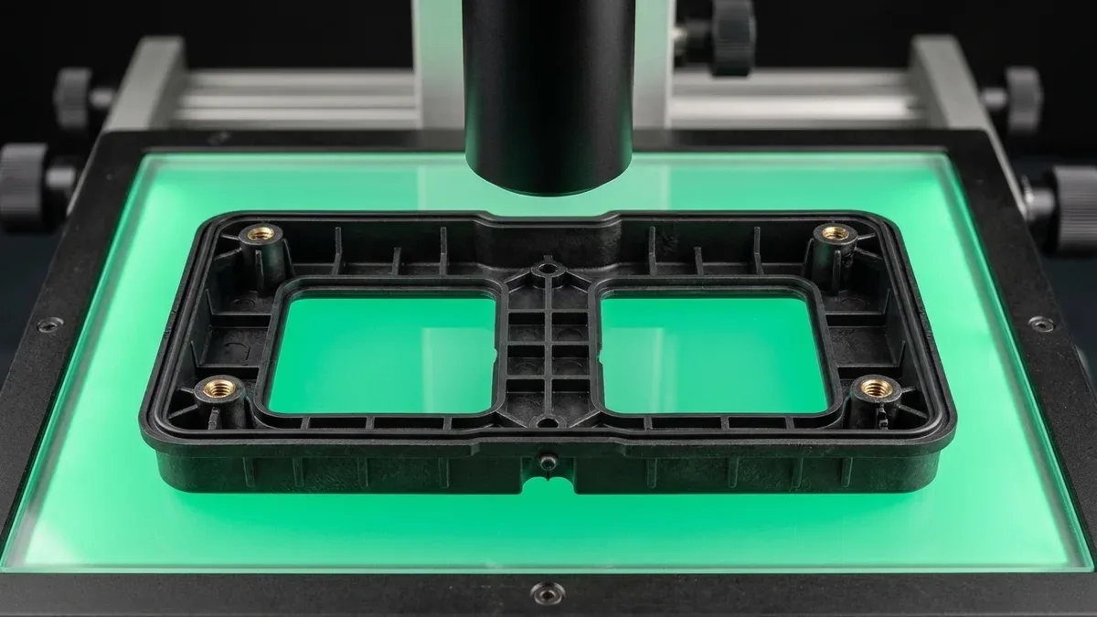
For rigid mold cores and glass-filled datum housings, our Zeiss bridge Coordinate Measuring Machines (CMMs) execute First Article Inspection (FAI) to ±0.002 mm repeatability, as detailed in our CMM precision metrology and GD&T verification guide.
6. The Engineering Verdict: When to Choose Thermoforming, Polyurethane Vacuum Casting, or Injection Molding
Selecting the optimal polymer manufacturing route depends on four quantitative engineering boundaries: projected part envelope, annual production volume relative to the 350–500 unit NRE crossover, internal 3D feature complexity (ribs, bosses, and snap-fits), and required dimensional tolerance class.
Examine the normalized unit cost trajectory in the engineering schematic below, which plots total amortized cost per part (in Normalized Cost Units, CU) across production volume for single-sided thermoforming versus closed-cavity rapid injection molding to pinpoint the 355-unit break-even crossover.
Before defaulting to thermoforming for small-batch housings or committing to high-tonnage steel molds for oversized panels, hardware teams should also evaluate three orthogonal polymer molding alternatives in our technology portfolio:
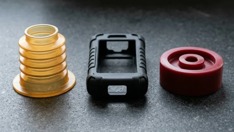
- 10 to 50 Units With Full 3D Ribs & Zero Wall Thinning (Polyurethane Vacuum Casting): Rather than accepting single-sided thermoforming wall thinning during EVT/DVT builds of 10 to 50 enclosures, cast two-part polyurethane resins inside Room-Temperature Vulcanizing (RTV) silicone molds (15–25 shots/mold, ±0.15–0.30 mm tolerances) via our custom polyurethane vacuum casting services; see our polyurethane vacuum casting and silicone mold life guide for resin selection.
- 50 to 1,000 Large Structural Medical Housings With Integral Bosses (Reaction Injection Molding – RIM): When large diagnostic panels (600–1,500 mm) require variable wall thicknesses (3–12 mm), encapsulated metal inserts, and integral internal bosses at low clamping pressures (0.5–1.5 MPa), specify low-viscosity thermoset Reaction Injection Molding (RIM) for large structural enclosures instead of pressure forming.
- Fully Enclosed One-Piece Hollow Fluid Tanks & Bottles (Blow Molding): When the component is a closed hollow fluid reservoir, duct, or bottle rather than an open-backed shell, compare parison inflation physics in our extrusion and stretch blow molding vs. injection molding guide.
Apply our four-scenario engineering decision tree and Ex-Factory turnaround ladder below to match your enclosure envelope, batch quantity, and tolerance class:
- Choose Heavy-Gauge Vacuum or Pressure Thermoforming When: Part footprint exceeds 600 × 600 mm (24″ × 24″) up to 2,000 mm, annual demand is 50 to 2,000 units, the back surface requires zero integral ribs or snap hooks, and tolerances of ±0.35 mm to ±1.50 mm suffice.
- Choose CNC Billet Prototyping or RTV Vacuum Casting (1 to 50 Units): For functional latch and drop-test verification in 4 to 8 business days (CNC-milled ABS, PC, POM-C, or PEEK) or 10–50 cosmetic 3D ribbed enclosures in 7 to 12 business days (RTV silicone vacuum casting), bypass metal mold NRE entirely.
- Choose Rapid Bridge Injection Molding (350 to 10,000 Units): When housings require uniform 1.5–3.0 mm walls, integral 0.5t–0.6t ribs, molded-in brass inserts, and ISO 20457 (±0.05–0.15 mm) precision, our 7075-T651 aluminum and pre-hardened P20/NAK80 bridge tools deliver T1 samples in 12 to 18 business days—compare tool life trade-offs in our aluminum injection mold vs. steel tooling guide.
- Choose Hardened Steel Production Injection Molding (10,000 to 1,000,000+ Units): For high-volume precision medical device housings, automotive connectors, and glass-filled PA66-GF30/PEEK components, our through-hardened H13 and S136 (48–52 HRC) multi-cavity tools deliver T1 samples and pilot runs in 18 to 35 business days. All lead times represent Ex-Factory Production & Inspection Turnaround (quote & complimentary DFM engineering review within 24 hours), strictly separated from 3 to 5 business days international air transit via DHL, FedEx, or UPS.
🔗 Related Plastic Molding, Rapid Tooling & DFM Engineering Guides
- Explore our Custom Plastic Injection Molding & Rapid Bridge Tooling Services for ISO 20457 tight-tolerance housings.
- Compare low-volume silicone casting in our Polyurethane Vacuum Casting & Urethane Molding Engineering Guide.
- Evaluate large-format low-pressure molding in Reaction Injection Molding (RIM): Polyurethane Tooling, Wall Thickness & DFM.
- Master rib and boss coring rules in our Plastic Injection Molding Wall Thickness & Sink Mark Prevention Guide.
- Analyze bridge vs. production mold metallurgy in Aluminum Injection Mold vs. Steel Tooling: Shot Life, Thermal & Cost Guide.
7. Technical Engineering FAQ
For medium-sized enclosures (300–500 mm footprint), the cost crossover between single-sided aluminum thermoforming (0.15x–0.30x tooling NRE) and rapid injection molding (1.0x NRE) occurs at 350 to 500 units. Above 500 units, automated injection molding eliminates secondary CNC trimming and reduces piece-part costs by over 65%.
Thermoforming heats a flat extruded sheet of initial thickness t₀ and stretches it over a single-sided mold, causing average wall thickness to drop inversely with the areal draw ratio. Consequently, deep interior corners stretch furthest and thin down to 25%–55% of the starting sheet gauge.
Single-sided vacuum and pressure forming molds contact only one surface of the heated plastic sheet, making it physically impossible to mold freestanding internal screw bosses or thin stiffening ribs directly. Any internal mounting standoffs or latches must be ultrasonically staked or adhesively bonded during secondary assembly.
Closed-cavity injection molding constrains polymer shrinkage inside precision-ground steel tooling to hold ISO 20457 (DIN 16742) tolerances of ±0.05 to ±0.15 mm (±0.002″ to ±0.006″). Conversely, thermoformed shells experience unconstrained single-sided cooling and require secondary CNC routing, yielding wider tolerances of ±0.25 to ±1.50 mm.
Evaluate Your Enclosure Tooling & Break-Even Economics
Transitioning from rapid prototypes to low-volume pilot production? Upload your 3D CAD files (STEP/IGES) and 2D tolerance drawings for a comprehensive manufacturability review, wall-thickness and draft audit, and custom quotation across vacuum casting, rapid bridge tooling, and precision injection molding.
Upload 3D CAD for DFM Review & Custom Quote →