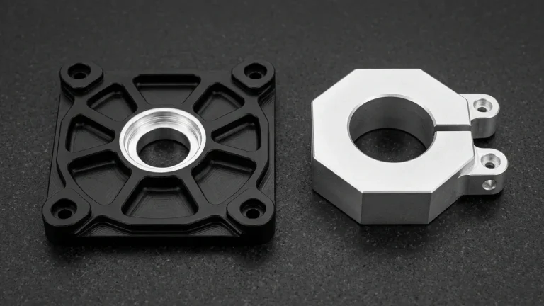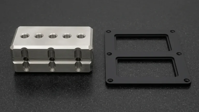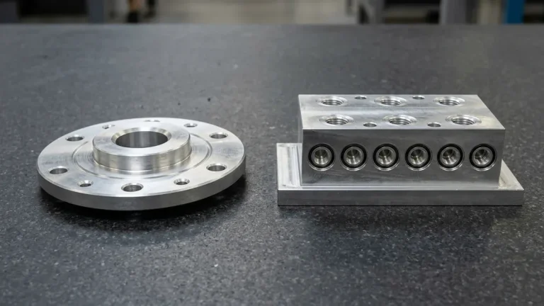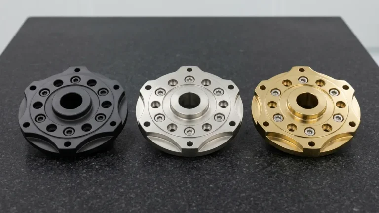
Rigorous aerospace industry prototyping serves as the foundational validation pillar for flight-critical assemblies. Consequently, detecting structural flaws during prototype validation mitigates exorbitant aerospace airworthiness verification delays and redesign expenses.
Modern aerospace programs demand zero-defect manufacturing across engine, structural, and interior flight hardware. Furthermore, partnering with an experienced aerospace manufacturing facility ensures complete material traceability and aerospace-grade quality protocols compliance.
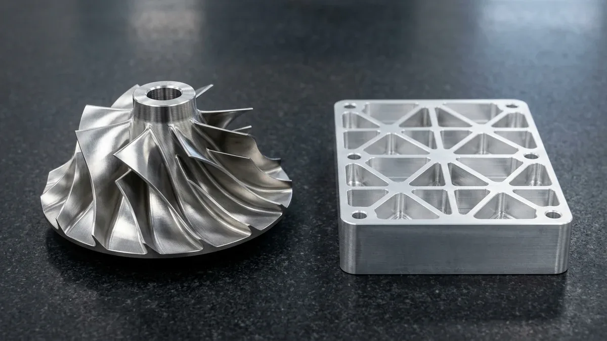
Complex structural airframe components require multi-axis cutter access. Specifically, deploying high-speed 3-axis and 4-axis VMCs alongside simultaneous 5-axis CNC machining centers delivers continuous compound curve contours and critical mating features within ±0.010 mm (±0.0004″) tolerances.
1. Strategic Roles of Aerospace Prototyping
Aerospace prototypes validate aerodynamics, structural load paths, and thermal resistance before volume production. For example, scale models undergo wind tunnel aerodynamic testing to quantify boundary layer drag.
In addition, structural prototypes endure cyclic fatigue and vibration qualification. Therefore, stress engineers verify finite element load predictions under real mechanical forces.
Functional avionics enclosures also undergo electromagnetic interference shielding tests. Ultimately, comprehensive prototype validation secures regulatory aerospace airworthiness verification.
2. Aerospace Prototyping Processes Comparison
Aerospace engineers select rapid manufacturing processes based on mechanical loads and production speed. To illustrate, review the process comparison matrix below:
| Manufacturing Method | Dimensional Tolerance | Surface Roughness (Ra) | Lead Time | Optimal Aerospace Application |
|---|---|---|---|---|
| 3/4/5-Axis CNC Machining | ±0.010 mm to ±0.020 mm | 0.4 to 0.8 μm | 4 to 8 business days | Structural bulkheads, engine mounts, landing gear |
| DMLS / SLM Metal 3D Printing | ±0.050 mm to ±0.100 mm | 3.2 to 6.3 μm | 4 to 8 business days | Turbine fuel nozzles, conformal cooling ducts |
| Investment Casting Patterns | ±0.100 mm to ±0.250 mm | 1.6 to 3.2 μm | 2 to 4 Weeks | High-pressure turbine blades, exhaust diffusers |
| Precision Sheet Hydroforming | ±0.080 mm to ±0.150 mm | 0.8 to 1.6 μm | 7 to 12 business days | Nacelle skins, exhaust heat shields, ducting |
3. Core Material Selection for Flight Hardware
Aerospace materials must endure extreme pressure gradients and thermal shocks. Specifically, materials engineers prioritize four high-performance alloy and polymer families.
1. Titanium Alloys (Ti-6Al-4V)
Titanium provides unmatched strength-to-weight efficiency and superior galvanic corrosion resistance. Consequently, aircraft manufacturers specify titanium for high-stress wing spars and landing gear pivots.
In addition, titanium maintains mechanical properties up to 400 degrees Celsius. Therefore, it resists thermal degradation in jet engine bypass ducting.
2. High-Strength Aluminum 7075-T651
Zinc-alloyed 7075 aluminum offers yield strength comparable to mild structural steels. However, its low density yields massive weight savings across primary fuselage ribs.
Furthermore, stress-relieved T651 temper eliminates residual stresses during deep pocket milling. Thus, thin-walled aerospace housings maintain dimensional stability after machining.
3. Nickel Superalloys (Inconel 718)
Turbine combustion zones exceed temperatures of 700 degrees Celsius. Consequently, standard engineering steels suffer rapid creep and surface oxidation.
Inconel 718 maintains tensile integrity under severe thermal cycling. Specifically, CNC milling and EDM spark erosion handle this work-hardening superalloy effectively.
4. Aerospace Prototyping Alloy Specifications
Selecting the optimal flight material requires balancing density against yield strength. To illustrate, review the mechanical properties below:
| Aerospace Material | Density (g/cm³) | Yield Strength (MPa) | Max Service Temp | Typical Subsystem Application |
|---|---|---|---|---|
| Ti-6Al-4V Grade 5 Titanium | 4.43 | 880 | 400 °C | Wing attachment lugs, landing gear cylinders |
| Aluminum 7075-T651 | 2.81 | 503 | 120 °C | Airframe ribs, hydraulic manifolds, brackets |
| Inconel 718 Superalloy | 8.19 | 1100 | 700 °C | Combustor liners, turbine exhaust nozzles |
| 17-4 PH Stainless Steel (H900) | 7.75 | 1170 | 315 °C | Actuator shafts, aerospace fasteners, hinges |
| PEEK Carbon Fiber (PEEK-CF30) | 1.38 | 210 | 250 °C | Avionics trays, lightweight cabin brackets |
5. Technical Engineering FAQ
Aerospace prototyping verifies aerodynamic performance, structural integrity, and flight clearances under real conditions. Consequently, early physical testing eliminates catastrophic failure risks before full documentation.
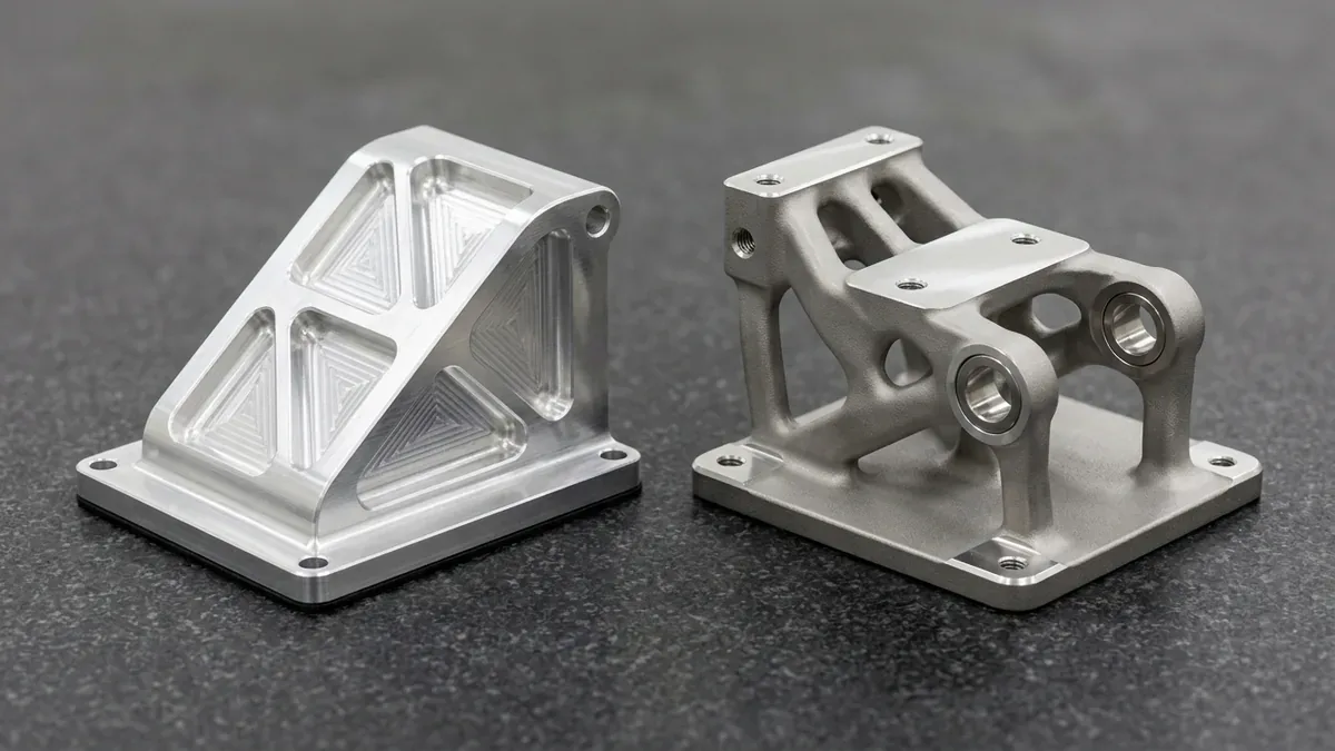
5-axis CNC delivers superior surface finish and tighter dimensional accuracy down to ±0.010 mm (±0.0004″) from solid wrought billet. In contrast, DMLS additive manufacturing produces complex organic lattices and internal channels impossible to mill directly.
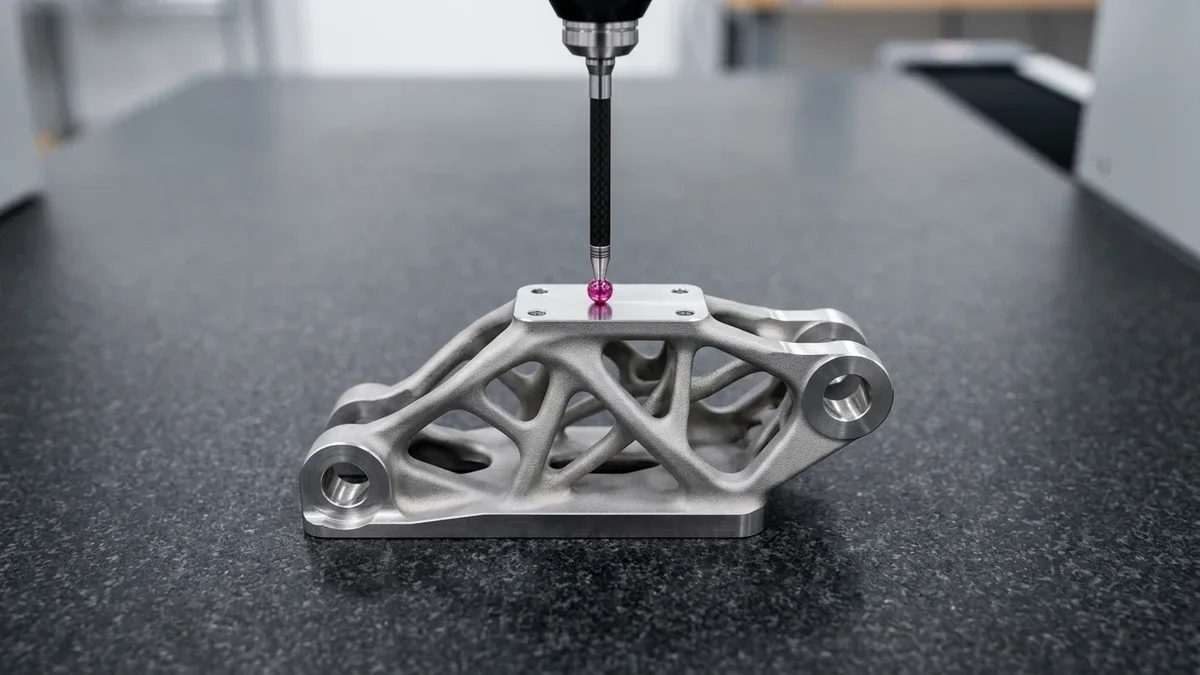
Validation requires tactile Zeiss Bridge CMM verification on CNC-machined metal datums (available upon request), 2.5D optical vision metrology, and traceable raw material Mill Test Reports (MTRs). Furthermore, our quality team provides comprehensive First Article Inspection (FAI) dimensional reports upon request.
Accelerate Flight-Hardware Validation with Precision Aerospace Prototyping
Validate complex airframe brackets, turbine housings, and flight manifolds with 5-axis CNC machining and DMLS metal prototyping. Upload your 3D CAD assemblies (STEP/IGES) for a comprehensive DFM and tolerance review.
Request an Aerospace Prototyping & CNC DFM Review