In precision CNC machining and advanced manufacturing, holemaking represents one of the most critical, frequent, and demanding operations. Statistically, drilling accounts for over 25% to 35% of all metal-cutting machining time in precision contract manufacturing. However, selecting among the diverse types of drill bits is far more complex than choosing a nominal hole diameter.
A mismatched drill bit geometry, improper substrate material, or incorrect canned cycle can lead to catastrophic drill walking, poor hole circularity, extreme exit burrs, work-hardening, or premature catastrophic tool snapping deep inside high-value aerospace manifolds.
At AS Prototypes, our CNC engineering teams deploy precision-engineered drilling strategies—ranging from micro-drilling (Ø < 0.5 mm) to 30×D deep-hole gundrilling—using calibrated toolholders, through-spindle high-pressure coolant, and advanced PVD coatings. Below is a comprehensive engineering guide to industrial drill bit classifications, geometries, and CNC best practices.
Executive Summary & Engineering Takeaways (BLUF)
- Core Focus & DFM Scope: Actionable shop-floor engineering guidelines for types of drill bits, covering material selection, geometric tolerancing, and defect prevention.
- Achievable Tolerance Envelope: General features hold ISO 2768-mK; critical bearing bores, dowel pins, and mating datums hold ±0.010 to ±0.020 mm (±0.0004″ to ±0.0008″), with Wire EDM/grinding to ±0.005 mm (±0.0002″).
- Machining & Surface Integrity: High-speed 3-axis and 4-axis VMCs (with simultaneous 5-axis for complex contours) delivering as-machined Ra 0.8 µm (32 µin) to Ra 0.4 µm (16 µin) per ASME B46.1.
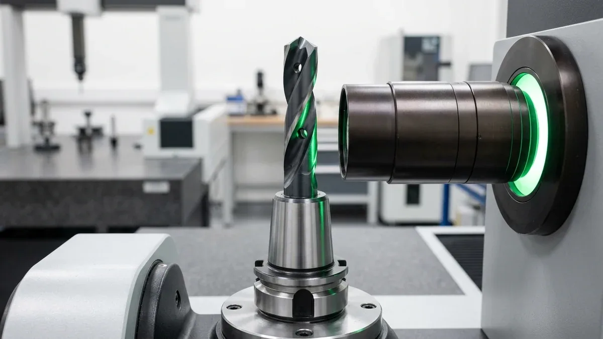
- Metrology & Process Control: On-machine spindle probing paired with 20°C (68°F) climate-controlled Zeiss CMM coordinate verification and calibrated Go/No-Go plug/ring gauges.
- Ex-Factory Turnaround: 4 to 8 business days for as-machined rapid prototypes; 7 to 12 business days for anodized, plated, or multi-operation production runs (excluding 3–5 days air transit).
Article Engineering Navigation
1. Industrial Classification: Primary Types of Drill Bits in CNC Machining
While consumer-grade drilling often relies on generic high-speed steel (HSS) twist bits, industrial CNC machining demands purpose-engineered holemaking tools optimized for rigidity, chip evacuation, and thermal management.
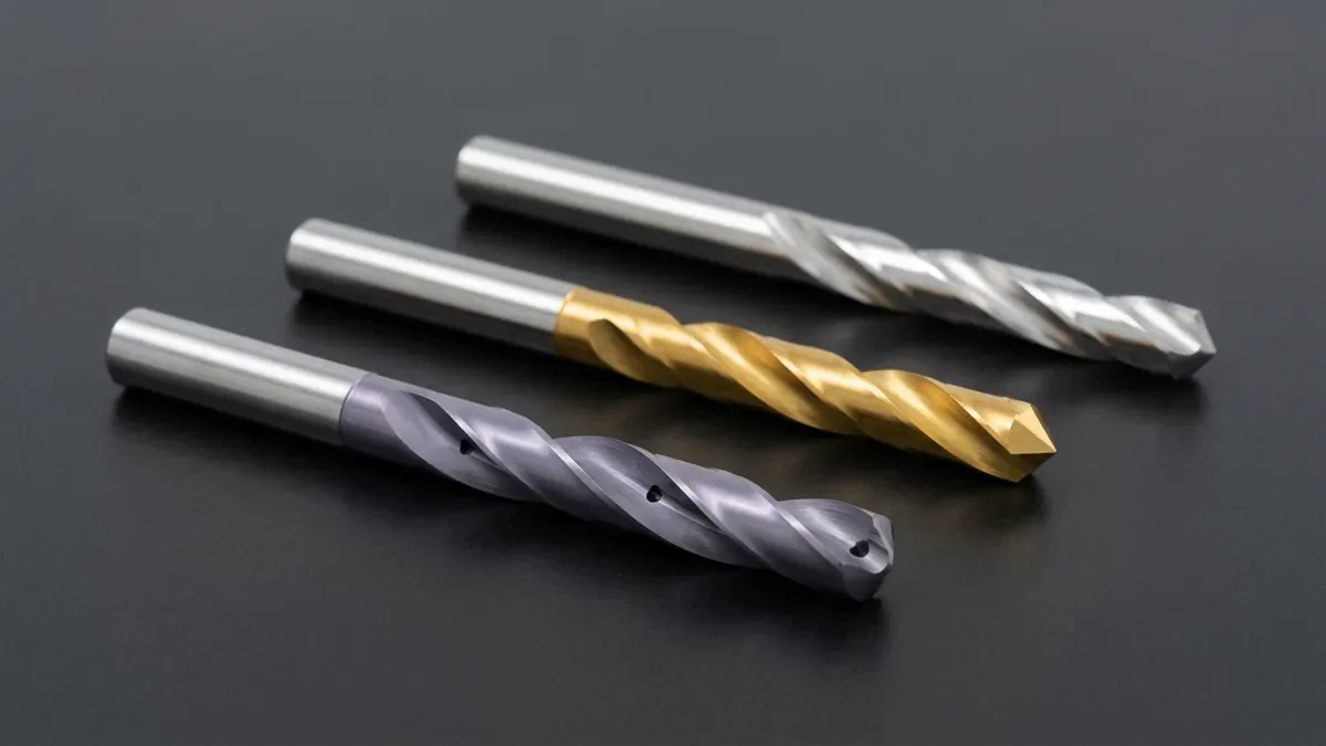
1. Solid Carbide Twist Drills (Jobber & Stub Length)
Solid sub-micron grain tungsten carbide drills are the workhorses of high-productivity CNC machining centers. Delivering extreme torsional rigidity (E ≈ 600 GPa, nearly triple that of steel), carbide drills allow cutting speeds (Vc) 3 to 5 times faster than HSS. Modern carbide drills incorporate specialized 140° self-centering point geometries, eliminating the need for center spotting while maintaining true position tolerances within ±0.02 mm.
2. Indexable Insert Drills (U-Drills)
Designed for medium-to-large diameter holemaking (Ø14 mm to Ø80+ mm), indexable drills feature a hardened tool steel body equipped with replaceable carbide inserts. Typically, an inboard insert cuts the central core while an outboard insert machines the outer circumference. Indexable drills operate without peck cycles at high feed rates, dramatically reducing cycle times in roughing billets and structural plate fabrication.
3. High-Speed Steel (HSS) & Cobalt (M35 / M42) Drills
Formulated with 5% (M35) to 8% (M42) cobalt content, cobalt drill bits retain high hot hardness (red hardness) up to 600°C. While less rigid than solid carbide, cobalt drills exhibit exceptional fracture toughness. They are the preferred solution in unstable setups, deep cross-hole intersections, manual prototyping, and machining tough austenitic stainless steels (304/316L) where intermittent shock loads would chip brittle carbide flutes.
4. Gundrills & Single-Lip Deep-Hole Drills
When hole depth-to-diameter ratios exceed 10 × D up to 50 × D or higher, conventional twist drills fail due to chip pack and wandering.
Gundrills utilize an asymmetric single-lip cutting edge with a V-shaped flute and an internal high-pressure coolant channel (up to 70 to 100 bar). The coolant forces chips out along the external V-flute while burnishing pads on the tool head support the drill against the hole wall, achieving bore straightness of 0.01 mm per 100 mm depth and mirror-like surface finishes (Ra < 0.4 μm).
5. Step & Combination Form Drills
Step drills feature two or more cutting diameters ground into a single body. In precision CNC production, combination step drills perform multiple operations in a single Z-axis stroke: drilling the pilot hole, countersinking a 90° screw seat, and counterboring a bolt head recess. Consolidating operations eliminates tool changes, reduces spindle indexing delays, and guarantees concentricity between the hole and the chamfer.
6. Spotting & Center Drills
Spotting drills feature short, ultra-stiff flutes designed to create an accurate dimple that guides subsequent drills. Crucial Engineering Note: When spotting for a modern 140° solid carbide drill, the spot drill point angle must be equal to or flatter than the drill point (e.g., 142° or 145°). Using a traditional 90° spot drill forces the fragile outer corners of a 140° carbide drill to contact the metal first, causing instant micro-chipping and hole wandering.
7. Micro Drills (Ø 0.1 mm to Ø 1.0 mm)
Used extensively in medical devices, semiconductor test sockets, and microfluidic manifolds, micro-drills demand ultra-high spindle speeds (20,000 to 60,000 RPM) and total indicator runout (TIR) maintained strictly within 0.005 mm (0.0002 in) using thermal shrink-fit or high-precision hydraulic chucks.
2. Critical Drill Bit Anatomy & Cutting Tool Geometries
The operational performance, thrust force, and tool life of a drill bit are dictated by microscopic geometric features engineered into its tip and flutes:
- Point Angle (118° vs. 135° vs. 140°):
- 118° Point: Conventional angle for general-purpose HSS drilling in mild steel, brass, and aluminum. Forms longer cutting lips that ease penetration in softer materials.
- 135° Split-Point: Standard for tough alloy steels and stainless steels. Flatter angle shortens the cutting lips, distributing cutting forces and reducing workpiece work-hardening.
- 140° Point: Universal standard for high-performance solid carbide CNC drills. Maximizes tip mass behind the cutting edge and provides optimal entry dynamics in high-speed machining.
- Chisel Edge & Web Thinning: The central web connects the two flutes. Because the rotational velocity at the dead center is zero, the chisel edge does not cut—it extrudes metal under immense thrust pressure. Modern high-performance drills utilize split-point web thinning (R-thinning or S-thinning) to transform the chisel edge into active cutting edges, slashing axial thrust force by 40% to 50% and eliminating drill walking.
- Helix Angle (Spiral Flute Angle):
- Slow Helix (10° to 15°): High torsional rigidity, ideal for brass, bronze, cast iron, and thermoset plastics where powdery chips require minimal lifting force.
- Standard Helix (25° to 30°): Balanced all-around geometry for alloy steels, carbon steels, and general machining.
- Quick/High Helix (35° to 40°): Essential for long-chipping ductile materials like 6061-T6 aluminum, copper, and austenitic stainless steels to accelerate chip evacuation out of deep holes.
- Margin Configuration (Single vs. Double Margin):
- Single Margin: Lower rubbing friction and lower heat generation, suited for high-temperature alloys and deep holes.
- Double Margin: Provides 4-point cylindrical guidance along the hole wall. Delivers exceptional hole roundness, eliminates bell-mouthing, and holds tight IT8–IT9 (ISO H8–H9) diametrical tolerances directly while providing an ideal concentric pre-bore for precision ISO H7 reaming.
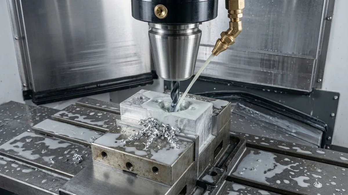
- Through-Spindle Internal Coolant Channels (TSC): Helical coolant holes routed through the carbide blank deliver high-pressure cutting fluid (30 to 70 bar) directly to the cutting zone. TSC prevents thermal shock, lubricates margins, and hydraulically blasts chips up the flutes.
3. Advanced PVD Wear Coatings for Industrial Drill Bits
Modern PVD (Physical Vapor Deposition) thin-film coatings multiply drill tool life and allow higher cutting speeds by providing a thermal barrier and lowering friction coefficients (μ):
4. CNC Drilling Dynamics: Programming Cycles & Parameter Control
Achieving micron-accurate, burr-free holes requires matching toolpath kinematics to the material and aspect ratio:
1. Selecting the Optimal Canned Cycle
- G81 (Standard Direct Drilling): Feeds continuously to final depth without pauses. Recommended exclusively for shallow holes (Depth ≤ 3 × D) when using solid carbide through-coolant drills. Direct drilling prevents work-hardening at the hole bottom.
- G82 (Drilling with Dwell): Incorporates a programmed dwell (P) at the bottom of the stroke to clean up counterbores, blind hole bottoms, and establish a flat seating surface.
- G73 (High-Speed Chip Break Peck Cycle): Retracts the drill by a tiny increment (e.g., 0.5 mm to 1.0 mm) without exiting the hole. This fractures continuous stringy chips in ductile steels without flooding the flutes with exterior air, maintaining fast cycle times.
- G83 (Deep Hole Full Retract Peck Cycle): Completely withdraws the drill to the reference clearance plane (R) between pecks. Mandatory for deep holes (Depth > 5 × D) with non-coolant drills to evacuate packed chips and allow exterior coolant to re-flood the hole.
2. Runout (TIR) Management in Toolholders
Total Indicator Reading (TIR) runout measured at the drill tip must remain under 0.005 mm (0.0002 in). Excessive runout causes one cutting lip to carry the entire mechanical load, resulting in oversized, triangular (three-lobed) holes and premature corner chipping. AS Prototypes strictly pairs solid carbide drills with hydraulic expansion chucks or thermal shrink-fit toolholders rather than standard ER collet chucks.
3. Breakthrough Dynamics & Exit Burr Minimization
As a drill breaks through the exit face of a plate, workpiece axial stiffness collapses. The drill can grab into the remaining thin metal web, causing spindle deceleration, edge chipping, and massive rollover exit burrs. Our CAM programming automatically applies a 50% feed rate reduction across the final 1.5 mm of drill breakthrough, ensuring clean hole exits and slashing secondary deburring time.
Shop-Floor Cost-Tolerance Trade-Offs & When NOT to Over-Specify
When releasing production drawings for precision CNC drilled and bored components, applying blanket ±0.010 to ±0.020 mm (±0.0004″ to ±0.0008″) tolerances across non-mating clearance features increases machining cycle time by 2.0× to 3.5× without improving functional assembly. Our DFM engineers recommend specifying ISO 2768-mK on general structural walls while isolating tight GD&T callouts strictly to functional bearing bores, dowel pins, and sealing interfaces.
In our Shenzhen facility, prismatic 3-axis and 4-axis vertical machining centers (VMCs) with contoured soft jaws handle 80%+ of structural setups with maximum rigidity and cost efficiency, reserving simultaneous 5-axis contouring strictly for compound-angle ports and organic impellers. Every batch undergoes climate-controlled 20°C (68°F) Zeiss CMM verification prior to ex-factory release (4 to 8 business days for raw prototypes; 7 to 12 business days with MIL-A-8625 anodizing or ASTM A967 passivation).
🔗 Related CNC DFM & Metrology Engineering Guides:
To further optimize cycle time and dimensional stability in precision CNC drilled and bored components, combine proper internal corner relief with datum-based coordinate inspection. Consult our shop-floor engineering guides on Maintaining Dimensional Stability in Thin-Wall Machining, Eliminating Sharp Internal Corners & Tool Deflection, and Precision CMM Metrology & GD&T Verification.
5. Technical Engineering FAQ
Tungsten carbide possesses immense compressive strength but lower tensile and shear strength than high-speed steel. A flatter 140° point angle provides greater carbide substrate mass directly behind the cutting lips, distributing axial cutting pressure evenly and preventing premature cutting edge fracture during high-feed CNC entry.
Gundrilling is specified when hole depths exceed 10 to 15 times the diameter (L/D > 10–15), or when stringent hole straightness (under 0.01 mm per 100 mm) and high-quality internal surface finishes (Ra < 0.4 μm) are mandatory. Conventional twist drills wander significantly and pack chips at extreme aspect ratios.
Yes, for shallow holes (L/D ≤ 3), using high-cobalt drills (M42) or coated carbide drills with flood coolant and a G73 chip-breaking cycle. However, for depths beyond 3 × D, 316L work-hardens rapidly under intermittent cutting. Through-spindle high-pressure coolant (TSC) is strongly recommended to maintain continuous tool engagement and prevent work-hardening.
Drill margins act as burnishing and guiding surfaces along the hole wall. Single-margin drills offer lower friction in difficult alloys, whereas double-margin drills provide 4-point radial guidance, minimizing drill deflection and holding tighter diametrical tolerances (typically IT8–IT9 / ISO H8–H9 directly off the drill, while critical ISO H7 dowel and bearing bores receive a final reaming or boring pass).
A 142° spot drill ensures subsequent 140° carbide drills engage first at the chisel center point rather than the fragile outer cutting corners, preventing tool chipping, wander, and bell-mouthing.
Partner with Our Precision CNC Machining & Engineering Team
Eliminate tool deflection, residual stress distortion, and tolerance stack-up risks before production begins. Upload your 3D CAD files (STEP/IGES) and 2D GD&T drawings for a comprehensive shop-floor DFM review and custom quotation.
Upload 3D CAD for Engineering DFM & RFQ