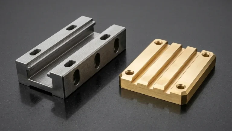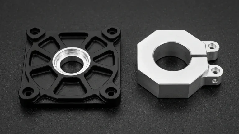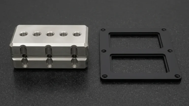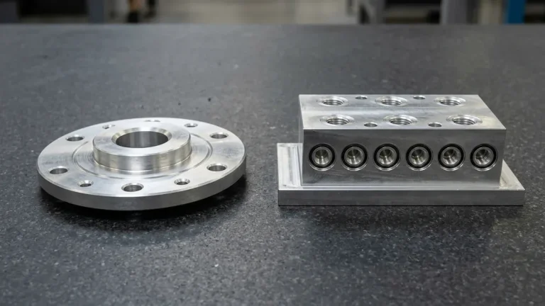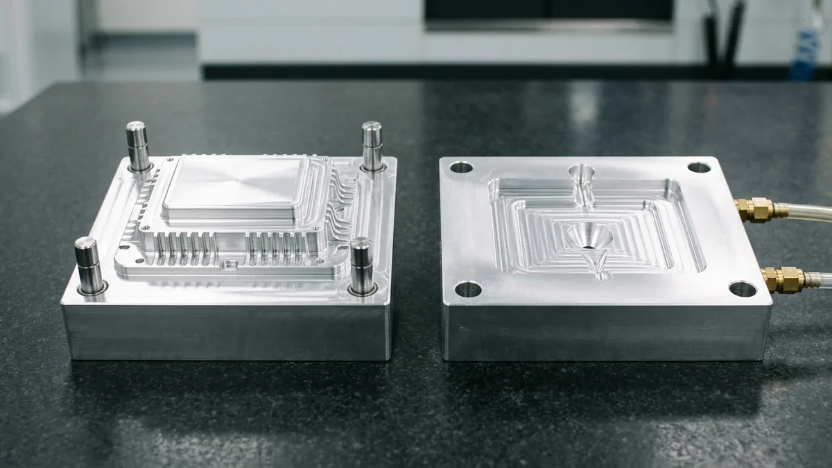
Plastic injection molding remains the definitive manufacturing process for scalable, high-precision plastic components across the automotive, medical, industrial electronics, and consumer hardware sectors. However, traditional production tooling often demands extensive upfront capital expenditures and prolonged lead times. At AS Prototypes, manufacturing custom components with our in-house injection molding services and agile rapid tooling bridges this critical gap—delivering functional molded prototypes and low-to-mid volume production parts with verified mechanical properties in 18 to 35 business days.
This technical guide examines the metallurgical, mechanical, and rheological fundamentals of rapid tooling and production injection molding in China. From selecting between high-strength aluminum and pre-hardened tool steels to conducting comprehensive Moldflow simulations, mechanical side-action slide design, high-speed CNC cavity milling, and coordinate metrology verification, we detail how modern toolrooms achieve micro-inch surface finishes and tight dimensional tolerances.
- 1. Tooling Classification: Modular Rapid Tooling vs. Production Tooling
- 2. Mold Base Standards & Mechanical Side-Action Mechanisms
- 3. Design for Manufacturability (DFM) & Rheological Moldflow Simulation
- 4. Precision Mold Machining: High-Speed CNC Cavity Milling
- 5. Intricate Details & Deep Ribs: Sinker EDM Erosion
- 6. Automated Injection Molding Production & T1 Sampling
- 7. Quality Assurance & Tooling Metrology for Molded Parts
- 8. Technical Engineering FAQ
1. Tooling Classification: Modular Rapid Tooling vs. Production Tooling
The primary architectural decision in injection molding tooling is determining the tool classification based on anticipated production volume, resin abrasiveness, part complexity, and target turnaround schedule. Tooling broadly divides into rapid prototype tooling (utilizing Master Unit Die modular frames or standalone aluminum/soft-steel inserts) and hardened steel multi-cavity production molds.
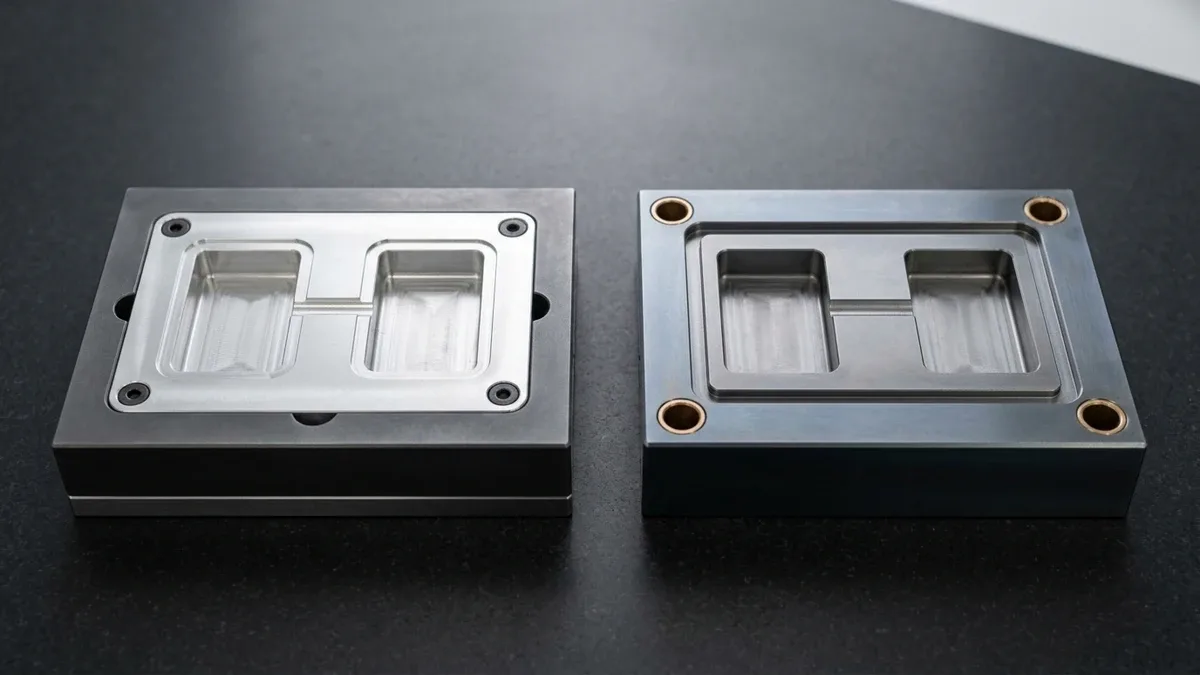
For functional prototyping, bridge tooling, and market validation (runs of 500 to 20,000 units), rapid tooling utilizes standardized Master Unit Die (MUD) bases. In this modular system, a permanent heavy-duty steel mold frame remains in the shop, while custom core and cavity inserts are rapidly machined from 7075-T651 aluminum or pre-hardened P20 steel (28–32 HRC). By machining only the interchangeable cavity inserts and clamping them with precision toe clamps, tooling costs are reduced by 40% to 65% compared to dedicated production tooling.
| Tooling Class | Core & Cavity Material | Typical Shot Life | Standard Turnaround | Recommended Application |
|---|---|---|---|---|
| Rapid Prototype Tooling (Class 105) | AlQC-10 / 7075-T651 Aluminum | 500 – 5,000 shots | 18 – 25 Business Days | Functional prototypes, design validation, non-abrasive resins (ABS, PP, PC) |
| Bridge Tooling (Class 104) | P20 / NAK80 Pre-hardened Steel | 10,000 – 50,000 shots | 20 – 30 Business Days | Low-volume production, bridge-to-market batches, filled polymers |
| Medium Production (Class 103) | H13 / 1.2344 / 420 Stainless (Through-hardened) | 100,000 – 500,000 shots | 25 – 35 Business Days | Mid-volume production runs, cosmetic exterior housings, engineering polymers |
| High-Volume Production (Class 101/102) | H13 (48–52 HRC) / S136 Mirror Stainless | 1,000,000+ shots | 25 – 35 Business Days | High-speed multi-cavity automated packaging, medical devices, automotive components |
2. Mold Base Standards & Mechanical Side-Action Mechanisms
High-precision injection molds rely on standardized mold base platforms (such as DME, HASCO, and LKM standards) to guarantee dimensional repeatability, interlock rigidity, and rapid spare-part serviceability. Four precision-ground cylindrical leader guide pins and matching bronze-plated guide bushings maintain absolute alignment between the stationary platen (A-plate) and moving platen (B-plate) under high clamping tonnages.
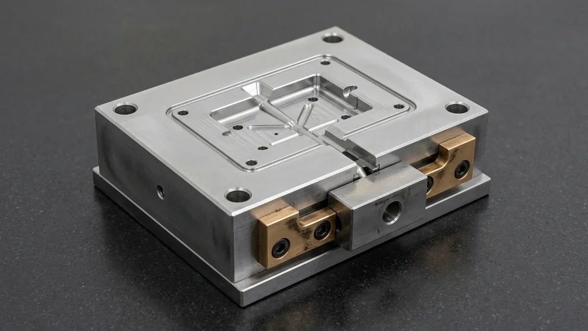
When plastic components feature lateral openings, side louvers, snap fits, or I/O connector ports, they create geometric undercuts that prevent straight-pull mold opening. To release these undercuts without parting line damage, AS Prototypes incorporates precision mechanical side-action slide assemblies (sliders) and lifters:
- Mechanical Angle Pins (Horn Pins): Case-hardened cylindrical pins set at an angle of 15° to 25° relative to the mold draw direction drive the slide outward during the mold opening stroke.
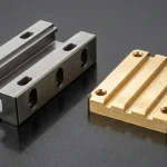
- Wear Plates and Bronze Gibs: High-wear sliding contact surfaces utilize aluminum-bronze wear plates with cross-hatched graphite oil-retention lubrication grooves to eliminate galling over hundreds of thousands of cycles.
- Heel Locking Blocks: Heavy-duty angled steel wedge blocks mounted on the stationary plate securely lock behind the slide during clamping, resisting the extreme hydrostatic injection pressure exerted on the slide face.
- Internal Mechanical Lifters: Guided ejector lifters angled at 5° to 12° travel upward with the ejector plate while simultaneously moving inward to release internal snaps and threaded bosses.
3. Design for Manufacturability (DFM) & Rheological Moldflow Simulation
Successful injection molding depends on rigorous upfront engineering analysis. Before cutting steel or aluminum, our senior tooling engineers perform comprehensive Design for Manufacturability (DFM) reviews and finite-element Moldflow rheological simulations to predict melt behavior, optimize cooling, and mitigate common molding defects.
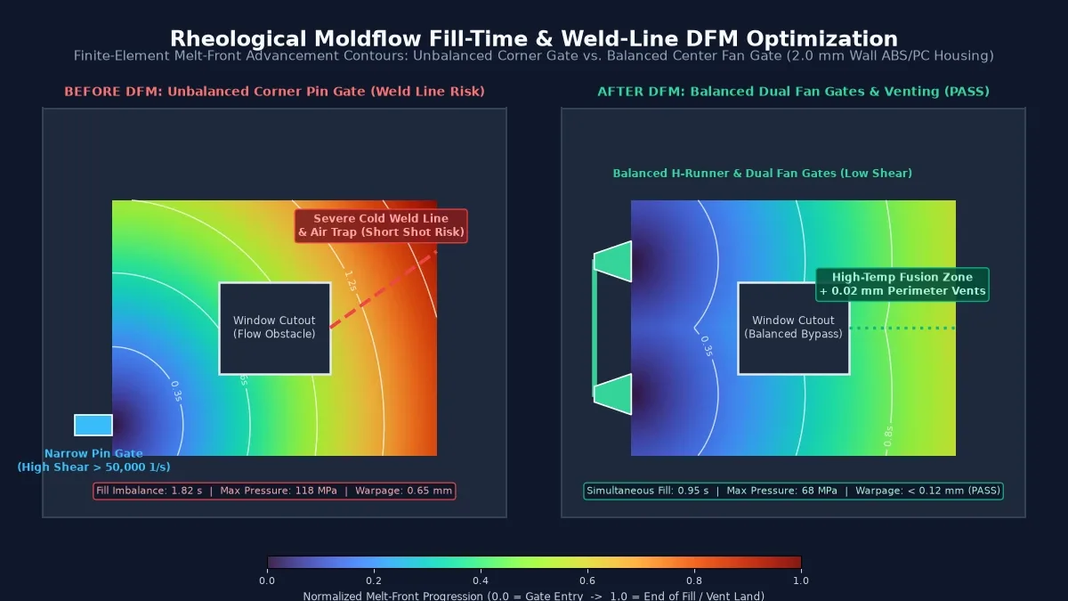
During DFM and rheological simulation, four critical manufacturing criteria are systematically evaluated:
- Nominal Wall Thickness & Uniformity: Wall thickness must remain consistent across the component geometry (typically 1.5 to 3.0 mm for standard engineering plastics like ABS and PC). Thick structural bosses and ribs must be cored out to 40%–60% of the adjacent nominal wall thickness to eliminate sink marks and internal vacuum voids.
- Draft Angles for Clean Part Demolding: A minimum draft angle of 1.0° to 1.5° per side is applied to all vertical shut-off surfaces. For textured exterior surfaces (such as SPI B-2 or Mold-Tech MT-11010 textures), draft angles are increased by 1.0° for every 0.025 mm of texture depth to prevent scuff marks during automated part ejection.
- Gate Placement & Melt Front Progression: Moldflow simulation evaluates edge gates, sub-gates, and hot runner tips to ensure balanced volumetric fill, eliminating premature freeze-off and positioning knit lines (weld lines) away from high-stress structural features.
- Conformal & Baffled Cooling Line Optimization: Cooling accounts for up to 70% of the total injection cycle time. Strategic placement of cooling channels ensures uniform heat extraction across core and cavity halves, preventing differential shrinkage and part warpage.
4. Precision Mold Machining: High-Speed CNC Cavity Milling
Once CAD designs and Moldflow analyses are validated, mold fabrication commences. Precision CNC milling forms the primary volumetric core and cavity geometry from solid blocks of pre-hardened or through-hardened tool steel.
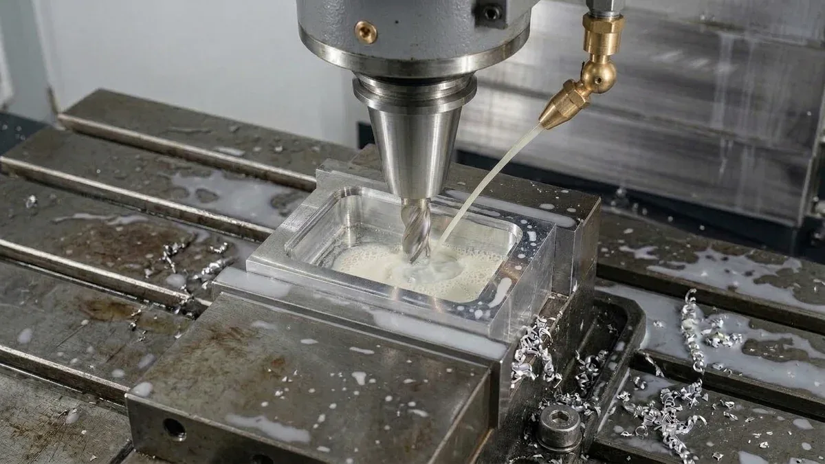
Our in-house CNC machining facilities utilize high-speed vertical machining centers equipped with 18,000 to 30,000 RPM spindles and high-rigidity HSK toolholding. Advanced solid carbide ball-end mills and high-feed cutters sculpt complex 3D contours under continuous high-pressure flood coolant mist, maintaining positional tolerances within ±0.010 mm and surface finishes down to Ra 0.4 µm directly from the cutter path.
5. Intricate Details & Deep Ribs: Sinker EDM Erosion
While high-speed CNC milling excels at 3D contouring, physical tool radius limitations make it impossible for circular rotating end mills to cut sharp internal square corners or high-aspect-ratio deep, narrow stiffening ribs. These micro-features are machined using precision Sinker Electrical Discharge Machining (Sinker EDM).
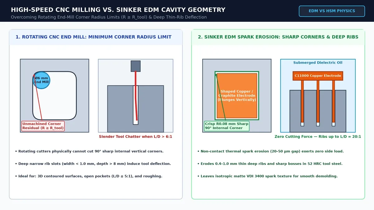
In our precision EDM department, high-purity tellurium copper (or fine-grain isostatic graphite) electrodes are CNC-milled to the exact negative profile of the required ribs. Clamped securely on the machine table, the mold block is completely submerged under clear dielectric hydrocarbon oil. Controlled high-frequency electrical spark pulses vaporize the microscopic metal particles at the spark gap without mechanical cutting forces, eroding crisp square corners and deep structural ribs with mirror-like accuracy.
6. Automated Injection Molding Production & T1 Sampling
Following mold assembly, hand-fitting, Prussian blue paste contact shut-off verification, and polishing, the complete mold base is mounted onto our modern injection molding press fleet for initial T1 sampling and trial optimization.
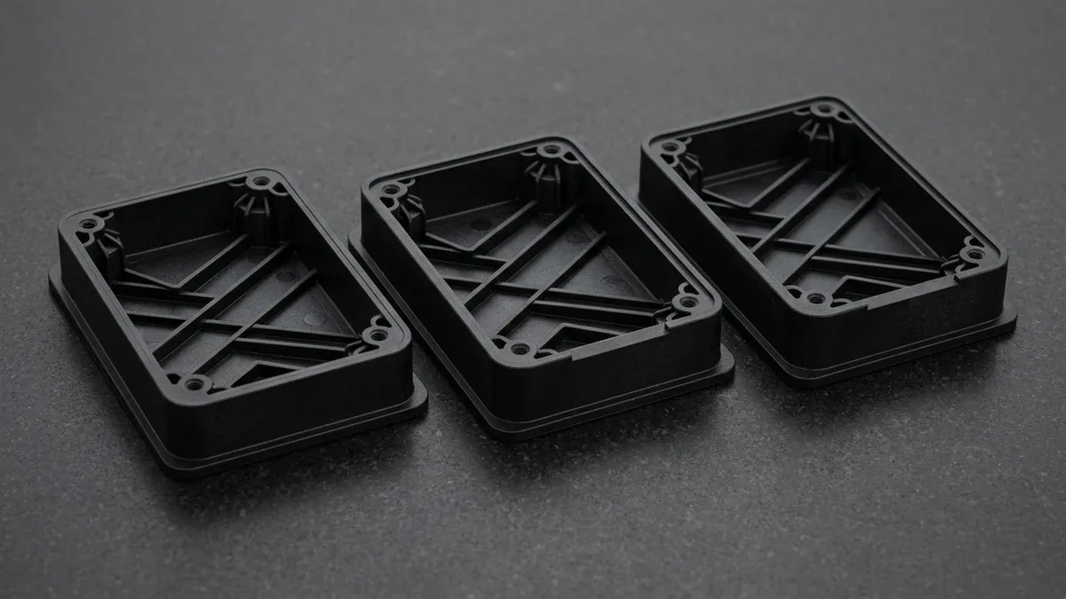
Our production floor operates precision all-electric and servo-hydraulic injection molding presses ranging from 50 tons to 1,200 tons clamping force. Each machine features closed-loop process controllers, multi-zone cavity pressure sensors, and automated 3-axis CNC servo robot part removal. This guarantees precise shot-to-shot consistency, cycle time repeatability, and scratch-free handling of cosmetic engineering components.
7. Quality Assurance & Tooling Metrology for Molded Parts
High-precision injection molding requires strict statistical quality control (SPC) across thousands of consecutive production cycles. Every mold built at AS Prototypes undergoes rigorous toolroom inspection and T1 part validation:
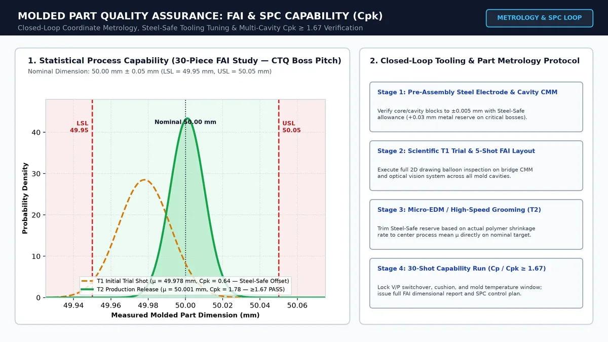
- Parting Line & Shut-Off Surface Blueing: Core and cavity matching surfaces are fitted and tested with Prussian blue paste under clamping tonnage to guarantee 100% full-perimeter shut-off contact, completely eliminating flash.
- First Article Inspection (FAI): Upon T1 mold trial, sample components undergo comprehensive dimensional verification on our coordinate measuring machine (Zeiss CMM with full FAIR and CPK capability reporting available on request), comparing molded geometry against customer 2D GD&T drawings.
- Resin Lot Traceability & Material Inspection: We provide authentic raw polymer batch inspection records, UL94 flammability ratings, and RoHS/REACH compliance documentation on request with every shipment.
- Standardized SPI Surface Finishes: Mold cavities are polished and textured to precise SPI standards—from SPI A-1 optical diamond mirror buffing (3-micron diamond paste for clear PC and PMMA lenses) to SPI B-2 paper finishes and Mold-Tech bead-blast textures.
8. Technical Engineering FAQ
Rapid aluminum (7075-T6) and pre-hardened P20/NAK80 steel tooling fabricated in Shenzhen reduces upfront capital investment by 40% to 65% compared to Western tooling, with T1 molded prototype samples delivered in 18 to 35 business days.
AS Prototypes performs comprehensive DFM and Moldflow simulation prior to tool cutting, ensuring uniform nominal wall thickness (typically 1.5 to 3.0 mm), coring out thick structural bosses to 40% to 60%, applying proper draft angles (1 degree to 2 degrees), and optimizing gate locations to eliminate internal voids.
AS Prototypes provides comprehensive quality documentation tailored to your project requirements. Standard production shipments include raw resin lot traceability data, comprehensive First Article Inspection (FAI) reports, and critical-dimension inspection sheets. For tight-tolerance components, First Article Inspection (FAI) reports with Zeiss CMM verification, CPK statistical process capability data, and spectrophotometer color matching (Delta E < 0.8) are available upon request.
Transition Seamlessly from Rapid Tooling to High-Precision Molding
Optimize cavity life, gate geometry, and part unit economics with our in-house tooling and injection molding engineering team. Upload your 3D CAD models (STEP/IGES) for a comprehensive Moldflow and DFM manufacturability assessment.
Upload 3D CAD for Tooling & Molding DFM Review