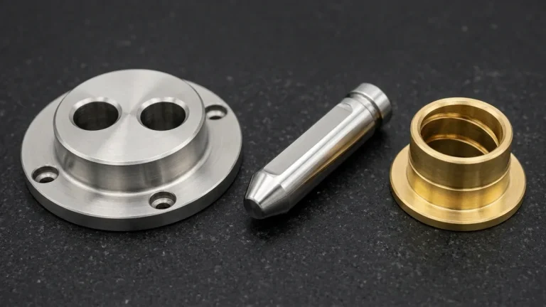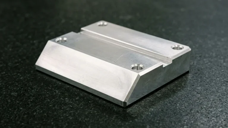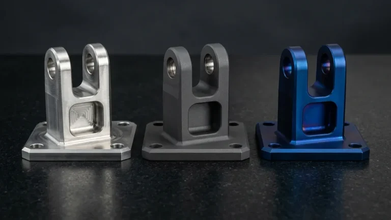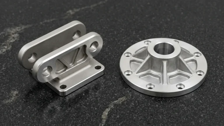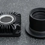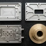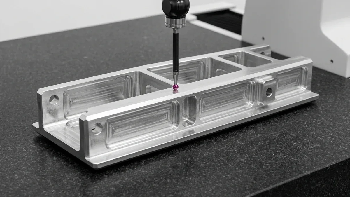
A Coordinate Measuring Machine (CMM) is the definitive spatial metrology system in modern Computer Numerical Control (CNC) manufacturing, verifying complex Geometric Dimensioning and Tolerancing (GD&T) callouts down to ±0.005 mm (±0.0002″). Unlike manual gauges prone to operator parallax, our in-house Zeiss CMM inspection laboratory validates custom CNC machined components against nominal 3D CAD models.
Executive Summary & Engineering Takeaways (BLUF)
- Volumetric Accuracy & Standards: Moving-bridge CMMs calibrated per ISO 10360-2 achieve volumetric length measurement uncertainty down to E0,MPE = 1.2 + L/350 µm across 6061-T6, 7075-T651, 17-4PH, and Ti-6Al-4V components, validating ISO 2768-mK general tolerances and ±0.005 mm (±0.0002″) critical features.
- GD&T & Bonus Tolerance Mastery: Automated 3-2-1 datum alignment evaluates ASME Y14.5 and ISO 1101 true position (⌖), flatness (⏥), perpendicularity (⊥), and surface profile (⌓) while computing Maximum Material Condition (Ⓜ) bonus tolerances.
- Tactile vs. Non-Contact Boundaries: Rigid machined metals undergo ruby tactile probing or continuous scanning, whereas thin sheet metal stampings (0.5–2.0 mm / 0.020″–0.079″), soft elastomers, and polymer prints require non-contact 2.5D Optical Vision Measuring Systems (VMS).
- Climate-Controlled FAI Turnaround: All First Article Inspection (FAI) dimensional reports are executed in a 20 °C ± 1 °C (68 °F ± 1.8 °F) metrology lab within our standard 4–8 business days rapid prototype and 7–12 business days finished part ex-factory turnaround.
Article Engineering Navigation
- 1. Working Principles: Transforming Physical Touch into 3D Spatial Vectors
- 2. Probing Physics: Touch-Trigger, Continuous Scanning & Optical Sensors
- 3. Architectural Configurations of Coordinate Measuring Machines
- 4. Comprehensive Engineering Comparison: CMMs vs. Shop Floor Metrology
- 5. Mastering GD&T Verification on Complex Workpieces
- 6. Metrological Rigor: Calibration, Environmental Control & Traceability
- 7. Technical Engineering FAQ
1. Working Principles: Transforming Physical Touch into 3D Spatial Vectors
A coordinate measuring machine (CMM) is a Cartesian electro-mechanical digitizer that translates physical part geometry into discrete three-dimensional coordinates (X, Y, Z) with sub-micron repeatability down to 0.5 µm (20 µin). Evaluating thousands of spatial points against native STEP or IGES CAD geometry eliminates manual fixture setup drift across multi-datum prismatic and freeform workpieces.
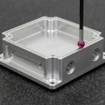
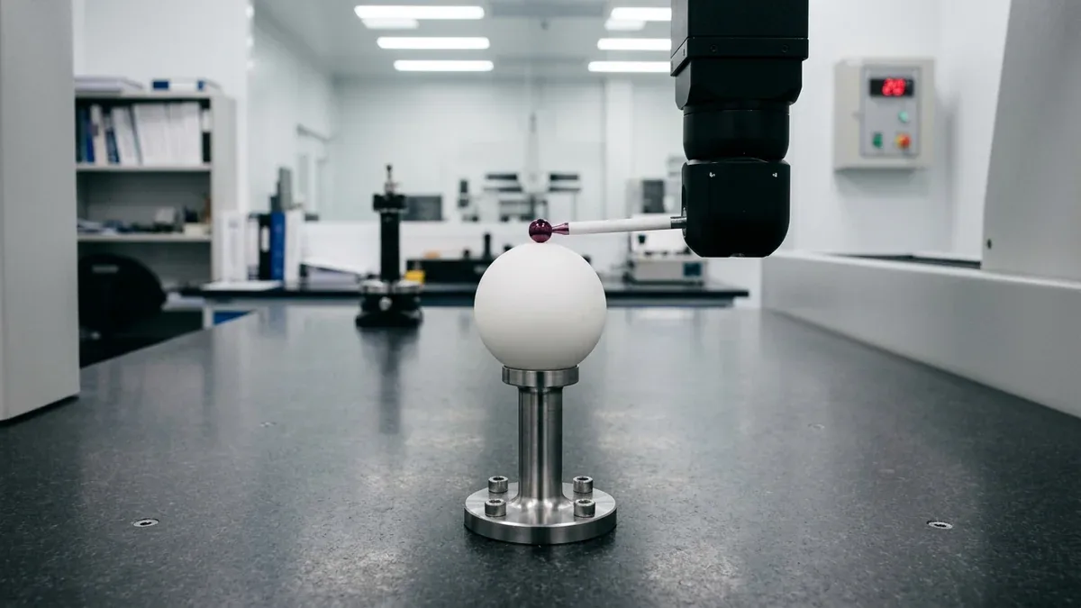
Before measuring production hardware, metrology software (such as Zeiss CALYPSO or PC-DMIS) qualifies the spherical synthetic ruby stylus against a Grade 0 alumina ceramic reference sphere with verified sphericity ≤ 0.05 µm (2 µin). Probing multiple spatial angles maps the effective tip radius and pre-travel lobing offsets (as shown in the automated bridge CMM probe qualification setup below).
The Anatomy of Precision: Four Core Subsystems
Four integrated mechanical and optical subsystems isolate the coordinate measuring machine from shop-floor vibration, friction hysteresis, and thermal drift during micron-level inspection cycles:
- Monolithic Granite Base and Guideways: Naturally aged, precision-lapped Grade 00 black granite provides high structural damping, zero internal residual stress, and a low thermal expansion coefficient (α ≈ 5–6 × 10⁻⁶ /K) compared to cast iron or steel beds.
- Frictionless Pneumatic Air Bearings: Rather than rolling on mechanical ball screws that introduce stick-slip hysteresis, CMM carriages float on pre-filtered compressed air cushions (3 to 5 µm / 0.00012″ to 0.00020″ clearance per ISO 8573-1 Class 1) for frictionless motion.
- High-Resolution Optical Encoders: Zero-expansion Zerodur glass or gold-plated diffraction scales along each orthogonal axis are read by electro-optical sensors, delivering linear scale resolution down to 0.05 µm (2 µin) without mechanical backlash.
- Motorized Indexable Probe Head: Mounted on the vertical Z-axis quill, motorized wrist heads articulate ruby styli across repeatable compound spatial angles (A-axis ±105°, B-axis 360°) to inspect side ports and undercuts in a single workpiece setup.
2. Probing Physics: Touch-Trigger, Continuous Scanning & Optical Sensors
CMM sensor physics governs both point acquisition speed and volumetric measurement uncertainty across discrete tactile triggers, continuous analog scanners, and non-contact optical vision heads. Selecting the wrong sensor architecture for a given surface roughness or wall stiffness introduces cosine lobing errors or elastic part deflection that invalidates tight CNC machining dimensional tolerances.
Touch-Trigger Probing (Kinematic Resistance & Strain Gauge)
Kinematic touch-trigger probes house three spring-loaded cylindrical rods seated in gold-plated V-grooves, or solid-state silicon strain gauges behind a spherical synthetic ruby stylus tip (Ø1.0 to Ø5.0 mm / 0.039″ to 0.197″). Upon surface contact, microscopic stylus deflection breaks the circuit and latches the X, Y, and Z optical scales within sub-microseconds.
Discrete touch-trigger probing excels at verifying planar datum faces, boss heights, and hole centerlines on rigid prismatic blocks. However, for intermediate setup checks directly inside the VMC enclosure before unclamping raw stock, machinists deploy spindle-mounted on-machine inspection (OMI) touch probes to lock work offsets before final laboratory CMM certification.
Continuous Contact Scanning Probing
Continuous analog scanning probes maintain uninterrupted physical contact while sweeping across complex contours, recording 500 to 2,000 spatial coordinate points per second. High-resolution inductive or optical transducers inside the probe head measure real-time stylus deflection across three orthogonal axes (X, Y, Z) with sub-micron linearity.
High-density point clouds prevent the spatial aliasing errors inherent to sparse four-point touch probing. Gaussian spline filtering separates short-wavelength surface roughness (Ra 0.4–1.6 µm / 16–63 µin) from true macro-geometric form errors, accurately reconstructing circularity (○), cylindricity (⌭), and aerodynamic surface profile.
Why Should You Avoid Tactile Bridge CMM Probing on Thin Sheet Metal and Soft Polymers?
Tactile CMM ruby styli exert 0.05 to 0.15 N of mechanical contact force, causing immediate elastic wall bending on thin sheet metal brackets (0.5–2.0 mm / 0.020″–0.079″), flexible 3D-printed polymers, and soft silicone or TPU elastomers.
Furthermore, contact ruby spheres physically scratch optical-grade Single-Point Diamond Turned (SPDT) PMMA lenses (Ra < 5 nm) and cannot enter micro-features below Ø1.5 mm (0.059″). For these compliant or optical parts, our quality lab mandates non-contact 2.5D Optical Vision Measuring Systems (VMS), calibrated pin gauges, and ASTM D2240 / ISO 868 Shore durometers.
3. Architectural Configurations of Coordinate Measuring Machines
Coordinate measuring machine structural kinematics—spanning moving-bridge, fixed-bridge, overhead gantry, and horizontal-arm frames—directly dictates mechanical resonant frequency, volumetric envelope, and maximum permissible error (E0,MPE). Matching frame stiffness to part mass and tolerance width prevents structural bridge yaw from consuming your functional assembly margin.
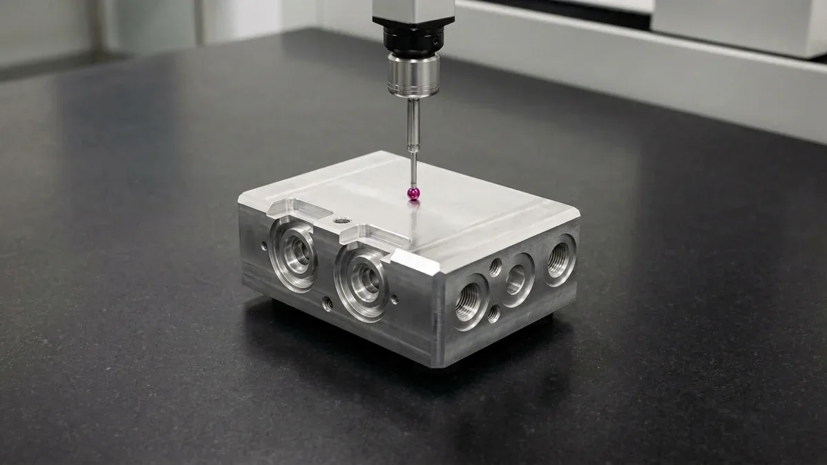
In precision CNC job shops, the moving-bridge CMM is the primary workhorse for prismatic housings and multi-port fluid blocks. Its vertical Z-axis quill positions the ruby ball tip directly onto the machined top datum plane (⏥ 0.010 mm / 0.0004″) of a 6061-T6 aluminum hydraulic valve manifold (see the moving-bridge CMM probing the hydraulic manifold datum plane below).
- Moving-Bridge CMM: A rigid ceramic or anodized aluminum U-bridge travels along granite Y-axis guideways over a stationary workpiece table (500 × 700 × 500 mm to 1,500 × 2,500 × 1,000 mm). It delivers optimal stiffness-to-throughput with volumetric accuracy down to E0,MPE = 1.2 + L/350 µm.
- Fixed-Bridge Metrology CMM: Anchoring the overhead bridge permanently to the monolithic granite base eliminates moving-bridge yaw and angular pitching. Moving only the central workpiece table achieves ultra-low uncertainty (E0,MPE < 0.5 + L/500 µm) for calibrating master ring gauges and surgical bearings.
- Overhead Gantry CMM: Dual elevated support beams carry the X-axis crossbeam above floor-level foundations across spans up to 4,000 × 10,000 × 2,500 mm. This open architecture allows overhead crane loading of heavy aerospace wing spars and automotive stamping dies exceeding 5,000 kg (11,023 lbs).
- Cantilever and Horizontal-Arm CMM: Extending a counterbalanced horizontal ram from a single vertical column provides unobstructed three-sided access for long, slender automotive chassis frames and weldments where a closed bridge would restrict loading, trading micron precision (E0,MPE ≈ 15–40 µm) for reach.
4. Comprehensive Engineering Comparison: CMMs vs. Shop Floor Metrology
Selecting the right inspection platform balances ISO 10360-2 volumetric uncertainty against feature accessibility, part rigidity, and cycle time. The engineering matrix below compares laboratory coordinate measuring machines against shop-floor metrology instruments:
| Metrology System | Volumetric Uncertainty (E0,MPE µm) | Typical Envelope (mm) | Acquisition Rate (pts/s) | Thermal Control Requirement | GD&T Capability (ASME Y14.5) | Recommended Application / When to Choose |
|---|---|---|---|---|---|---|
| Moving-Bridge CMM (Tactile & Scanning) | 1.2 to 2.5 µm + L/350 | 500 × 700 × 500 to 1,500 × 2,500 × 1,000 | 1 to 2,000 pts/s | 20 °C ± 1 °C (68 °F ± 1.8 °F) lab + 4h soak | Full 3D (⌖, ⏥, ⊥, ⌓, ⌭, Ⓜ/Ⓛ) | Best for multi-datum CNC manifolds, bearing housings, and FAI reports holding ±0.010 mm (±0.0004″) |
| Fixed-Bridge Ultra-Precision CMM | 0.4 to 0.8 µm + L/500 | Up to 1,000 × 1,000 × 800 | 500 to 2,000 pts/s | 20.0 °C ± 0.2 °C primary calibration room | Sub-Micron Form & Master Gauge Calibration | Best for calibrating master ring gauges, EDM dies, and ground shafts down to ±0.005 mm (±0.0002″) |
| Overhead Gantry CMM | 3.5 to 6.0 µm + L/250 | 2,000 × 4,000 × 1,500 to 4,000 × 10,000 × 2,500 | 1 to 500 pts/s | 20 °C ± 2 °C + active multi-sensor CTE compensation | Full 3D Large-Envelope Datums & Profile | Best for monolithic aerospace structural ribs, EV battery trays, and heavy automotive stamping dies |
| 2.5D Optical Vision Measuring System (VMS) | 2.0 to 4.5 µm + L/200 (XY) | 300 × 200 × 200 to 500 × 400 × 200 | Instantaneous 2D sub-pixel edge capture | 20 °C ± 1 °C metrology room | 2D Profile, Hole Pitch, True Position & Step Height | Best for thin sheet metal stampings (0.1–3.0 mm), soft silicone/TPU seals, and SLA/SLS/MJF polymer parts |
| On-Machine Spindle Touch Probe (CNC OMI) | 3.0 to 8.0 µm (machine-coupled) | Matches VMC / 5-axis work envelope | 1 to 2 pts/s | In-enclosure coolant thermal stabilization | Datum WCS Alignment, Bore Center & Stock Allowance | Best for in-situ datum setting and semi-finishing tool wear compensation before unclamping the part |
| Calibrated Pin/Plug Gauges & Height Stand | 1.0 to 5.0 µm (pin) / 10 µm (height) | Ø0.5 to Ø50 mm bores / 600 mm height | Manual attribute / single-axis check | 20 °C ± 2 °C shop-floor QC station | ISO 286-2 H7 Go/No-Go Envelope & 1D Step Height | Best for rapid 100% attribute verification of small H7 dowel holes (< Ø6.0 mm) and 6H thread gauges |
5. Mastering GD&T Verification on Complex Workpieces
A coordinate measuring machine executes mathematical Geometric Dimensioning and Tolerancing (GD&T) verification per ASME Y14.5 and ISO 1101 by fitting least-squares or minimum-zone Chebyshev algorithms to 3D point clouds. Virtual datum reference frames eliminate physical clamping distortion while unlocking functional bonus tolerances across multi-axis machined assemblies.
1. Mathematical Datum Alignment (3-2-1 Principle)
Rather than shimming parts manually on sine plates, CMM metrology software locks all six spatial degrees of freedom (three translational: X, Y, Z; three rotational: pitch, roll, yaw) through a sequential 3-2-1 vector alignment:
- Primary Datum Plane (3 Points Minimum): Probing at least three non-collinear points (typically 8–16 distributed points in shop-floor practice) establishes the primary reference plane, locking Z-translation, pitch, and roll while verifying GD&T datum surface flatness (⏥).
- Secondary Datum Line or Axis (2 Points Minimum): Probing a minimum of two points along a reference edge or cylinder axis projects an orthogonal vector onto the primary plane, locking Y-translation and yaw rotation while controlling feature-to-datum perpendicularity (⊥).
- Tertiary Datum Point (1 Point Minimum): Probing a single stop face or orthogonal slot surface establishes the final origin intersection, locking the sixth degree of freedom (X-translation) to complete the deterministic 3D Cartesian coordinate system.
2. True Position with Maximum Material Condition (Ⓜ) & Quantitative Derivation
Evaluating hole pattern true position (⌖) with manual height gauges requires error-prone trigonometric conversions and rejects parts at rigid nominal limits. When a drawing specifies the Maximum Material Condition (Ⓜ) modifier, the CMM measures actual bore size and centerline coordinates simultaneously, dynamically awarding bonus positional tolerance as hole size departs from MMC toward Least Material Condition (LMC).
📐 Shop-Floor Quantitative Derivation: ISO 10360-2 Volumetric Uncertainty & ASME Y14.5 MMC True Position Verification
[Step 1: Define Part Geometry, GD&T Callout & CMM Specifications]
A CNC-milled 7075-T651 aluminum actuator housing features a 4-hole mounting pattern spaced at L = 350 mm (13.780″) referenced to primary Datum A (flatness ⏥ 0.010 mm / 0.0004″), secondary Datum B, and tertiary Datum C. Each bore is specified as Ø12.000 mm (+0.018 / −0.000 mm, ISO 286-2 H7) with true position ⌖ Ø0.025 mm Ⓜ | A | B | C. At 20.0 °C (68.0 °F), our moving-bridge CMM (ISO 10360-2 rating E0,MPE = 1.5 + L/350 µm) measures actual bore size Dactual = 12.012 mm and coordinate offsets ΔX = +0.011 mm, ΔY = −0.012 mm.
[Step 2: Pure Unicode Metrology & GD&T Governing Equations]
• Volumetric Length Measurement Error: E0,MPE = A + (L / K)
• Uncertainty-to-Tolerance Capability Ratio (ISO 14253-1): UTR = (2 × E0,MPE) / Tgeometric ≤ 20%
• Internal Feature MMC Limit & Virtual Condition: DMMC = Dmin, and VC = DMMC − Tgeometric
• Dynamic Bonus & Effective Positional Tolerance: Tbonus = Dactual − DMMC, and Teffective = Tgeometric + Tbonus
• Diametral True Position Error: TPactual = 2 × √(ΔX² + ΔY²)
[Step 3: Step-by-Step Shop-Floor Numerical Substitution]
1. Volumetric Uncertainty over L = 350 mm: E0,MPE = 1.5 + (350 / 350) = 2.5 µm = 0.0025 mm (0.0001″). Capability ratio UTR = (2 × 0.0025 mm) / 0.025 mm = 0.20 (20.0%), confirming a valid 5:1 metrological decision ratio.
2. MMC Virtual Condition & Bonus Tolerance: For Ø12 H7 (+0.018 / −0.000 mm), DMMC = 12.000 mm (0.4724″) and VC = 12.000 − 0.025 = 11.975 mm (0.4715″). At Dactual = 12.012 mm, Tbonus = 12.012 − 12.000 = 0.012 mm, expanding Teffective = 0.025 + 0.012 = 0.037 mm (0.0015″).
3. Actual True Position Deviation: Radial shift rerr = √(0.011² + (−0.012)²) = √(0.000121 + 0.000144) = √0.000265 = 0.01628 mm. Diametral position error TPactual = 2 × 0.01628 = 0.0326 mm (0.0013″).
[Step 4: Engineering Verdict & Shop-Floor Quality Action]
Under rigid Regardless of Feature Size (RFS) inspection, TPactual (0.0326 mm) exceeds the stated 0.025 mm callout and would cause false scrap. With Ⓜ (MMC) evaluation on the CMM, TPactual (0.0326 mm) ≤ Teffective (0.0370 mm) and Dactual (12.012 mm) ≤ DLMC (12.018 mm), leaving 0.0044 mm (4.4 µm) clearance over the Ø11.975 mm virtual condition functional gauge—PASS for FAI release.
3. Profile of a Surface on 5-Axis Complex Contours
For sculptured components produced via simultaneous 5-axis CNC machining—such as Ti-6Al-4V compressor blisks, hydraulic manifolds, and paraboloidal optical reflectors—linear caliper measurements cannot evaluate compound curvature. Continuous CMM scanning traces the 3D surface while computing surface-normal vector deviations against the native STEP CAD spline.
The metrology software generates a color-coded 3D deviation heat map comparing every scanned point against the bilateral profile of a surface tolerance zone (⌓ ±0.010 mm / ±0.0004″). This visual diagnostics map allows CAM engineers to isolate localized tool deflection or rotary trunnion kinematic offsets before batch production.
6. Metrological Rigor: Calibration, Environmental Control & Traceability
Laboratory coordinate measuring machine traceability depends on strict ISO 1 thermal equilibrium at 20.0 °C (68.0 °F), ISO 10360-2 volumetric artifact calibration, and collision-free stylus-to-bore geometry ratios. Without thermal stabilization and proper ruby ball sizing, differential metal expansion and stylus shank grazing corrupt sub-10-micron inspection reports.
In our in-house metrology lab practice, when executing First Article Inspection (FAI) dimensional verification on 7075-T651 aerospace manifolds or 17-4PH bearing housings holding ±0.010 mm (±0.0004″), we enforce a 4-hour thermal soak on the Grade 00 granite plate at 20 °C ± 1 °C and maintain a ruby stylus diameter ratio of Dball ≤ 0.5 · Dhole.
- ISO 1 Thermal Equilibrium & SSOT Drift Delegation: All CMM inspections occur at 20 °C ± 1 °C (68 °F ± 1.8 °F) and 45% ± 5% relative humidity. Because uncompensated ΔL = α · L · ΔT thermal expansion adds ~28 µm (0.0011″) across a 300 mm aluminum part over ΔT = 4 °C, see our aluminum thermal drift and residual stress control guide.
- ISO 10360-2 Volumetric Calibration & Stylus Qualification: Annual laser-interferometer and step-gauge verification certifies volumetric length uncertainty (E0,MPE) and probing form error (PFTU). Prior to each shift, multi-angle qualification against a Grade 0 ceramic reference sphere (sphericity ≤ 0.05 µm / 2 µin) compensates for stylus bending and 3D lobing.
- Shop-Floor Troubleshooting (Small-Bore False Ovality & Shank Grazing): Symptom: Tactile CMM reports 0.018 mm (0.0007″) false ovality on a precision-reamed Ø4.0 mm H7 (+0.012 / −0.000 mm) bore. Root Cause: Oversized Ø3.0 mm ruby stylus causes stem-to-lip shank grazing and 3-point kinematic lobing. Corrective Action: Switch to a Ø1.5 mm ruby tip (Dball ≤ 0.5 · Dhole) with 15-point continuous circular scanning and cross-check with calibrated Class X cylindrical pin gauges.
- First Article Inspection (FAI) Dimensional Reporting & Ballooned Drawing Guide
- On-Machine Inspection (OMI) Spindle Probing for CNC Machining
- CNC Machining Tolerances Guide: ISO 2768-mK & Stack-Up Analysis
- GD&T Flatness Symbol (⏥): Datum Surface Control & CMM Verification
- Perpendicularity in GD&T (⊥): Orientation Tolerance & Inspection Guide
7. Technical Engineering FAQ
Our in-house Zeiss bridge CMM laboratory maintains a climate-controlled 20 °C ± 1 °C (68 °F ± 1.8 °F) environment per ISO 1 after a mandatory four-hour part thermal soak. Automated metrology software further applies material-specific thermal expansion coefficients to normalize verified coordinate dimensions within ±0.005 mm (±0.0002″).
Touch-trigger probes capture discrete spatial points via kinematic resistance switches, suiting prismatic datum planes and standard hole centers under ISO 2768-mK. Conversely, continuous analog scanning sweeps 500 to 2,000 points per second across contoured surfaces to verify true circularity, cylindricity, and profile within ±0.010 mm (±0.0004″).
When ASME Y14.5 drawings specify the Maximum Material Condition (MMC) symbol, the CMM measures both actual bore diameter and centerline coordinates simultaneously. Any departure from the smallest permissible hole diameter toward Least Material Condition dynamically adds bonus positional tolerance while protecting the virtual condition assembly boundary.
Tactile ruby styli exert 0.05 to 0.15 N of mechanical contact force that elastically deflects thin sheet metal stampings, soft silicone seals, and flexible polymer prototypes. For these delicate geometries or micro-features below Ø1.5 mm (0.059″), non-contact 2.5D optical vision measuring systems capture sub-pixel edge dimensions without distortion.
Partner with Our Precision CNC Machining & Metrology Team
Upload your 3D CAD models (STEP/IGES) and 2D GD&T tolerance drawings for a comprehensive manufacturability review, datum-locking strategy, and custom production quotation.
Upload 3D CAD for Engineering DFM & RFQ →