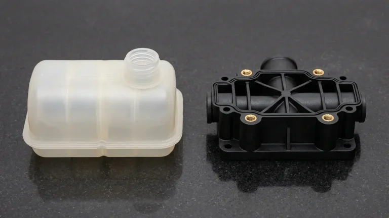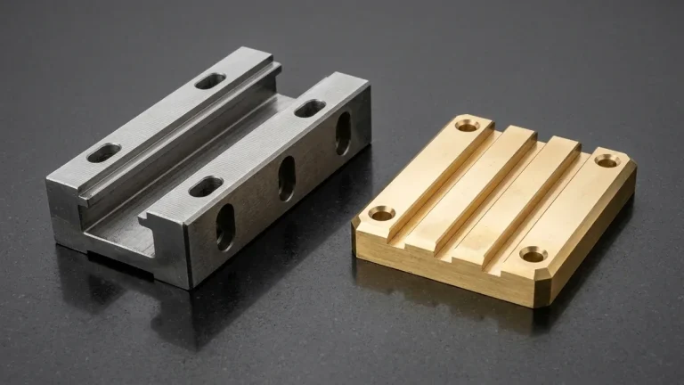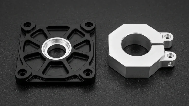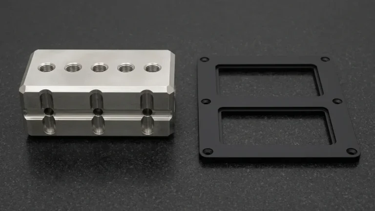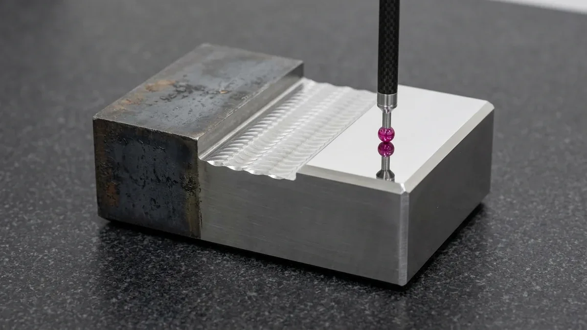
In high-precision CNC manufacturing, the transition from raw stock—whether an extruded billet, continuous cast bar, sand casting, closed-die forging, or 3D printed near-net blank—to a micrometer-accurate finished component is governed by one critical engineering variable: machining allowance (frequently designated as stock allowance, Z). Far from being an arbitrary safety margin, machining allowance represents a strategically engineered envelope of excess material intentionally retained on a workpiece to be progressively removed across controlled machining operations.
For product designers, procurement engineers, and machinists alike, properly budgeting this sacrificial material layer dictates manufacturing success. Allocating excessive allowance inflicts severe financial penalties: inflated raw material volume, prolonged machine cycle times, accelerated cutting tool wear, and excessive cutting heat that triggers part distortion.
Conversely, under-allowancing is fatal to precision parts. Insufficient stock prevents finishing cutters from engaging beyond the minimum uncut chip thickness (hmin), causing tools to burnish, rub, and skate across work-hardened surfaces, inevitably leading to dimensional scrapping and failed surface finish requirements.
At AS Prototypes, with over ten years of specialized precision prototyping and production CNC machining heritage, our engineering team manages stock allowances down to the micron. This comprehensive technical guide analyzes the metallurgical and physical mechanics of machining allowance, details analytical and empirical calculation formulas, provides an alloy-by-alloy benchmark matrix, and demonstrates how to budget stock across roughing, semi-finishing, and micro-finishing operations to reliably hit tolerances down to ±0.01 mm.
- 1. Machining Allowance vs. Engineering Tolerance: Clarifying the Fundamental Distinction
- 2. The Anatomy of Machining Allowance: Step-by-Step Material Allocation
- 3. The Physics of Minimum Chip Thickness (hmin): Why Under-Allowancing Destroys Tooling
- 4. Comprehensive Engineering Benchmark Table: Machining Allowances by Blank Type & Material
- 5. Material-Specific Allowance Dynamics & Engineering Countermeasures
- 6. Advanced CAM Strategies for Machining Allowance Management
- 7. Design for Manufacturability (DFM): Engineering Tips for Optimal Allowances
- 8. Technical Engineering FAQ
1. Machining Allowance vs. Engineering Tolerance: Clarifying the Fundamental Distinction
In mechanical drafting and Design for Manufacturability (DFM) reviews, junior engineers occasionally conflate machining allowance with engineering tolerance. While both govern component geometry, they fulfill opposing functional roles in the production lifecycle:
- Machining Allowance (Z): An intentional, planned thickness of excess material budgeted between operational stages. Total machining allowance (Z0) is the gross difference between the initial blank dimension and the final blueprint dimension. Operational allowance (Zi) is the specific depth of cut removed during a single manufacturing step (e.g., rough turning, semi-finish milling, or cylindrical grinding). It is a process variable determined by manufacturing engineers.
- Engineering Tolerance (T or ±Δ): The unintentional yet permissible limit of physical deviation from the nominal blueprint dimension. Tolerances account for inevitable machine tool inaccuracies, cutter deflection, thermal drift, and fixturing repeatability. Tolerance is a design constraint mandated by the product engineer to guarantee mechanical fit and assembly interchangeability.
Mathematically, the relationship between operational allowance (Zi) and operational tolerance (Ti) dictates that the minimum machining allowance must always absorb the accumulated geometric errors, clamping deviations, and surface defects of the preceding manufacturing step:
Zi,min ≥ Rzi−1 + hi−1 + Δi−1 + εi
Where Rzi-1 is the peak-to-valley roughness of the preceding cut, hi-1 is the depth of the defective surface/work-hardened layer, Δi-1 represents spatial form errors (straightness, parallelism, runout), and εi represents workpiece fixturing and datum location error in the current setup.
2. The Anatomy of Machining Allowance: Step-by-Step Material Allocation
Total machining allowance (Z0) is partitioned into sequential sub-allowances, each engineered to perform a distinct metallurgical and mechanical function:
1. Roughing Allowance (Zrough)
Roughing represents the bulk material removal phase. The primary objective is volumetric efficiency (high Material Removal Rate, MRR). The roughing allowance must be large enough to strip away raw stock surface defects, including:
- Decarburized zones, scale, and micro-cracks on hot-forged blanks;
- Chilled iron/aluminum crusts, sand inclusions, and draft angle tapers on cast blanks;
- Oxidized skins and residual drawing stresses on cold-finished or hot-rolled bar stock.
Roughing operations generate substantial cutting forces (Fc) and thermal spikes. Consequently, roughing passes induce elastic workpiece deflection and machine spindle vibration. A generous residual envelope must be preserved to isolate the finished geometry from these severe roughing perturbations.
2. Semi-Finishing Allowance (Zsemi)
Semi-finishing operations true the workpiece geometry after the violent stress-release of roughing. During roughing of large aluminum or titanium billets, internal residual stresses uncoil, causing the part to warp or bow. The semi-finishing pass removes this geometric distortion, establishing clean, true datum faces and leaving a perfectly uniform residual stock layer (0.3 to 0.6 mm) for the finishing cutters.
3. Finishing Allowance (Zfinish)
The finishing cut establishes final blueprint dimensions, geometric tolerances (GD&T), and surface roughness (Ra). Here, depths of cut typically range between 0.10 mm and 0.30 mm. Cutting parameters prioritize high cutting velocity (vc), light feed per tooth (fz), and minimal tool deflection to prevent dimensional tapering across deep pockets.
4. Super-Finishing / Grinding / Honing Allowance (Zgrind)
For precision bearing journals, hydraulic spool valves, or optical mold cores requiring fine ground finishes (Ra ≤ 0.2 μm) and IT6 to IT7 tolerance grades, conventional milling or turning is followed by grinding, diamond burnishing, or lapping. Grinding allowances are kept intentionally minuscule (0.02 to 0.08 mm) to avoid thermal micro-cracking (grinding burn) and wheel loading.
3. The Physics of Minimum Chip Thickness (hmin): Why Under-Allowancing Destroys Tooling
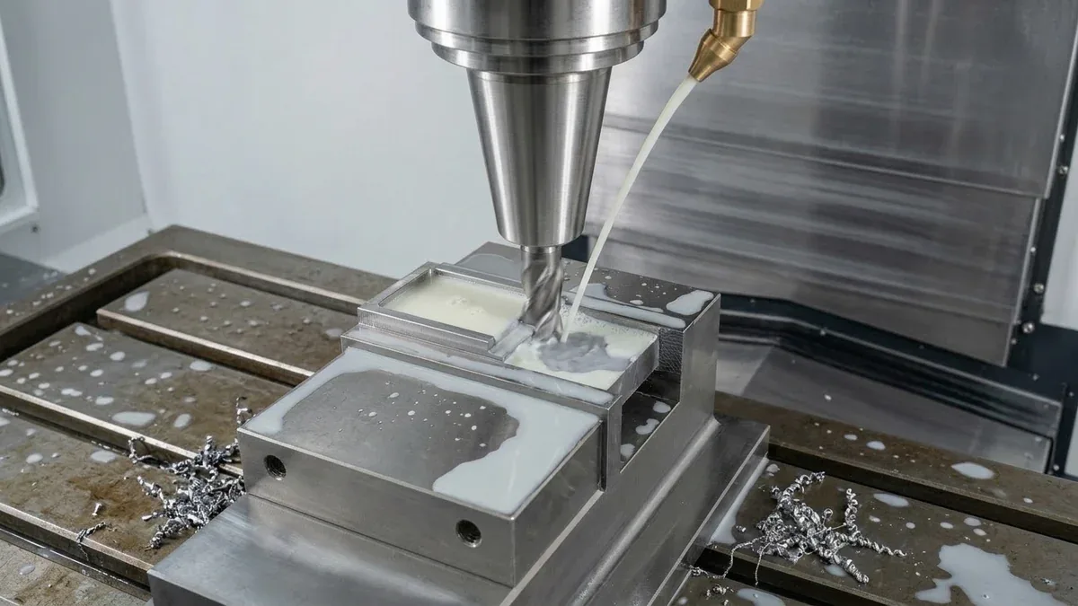
One of the most dangerous misconceptions in machining is the belief that leaving “as little stock as possible” automatically yields superior precision. In physical reality, every cutting tool possesses a finite cutting edge radius (rε, typically 5 to 20 μm for honed carbide, or 2 to 5 μm for mirror-ground micro-grain tools).
Orthogonal metal cutting physics dictates that a chip will only shear cleanly when the uncut chip thickness (h) exceeds a critical material-dependent threshold known as the minimum uncut chip thickness (hmin ≈ 0.1 to 0.3 · rε).
When an engineer leaves an inadequate finishing allowance (e.g., ap < 0.03 mm with a standard honed tool), the cutting edge cannot penetrate the shear zone. Instead of cleanly slicing chips, the tool edge repeatedly compresses, rubs, and burnishes the metal surface. This phenomenon triggers catastrophic process failures:
- Severe Work Hardening: In austenitic stainless steels (AISI 304, 316L), precipitation-hardened steels (17-4PH), and nickel superalloys (Inconel 718), rubbing forces strain-harden the surface layer by up to 200%. The tool tip instantaneously encounters a rock-hard crust, causing micro-chipping, notch wear, and thermal tool burnout within seconds.
- Tool Skating & Dimensional Taper: The intense radial thrust force pushes the cutting tool away from the part (cutter deflection). The tool “skates” across the stock, leaving behind dimensional tapers, out-of-round bores, and barrel-shaped bosses.
- Severe Surface Tearing: Rather than achieving a low Ra mirror finish, burnished surfaces develop micro-tears, orange-peel textures, and residual tensile stresses that degrade the component’s fatigue life.
4. Comprehensive Engineering Benchmark Table: Machining Allowances by Blank Type & Material
The optimal machining allowance varies dramatically depending on the raw material morphology, thermal expansion characteristics, and blank fabrication method. The engineering benchmark table below outlines standardized allowance allocations established across AS Prototypes production runs:
| Blank Type & Material | Raw Blank Tolerance | Total Allowance (Z0) | Roughing (Zrough) | Semi-Finishing (Zsemi) | Finishing (Zfinish) | Critical Process Control Rule |
|---|---|---|---|---|---|---|
| Sand Cast Aluminum / Iron (A356, HT250) | ±1.5 to ±3.0 mm | 3.5 – 6.0 mm | 2.5 – 4.5 mm | 0.6 – 1.0 mm | 0.2 – 0.4 mm | Initial roughing cut depth must penetrate below sand inclusions and abrasive chilled surface skin. |
| Precision Die Cast Aluminum (A380, ADC12) | ±0.2 to ±0.5 mm | 1.0 – 2.0 mm | 0.8 – 1.4 mm | N/A or 0.3 mm | 0.15 – 0.25 mm | Avoid deep cuts that breach the dense chill layer into subsurface porosity zones. |
| Closed-Die Forged Steel (4140, 1045) | ±0.8 to ±1.5 mm | 2.0 – 4.0 mm | 1.5 – 2.8 mm | 0.4 – 0.7 mm | 0.15 – 0.3 mm | First pass must completely clear forging flash parting lines and decarburized oxide scales. |
| Extruded Billet Aluminum (6061-T6, 7075-T651) | ±0.3 to ±0.8 mm | 1.5 – 3.0 mm | 1.0 – 2.2 mm | 0.3 – 0.5 mm | 0.10 – 0.20 mm | Execute symmetrical roughing to balance internal stress relief; rest part prior to finishing. |
| Stainless Steel Bar Stock (304, 316L) | h9 to h11 (0.1 mm) | 1.0 – 2.5 mm | 0.7 – 1.8 mm | 0.3 – 0.4 mm | 0.15 – 0.25 mm | Finishing allowance must remain >0.15 mm to prevent tool burnishing against work-hardened zones. |
| Aerospace Titanium Billet (Ti-6Al-4V Grade 5) | ±0.2 to ±0.5 mm | 1.5 – 3.0 mm | 1.0 – 2.0 mm | 0.3 – 0.5 mm | 0.20 – 0.35 mm | Low modulus requires high finish allowance to overcome workpiece springback under tool pressure. |
| Engineering Thermoplastic (POM-C / Delrin) | ±0.4 to ±1.0 mm | 1.5 – 3.0 mm | 1.0 – 2.0 mm | 0.4 – 0.6 mm | 0.20 – 0.40 mm | Single-flute polished diamond/carbide tools required; light cuts prevent thermal softening and tear-out. |
5. Material-Specific Allowance Dynamics & Engineering Countermeasures
1. Aerospace Aluminum Alloys (6061-T6, 7075-T651)
While aluminum boasts superior machinability (kc ≈ 800 N/mm2), it exhibits a high coefficient of thermal expansion (α ≈ 23 × 10-6/K) and substantial locked-in residual stress profiles, particularly in thick rolled plates. During aggressive roughing of thin-walled aerospace structural brackets or pocketed optical enclosures, redistributing internal stresses causes instantaneous bowing (“oil-canning”).
The AS Prototypes Protocol: We implement multi-stage symmetrical roughing. Instead of roughing one side down to final finish stock, we rough Side A to +1.5 mm, flip the component to rough Side B to +1.5 mm, and allow the part to thermally stabilize at 20°C in our metrology lab. Semi-finishing then trims the stock to +0.3 mm, followed by final high-speed finishing with balanced climb milling, ensuring flatness within 0.01 mm across 300 mm spans.
2. Titanium Alloys (Ti-6Al-4V Grade 5)
Titanium presents dual metallurgical challenges: an extremely low thermal conductivity (k ≈ 6.7 W/m · K, roughly 1/25th of aluminum) and a low elastic modulus (E ≈ 110 GPa). The low elastic modulus means that under cutting pressure, the workpiece deflects elastically away from the cutter and violently springs back behind the tool tip.
The AS Prototypes Protocol: If the finishing allowance is set too small (< 0.15 mm), the deflected titanium workpiece merely rubs against the flank face, rapidly inducing tool wear and catastrophic chatter. We program a rigid finishing allowance between 0.25 mm and 0.35 mm paired with positive rake, sharp PVD AlTiN-coated carbide tooling and high-pressure through-spindle coolant (70 bar) to ensure continuous, vibration-free shearing.
3. Austenitic & Precipitation-Hardening Stainless Steels (316L, 17-4PH)
Austenitic stainless steels are infamous for rapid work-hardening. During roughing cuts, plastic deformation beneath the shear plane creates a strain-hardened layer that can reach depths of 0.05 to 0.10 mm.
The AS Prototypes Protocol: If the subsequent semi-finishing or finishing allowance is budgeted within this strain-hardened depth, the cutter teeth will impact work-hardened material on every revolution. We enforce a strict rule: finishing allowance on austenitic stainless steel must never be less than 0.18 mm. This ensures the cutting edge cuts underneath the strain-hardened crust into pristine parent metallurgy.
6. Advanced CAM Strategies for Machining Allowance Management
Modern CAM programming bridges the gap between theoretical stock allowances and actual shop-floor execution. At AS Prototypes, our multi-axis CAM programmers utilize specialized strategies to maintain immaculate stock envelopes:
1. Dynamic / Trochoidal Adaptive Roughing
Traditional offset pocketing roughs parts by driving cutters directly into internal 90° corners. When a cutter enters a corner, its radial engagement angle spikes from 30° to 180°, causing instantaneous cutter deflection and leaving heavy, non-uniform stock scallops (cusps). Modern dynamic toolpaths (VoluMill, Mastercam Dynamic Motion) maintain a constant tool engagement angle and chip load. This guarantees an exceptionally uniform residual stock envelope across straight walls and tight radii alike, eliminating chatter during subsequent finishing passes.
2. Rest Machining (Remaining Stock Clearance)
When transitioning from large-diameter roughing endmills (e.g., Ø 16 mm) to small-diameter finishing endmills (e.g., Ø 3 mm for tight internal fillet radii), localized stock corners retain massive triangles of excess material. Plunging a finishing cutter directly into these heavy stock concentrations causes immediate tool breakage. CAM rest machining cycles automatically identify remaining stock volumes and deploy intermediate semi-finishing endmills (Ø 8 mm → Ø 5 mm) to step-down the stock uniformly before final finishing.
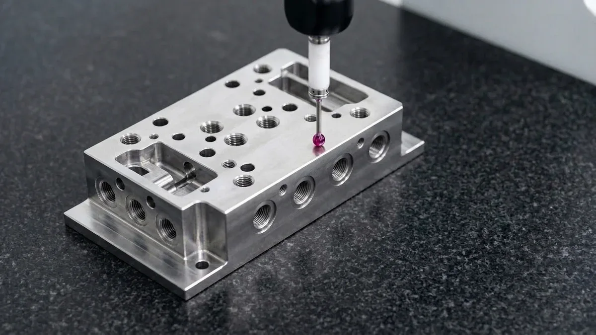
3. In-Process Touch Probing & Adaptive WCS Update
On high-value large castings, weldments, or aerospace forgings, raw blank geometric variations often exceed ±2.0 mm. Clamping such blanks without stock verification risks “air-cutting” on one side and catastrophic tool overload on the opposite side.
AS Prototypes equips its high-speed 3-axis, 4-axis, and 5-axis machining centers with Renishaw optical surface probes. The probe automatically measures the blank’s true spatial boundaries, best-fits the CAD model within the actual material envelope, and updates the Work Coordinate System (WCS) offsets to distribute machining allowances symmetrically across all critical faces.
7. Design for Manufacturability (DFM): Engineering Tips for Optimal Allowances
Design engineers can dramatically optimize manufacturing lead times and part costs by incorporating allowance-conscious DFM guidelines into initial 3D models:
- Standardize Raw Stock Sizes: Designing a shaft with an outer diameter of Ø 50.2 mm forces the machine shop to source expensive Ø 60 mm bar stock, requiring an enormous 9.8 mm total machining allowance. Adjusting the nominal design to Ø 48.0 mm allows procurement of standard Ø 50.0 mm cold-drawn stock with an optimal 2.0 mm total allowance, cutting raw material costs by 35% and machining time by 50%.
- Provide Generous Draft Angles on Near-Net Castings: Ensure casting features incorporate consistent draft (1.5° to 3.0°). Variable draft forces machinists to increase roughing allowances to avoid leaving unmachined casting skin on deep walls.
- Avoid Unnecessary Super-Finishing Callouts: Specifying an ultra-fine surface finish (Ra ≤ 0.4 μm) across non-critical clearance faces forces the addition of semi-finishing and grinding cycles with micro-allowances. Restrict tight finishes to critical bearing seats, sealing surfaces, and optical datum faces.
8. Technical Engineering FAQ
For general precision milling of aluminum 6061-T6, the standard finishing allowance is 0.15 to 0.25 mm on walls and 0.10 to 0.15 mm on floors. On micro-precision components requiring tolerances within ±0.01 mm, a semi-finishing pass leaves 0.10 mm, followed by a final spring pass of 0.05 mm using sharp, polished uncoated carbide tooling.
Leaving too small an allowance (< 0.10 mm) causes the cutting edge to engage within the work-hardened zone produced during roughing. Furthermore, the depth of cut falls below the minimum uncut chip thickness (hmin), causing the tool to rub and burnish rather than shear. This results in severe chatter, rapid tool wear, and a torn, irregular surface texture.
Raw blank fabrication dictates dimensional repeatability and surface condition. Sand castings have wide dimensional variances (±2 mm) and abrasive chilled skins, requiring total allowances of 3.5 to 6.0 mm. Conversely, precision cold-drawn bar stock or extruded billets have high dimensional consistency, requiring only 1.0 to 2.5 mm total allowance.
Partner with Our Precision CNC Machining & Engineering Team
Eliminate tool deflection, residual stress distortion, and tolerance stack-up risks before production begins. Upload your 3D CAD files (STEP/IGES) and 2D GD&T drawings for a comprehensive shop-floor DFM review and custom quotation.
Upload 3D CAD for Engineering DFM & RFQ