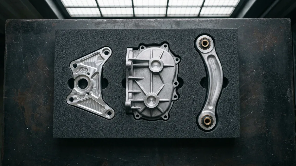
Mastering billet vs cast vs forged aluminum is essential for hardware teams balancing tight dimensional tolerances, surface integrity, and scalable production economics. In structural hardware development, aluminum is the predominant lightweight alloy across aerospace, motorsport, robotics, and consumer electronics. However, specifying “aluminum” on an engineering drawing is fundamentally incomplete without designating the metallurgical manufacturing method: billet, cast, or forged.
Although two components may share identical CAD geometries and nominal chemical designations (such as Al-Si-Mg or Al-Zn-Mg-Cu systems), their raw forming route dictates their internal grain flow, porosity levels, directional fatigue resistance, and post-machining anodizing response. At AS Prototypes, our manufacturing engineers guide hardware teams through the technical tradeoffs of billet vs cast vs forged aluminum to deliver components that satisfy structural loads and maintain tight ±0.010 mm (±0.0004″) dimensional tolerances.
Executive Summary & Engineering Takeaways (BLUF)
- Microstructure & Porosity Contrast: Wrought billet aluminum (6061-T651, 7075-T651) features a dense, rolled/extruded laminar grain with zero internal porosity; cast aluminum (A380, A356-T6) has an isotropic dendritic structure prone to 0.5%–2% gas/shrinkage micro-porosity; forged aluminum (6082-T6, 7075-T6) aligns continuous grain flow along 3D part contours.
- Fatigue & Tensile Hierarchy: Forged 7075-T6 achieves the highest high-cycle fatigue endurance (160–190 MPa at 107 cycles) and impact toughness, wrought 7075-T651 billet delivers 572 MPa (83.0 ksi) tensile strength with zero die NRE, and die-cast A380 provides ~310 MPa (45.0 ksi) tensile strength for thin-wall mass production.
- Anodizing & Cosmetic Clarity: Wrought 6061/7075 billet (<0.8% Si) and 6061/6082 forgings (0.4%–1.3% Si) produce vibrant, uniform MIL-A-8625 Type II clear and dyed anodic coatings; cast aluminum alloys (A356, A380, ADC12) contain 7.0%–12.0% silicon for melt fluidity, which turns dark mottled gray during anodizing.
- Volume Crossover Economics: Direct CNC machining from billet stock dominates 1 to 2,500+ units (zero tooling NRE, 4–8 business days turnaround); high-pressure die casting plus CNC post-machining wins above 5,000+ units; closed-die forging plus CNC finishing serves safety-critical suspension and aerospace links above 1,000+ units.
Article Engineering Navigation
- 1. What is Billet Aluminum? (Wrought Extruded & Rolled)
- 2. What is Cast Aluminum? (High-Pressure Die & Sand Casting)
- 3. What is Forged Aluminum? (High-Pressure Compressive Deformation)
- 4. Engineering Comparison Matrix: Billet vs Cast vs Forged Aluminum
- 5. How to Select the Ideal Aluminum Process for Your Project
- 6. Quantitative Grain-Flow Strengthening, Fatigue Life & NRE Break-Even Equations
- 7. Technical Engineering FAQ
1. What is Billet Aluminum? (Wrought Extruded & Rolled)
In precision manufacturing, billet aluminum refers to solid wrought stock produced by continuous casting followed by hot rolling or extrusion into dense bars, plates, or square billets. Common wrought alloys include 6061-T6, 7075-T651, and 2024-T351.
Because billet stock is heavily hot-worked during extrusion and subsequently solution heat-treated, it possesses a homogeneous, dense crystalline microstructure devoid of gas voids or shrinkage cavities. Billet aluminum is the cornerstone of precision CNC machining, enabling engineers to machine complex structural cavities, thin-walled aerospace housings, and high-tolerance fluidic blocks directly from solid stock without investing in upfront tooling or dies.
Key Advantages of Billet Aluminum:
- Zero Tooling Investment (NRE): Billet parts require no physical molds or forging dies, enabling 4-to-8-business-day ex-factory turnaround for rapid prototyping and agile engineering revisions.
- Flawless Microstructural Density: Freedom from internal gas porosity guarantees hermetic sealing in high-pressure pneumatic, hydraulic, and vacuum applications.
- Superior Anodizing Quality: Low silicon content (<0.8%) allows billet alloys like 6061 and 6082 to accept brilliant, uniform Type II color anodizing and high-dielectric Type III hardcoating.
- Exceptional Dimensional Stability: When using pre-stretched temper grades (such as T651), internal stresses are mechanically relieved, preventing warping during deep pocket milling.
2. What is Cast Aluminum? (High-Pressure Die & Sand Casting)
Cast aluminum is manufactured by liquefying aluminum ingots above 660°C and injecting or pouring the molten metal into a mold cavity. Common casting alloys include A380, A383, ADC12 (die casting), and A356 (sand/investment casting).
To ensure high fluidity and prevent premature solidification in intricate mold thin walls, casting alloys incorporate high concentrations of Silicon (8.5% to 12% Si) and Copper. While casting represents the most cost-effective solution for producing tens of thousands of complex housings (such as automotive transmission cases and power tool shells), it introduces significant engineering compromises:
- Entrained Porosity and Shrinkage Voids: High-velocity injection entraps gas and causes micro-porosity during cooling. When a CNC tool breaches the outer casting skin to machine seal grooves or bearing bores, exposed sub-surface voids can cause pressure leaks.
- Lower Ductility and Impact Resistance: The presence of coarse silicon needles and eutectic phases creates micro-stress concentrations, resulting in low elongation (typically 1% to 3.5%) compared to wrought alloys (>10%).
- Severe Anodizing Limitations: The heavy silicon content does not dissolve in sulfuric acid anodizing baths. Anodizing standard die cast alloys yields a splotchy, dull dark-grey or black finish, making decorative color anodizing impractical without specialized, high-cost masking or plating.
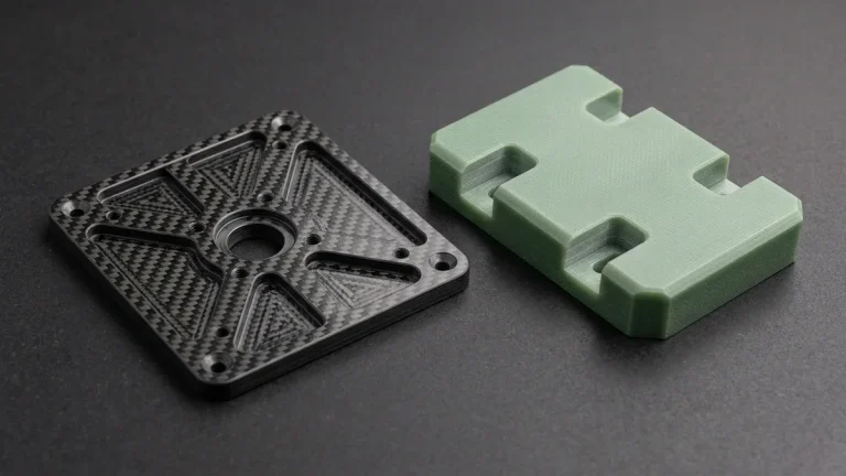
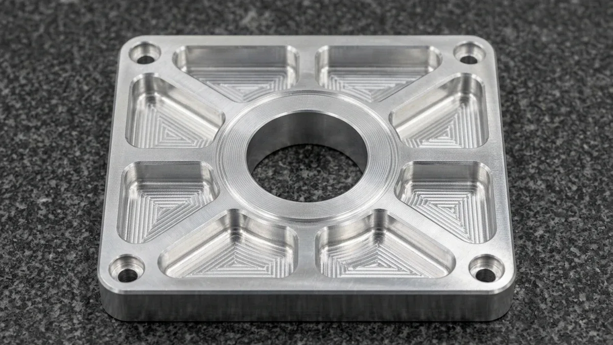
As illustrated in Figure 1, a monolithic 7075-T651 wrought billet aluminum structural actuator frame rests flat on black granite, showcasing deep triangular weight-relief pockets and thin intersecting stiffening ribs CNC-milled directly from solid plate stock. Wrought billet eliminates internal casting porosity across high-stress load paths.
3. What is Forged Aluminum? (High-Pressure Compressive Deformation)
Forged aluminum is produced by taking heated solid billet stock and plastically deforming it between heavy mechanical dies under thousands of tons of hydraulic pressure. Common forging alloys include 6082-T6, 7050-T7452, and 2618 (high-temperature piston alloy).
Forging forces the metal to flow along the contours of the finished part geometry. This continuous, unbroken grain flow aligns along critical principal stress vectors, yielding the highest fatigue life, fracture toughness, and impact resistance of any aluminum manufacturing method.
Key Advantages of Forged Aluminum:
- Continuous Directional Grain Flow: Compressive mechanical working refines grain boundaries, eliminating directional weak planes and preventing stress corrosion cracking under dynamic cyclic fatigue.
- Ultimate Structural Integrity: Forged alloys (e.g., 7050 or 7075 forgings) achieve tensile strengths exceeding 550 MPa (80 ksi) with outstanding elongation, making them mandatory for aerospace landing gear, aircraft bulkheads, and racecar uprights.
- High Density Without Voids: Extreme forging tonnage completely crushes any residual microscopic voids, ensuring 100% volumetric solid density.
4. Engineering Comparison Matrix: Billet vs Cast vs Forged Aluminum
To guide material selection for production and prototyping, the following table compares the mechanical, metallurgical, and economic attributes of each aluminum category:
| Engineering Property | Billet Aluminum (6061-T6 / 7075-T6) | Cast Aluminum (A380 / ADC12) | Forged Aluminum (6082 / 7050) |
|---|---|---|---|
| Microstructural Grain Flow | Linear, uniform longitudinal grain | Random dendritic, non-directional | Continuous contoured grain flow |
| Tensile Strength (Yield / Ultimate) | 276 / 310 MPa (6061-T6) 503 / 572 MPa (7075-T6) | 160 / 320 MPa (A380) Low yield-to-tensile ratio | 310 / 350 MPa (6082-T6) 490 / 550 MPa (7050-T74) |
| Internal Porosity & Leak Risk | Zero porosity (100% solid wrought) | Moderate to High (requires vacuum impregnation) | Zero porosity (fully consolidated under pressure) |
| CNC Machinability & Tolerance | Outstanding (±0.01mm repeatable) | Fair (silicon causes abrasive tool wear) | Good (requires rigid tooling setups) |
| Anodizing Surface Quality | Flawless Type II color & Type III hardcoat | Poor (turns dark grey/mottled; powder coat preferred) | Excellent (dense surface accepts vibrant dyes) |
| Tooling Cost (NRE) & Lead Time | Zero dedicated mold tooling; 4 – 8 business days ex-factory turnaround | Moderate dedicated die investment; 18 – 35 business days tooling & T1 turnaround | High closed-die forging tooling investment; 25 – 45 business days tooling turnaround |
| Optimal Production Volume | 1 to 5,000 units (Prototypes to Low-Volume) | > 5,000 units (Mass Production) | > 1,000 units (Safety-Critical Components) |
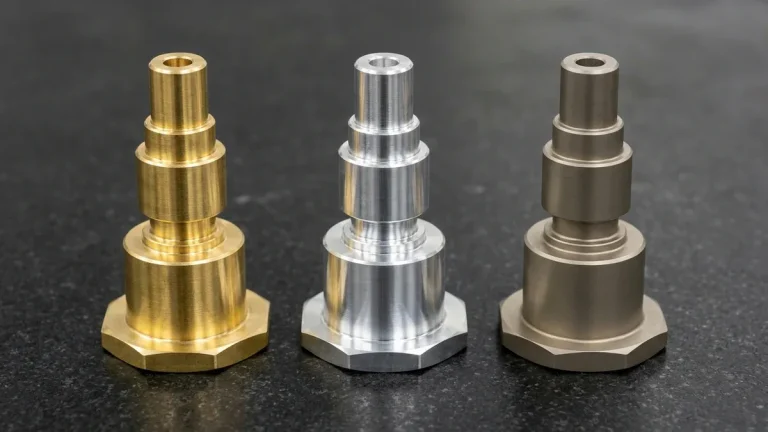
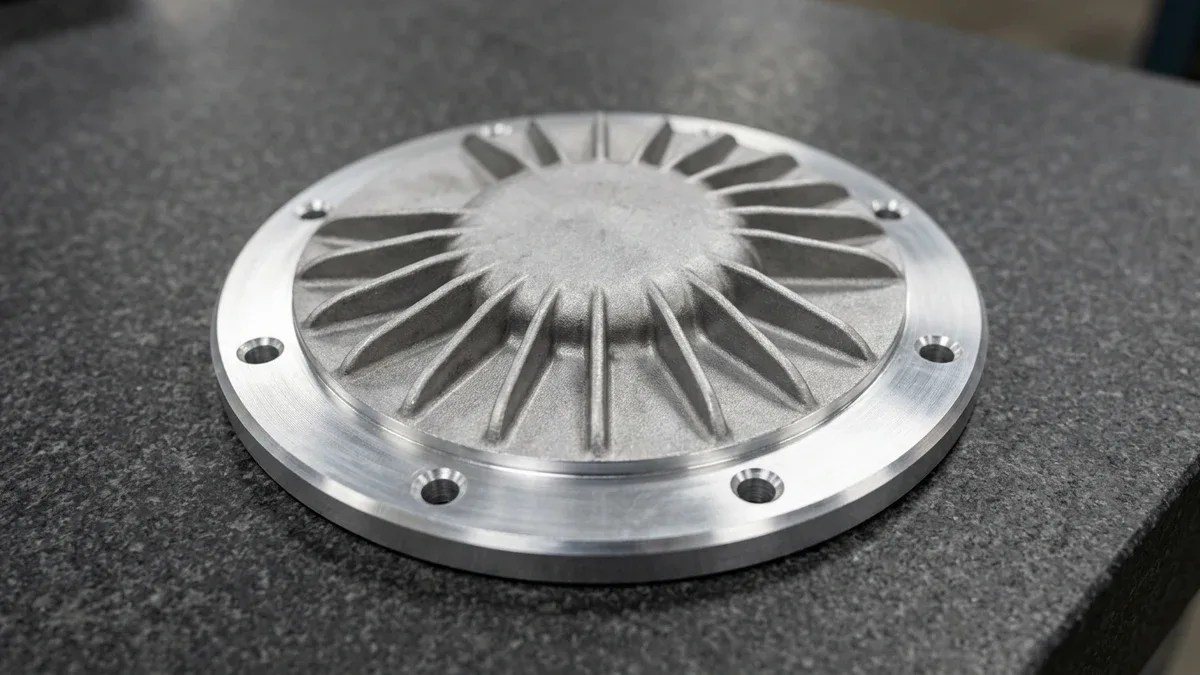
For medium-to-high production volumes, Figure 2 shows a post-machined A356-T6 cast aluminum hydraulic pump cover resting flat on granite, contrasting its matte textured as-cast radial cooling fins against a bright CNC face-milled perimeter sealing flange. Limiting finish stock removal to 0.5–0.8 mm preserves the dense chilled casting skin.
5. How to Select the Ideal Aluminum Process for Your Project
Navigating the choice between billet, cast, and forged aluminum requires balancing mechanical fatigue requirements, cosmetic surface expectations, and total project lifecycle economics:
- Choose Billet Aluminum for Rapid Prototyping & Precision Assemblies: When part geometries require intricate multi-axis features, sub-ten-micron tolerances, hermetic pressure sealing, or premium cosmetic anodizing and surface finishes, billet CNC machining is the definitive choice. It eliminates tooling delays and allows continuous iterative optimization.
- Choose Cast Aluminum for High-Volume Thin-Walled Enclosures: When scaling production beyond 10,000 units annually where structural fatigue loads are minimal and unit price must be minimized (e.g., electronic junction boxes, automotive brackets, and pump volutes), high-pressure die casting provides the lowest per-part cost despite upfront tooling expenses.
- Choose Forged Aluminum for Severe Dynamic Fatigue & Impact: When parts are subjected to intense cyclic shock, continuous reversing stresses, or flight-critical safety documentation (such as aircraft landing gear, motorsport suspension knuckles, and forged wheels), closed-die forging delivers unmatched fatigue life and fracture resistance.
6. Quantitative Grain-Flow Strengthening, Fatigue Life & NRE Break-Even Equations
Hall-Petch Grain Refinement and Basquin High-Cycle Fatigue Mechanics
The mechanical performance gap between die-cast aluminum (A380 / A356), wrought CNC billet (6061-T651 / 7075-T651), and closed-die forged aluminum (6082-T6 / 7050-T74) is rooted in dislocation physics. Under the Hall-Petch relationship, severe compressive plastic deformation during rolling, extrusion, and forging breaks coarse cast dendrites (dg ≈ 80–200 μm) down into fine, elongated wrought grains (dg ≈ 10–35 μm) while closing 100% of internal shrinkage voids.
• Hall-Petch Yield Strength Scaling: σy = σ0 + ky × dgrain−1/2 [MPa] (where dgrain = average grain diameter)
• Basquin High-Cycle Fatigue Law: σa = (σ′f / Kf) × (2 × Nf)b (Forged continuous grain lowers fatigue notch factor Kf)
• Tooling NRE Break-Even Volume: Qcrossover = NREdie_tooling / (Cunit,billet_CNC − Cunit,cast_or_forged) [units]
Why End-Grain Exposure in Billet-Hogged Brackets Reduces Fatigue Endurance
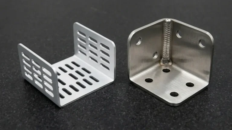
When an L-shaped or U-shaped suspension clevis is hogged out of a flat rolled 7075-T651 billet plate, the CNC end mill cuts perpendicularly across the unidirectional longitudinal (L) rolling fibers at the 90° transition fillet. Under cyclic bending loads, exposed short-transverse (ST) grain boundaries at the fillet surface experience 15%–25% lower fatigue endurance than a closed-die forging where metallurgical grain flow wraps continuously around the corner contour.
| Observed Defect / Symptom | Physical Root Cause | Quantitative Process Threshold | Corrective Shop-Floor Action | Inspection Verification Method |
|---|---|---|---|---|
| Pneumatic / hydraulic pressure leak after machining cast housing | CNC cutter milling past dense 0.8 mm chilled die-cast skin into porous core | Machining stock removal > 1.0 mm on A380 / ADC12 high-pressure die casting | Restrict post-cast CNC skim allowance to 0.4–0.8 mm, perform methacrylate vacuum impregnation, or switch to wrought 6061-T651 billet | Helium mass-spectrometer leak test or 6 bar underwater bubble decay test |
| Mottled dark gray smudge after MIL-A-8625 Type II anodizing | High eutectic Silicon (7.0%–12.0% Si) in cast A356/A380/ADC12 insoluble in sulfuric acid | Alloy silicon content > 1.5% preventing clear transparent Al2O3 growth | Specify wrought 6061-T651 billet (< 0.8% Si) or 6061-T6 / 6082-T6 forging (0.4%–1.3% Si) for cosmetic anodizing; use powder coating or e-coat on castings | Optical colorimeter ΔE check and eddy-current anodic film thickness gauge |
| Stress-corrosion or fatigue cracking at billet clevis root | Peak tensile load aligned parallel to weak Short-Transverse (ST) plate thickness axis | Sustained tensile stress > 45% yield across ST grain in 7075-T6 | Re-orient blank in L-LT plane, switch to over-aged 7075-T7351 / 7050-T7451 temper, or transition to closed-die forging | Metallographic grain-flow macro-etch (ASTM E340) and dye penetrant NDT |
| Wall thickness shift when finish-machining forged or cast blanks | Die closure mismatch or thermal warp shifting raw near-net contour relative to vise | Forging/casting raw profile tolerance ±0.5 to ±1.2 mm exceeding fixed vise stops | Establish 3-2-1 cast/forged datum targets on un-machined bosses and use in-spindle Renishaw probing to align WCS per part | Zeiss CMM 3D best-fit alignment scan and ultrasonic wall thickness check |
Four-Step DFM Protocol for Selecting Billet vs. Cast vs. Forged Aluminum
- Calculate Buy-to-Fly Ratio vs. Annual Batch Volume: Keep parts with < 1,500 unit annual volume or tight geometric revision schedules on zero-tooling 6061-T651 / 7075-T651 billet CNC machining.
- Prototype Future Castings in Billet With Castable DFM Rules Built In: Machine EVT/DVT prototypes from 6061-T651 billet using 2.5 mm uniform walls and 1.5° draft angles so the exact same CAD geometry transitions into an A380 die-cast tool at PVT without re-testing.
- Keep Post-Casting CNC Skim Allowances Between 0.4 mm and 0.8 mm: Never machine deep pockets into high-pressure die castings; core the pocket inside the die steel so the CNC cutter only skims the dense outer skin.
- Align Primary Tensile Loads With the Longitudinal (L) Grain Direction: On high-load aerospace or motorsport billet brackets, add a 2D drawing note specifying grain direction parallel to the principal stress vector.
🔗 Related Aluminum Alloys, Die Casting & CNC Machining Guides
7. Technical Engineering FAQ
Cast alloys like A356, A380, and ADC12 contain 7.0%–12.0% silicon that remains trapped in the MIL-A-8625 oxide layer, scattering light as a mottled gray smudge. For uniform cosmetic dyeing, specify wrought 6061-T6 billet (0.4%–0.8% Si) or apply powder coating on castings.
Yes, secondary CNC milling and turning on A356-T6 or A380 castings routinely hold ±0.010–0.020 mm tolerances across critical bearing bores, sealing flanges, and threaded ports. Keep die-cast machining stock between 0.4–0.8 mm so cutters stay within the dense chilled skin without exposing internal porosity.
Closed-die forging boosts cyclic fatigue strength by 15%–25% over machined billet because plastic deformation forces metallurgical grain flow to follow the part contour continuously. Conversely, milling curved brackets from rectangular billet slices across unidirectional rolling grains, leaving exposed end-grains at fillets where cracks initiate.
For 1–200 EVT/DVT units, CNC machining from 6061-T651 or 7075-T651 billet validates structural and thermal performance in 4–8 business days without tooling investment. Model future 1.5° draft angles, 2.5 mm uniform walls, and fillets into the CAD geometry before authorizing 18–35 day die fabrication.
Ready to Validate Your CAD Design for Precision Manufacturing?
Upload your 3D CAD models (STEP, IGES, SolidWorks) and 2D engineering drawings for a comprehensive DFM engineering review and custom quotation from our in-house CNC machining and prototyping team.
Request a Custom DFM Review & Quote →