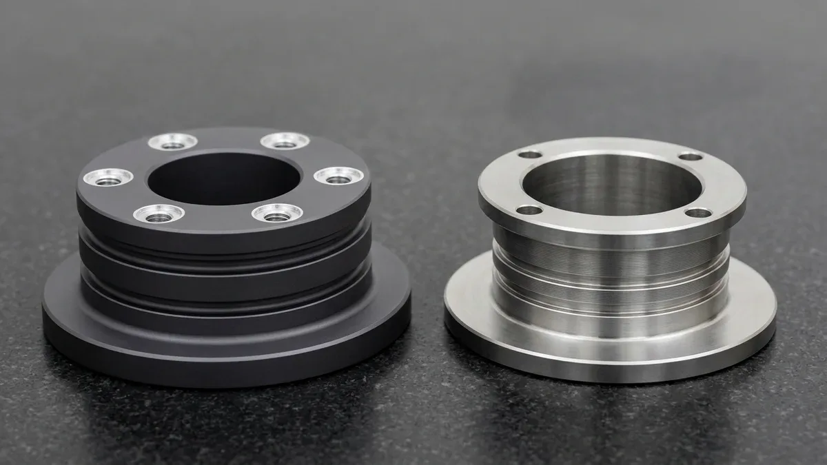
Underwater ROV Design for a remotely operated vehicle (ROV) demands tight integration between hydrostatic pressure-vessel mechanics, Computer Numerical Control (CNC) machining tolerances, and marine corrosion engineering so subsea hulls survive 100 m (328 ft) to 3,000+ m (9,842+ ft) ocean depths. A 0.025 mm (0.0010″) bore ovality error will flood mission-critical avionics bays.
Executive Summary & Engineering Takeaways (BLUF)
- Hydrostatic Hull & Bore Geometry: Machine cylindrical ROV pressure housings with H7 (+0/+IT7) end-cap sealing bores, cylindricity ⌭ 0.010 mm (0.0004″), and coaxiality ◎ 0.015 mm (0.0006″) on turn-mill centers while maintaining general unnoted tolerances per ISO 2768-mK.
- Depth-Matched Alloy Selection: Specify 6061-T651 aluminum with 50 µm (0.0020″) MIL-A-8625 Type III hard anodizing (450–550 HV0.05) for 0–600 m (0–1,968 ft) housings, ASTM A967 passivated 316L for corrosion-critical hardware, and Ti-6Al-4V (Grade 5) for 1,000–6,000 m (3,280–19,685 ft) deep-sea hulls.
- Dual AS568 O-Ring Gland Architecture: Combine dual radial piston seals (15%–25% squeeze, 65%–85% groove fill) with a secondary axial face seal, a burr-free 15°–20° entry chamfer, and a concentric lathe-turned groove finish of Ra 0.4–0.8 µm (16–32 µin).
- Optical Viewports, Leak Testing & Lead Times: Anneal cell-cast PMMA domes at 70–80°C (158–176°F) before diamond turning or SPI A-1 buffing (never flame or DCM vapor polish), validate sealed assemblies via in-house 3.5–6.0 bar (50.8–87.0 psi) pneumatic pressure-decay testing, and expect 7 ~ 12 Business Days ex-factory turnaround for finished prototypes.
Article Engineering Navigation
- 1. Subsea Pressure Hull Mechanics & Quantitative Derivation
- 2. Marine Alloy & Polymer Selection (6061, 7075, 316L, Ti-6Al-4V, PEEK)
- 3. Dual Radial-and-Axial AS568 O-Ring Bulkhead Glands
- 4. 5-Axis CNC Thruster Impellers & Diamond-Turned PMMA Domes
- 5. Galvanic Isolation, Type III Hardcoat & Pressure-Decay Testing
- 6. DFM Checklist, Anti-Selection Traps & Ex-Factory Lead Times
- 7. Technical Engineering FAQ
1. Subsea Pressure Hull Mechanics: How Do Depth Ratings Govern Cylindrical Wall Thickness & Buckling Resistance?
External hydrostatic pressure rises by 0.1005 MPa (1.005 bar / 14.58 psi) per 10 m (32.8 ft) of seawater descent, driving subsea ROV housings to fail via elastic shell buckling or compressive yield rather than tensile burst.
Cylindrical and spherical geometries dominate precision CNC machining for underwater robotic vehicles because curved shells convert external hydrostatic loads into uniform membrane hoop and axial compression. Flat-sided rectangular enclosures experience severe plate-bending stresses at mid-span, requiring 2.8× to 4.2× heavier walls that destroy vehicle buoyancy budgets.
Elastic Shell Instability vs. Material Yield Collapse
In short, thick-walled cylinders (where unsupported tube length-to-diameter ratio L ÷ Do ≤ 2.5 and wall ratio t ÷ Do ≥ 0.08), collapse is governed by circumferential hoop yield stress. However, in elongated ROV electronics tubes (L ÷ Do between 3.0 and 6.0), two-lobe elastic instability occurs well below the alloy yield point.
On our shop floor, thin-to-medium wall cylindrical pressure tubes require strict wall-thickness uniformity and bore roundness to prevent premature asymmetric lobe buckling. If multi-setup clamping leaves a 0.15 mm (0.0059″) wall eccentricity across a cylindrical hull, local bending moments reduce the critical collapse pressure by up to 18%.
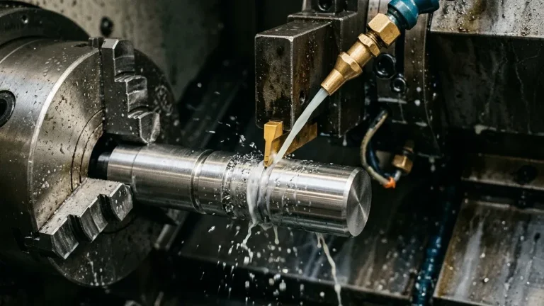
To prevent clamping distortion and wall eccentricity on bored subsea tubes, we rough-turn and bore extruded or forged bar stock on CNC turning centers using wrap-around pie jaws at reduced chuck pressure. For detailed stress-relief cycles and 0.5 mm (0.020″) rough-to-finish stock allowances, review our aluminum CNC milling stress and deformation guide.
Boundary Conditions: Operating depth h = 300 m (984 ft) in seawater (ρ = 1,025 kg/m³, g = 9.80665 m/s², Patm = 101,325 Pa); 6061-T651 cylinder (yield 276 MPa / 40.0 ksi) with outer diameter Do = 120.0 mm (4.724″), bore Ø108 H7 (+0/+0.035 mm), and wall t = 6.0 mm (0.236″).
Step 1 — External Hydrostatic Pressure (P):
Absolute pressure Pabs = ρ × g × h + Patm = (1,025 × 9.80665 × 300) + 101,325 = 3,015,545 + 101,325 = 3,116,870 Pa ≈ 3.117 MPa (31.17 bar / 452.1 psi); across a 1-atm sealed pod, net gauge ΔP = 3.016 MPa (30.16 bar / 437.4 psi).
Step 2 — Hoop Stress & Yield Safety Factor:
Hoop stress σh = (ΔP × Do) ÷ (2 × t) = (3.016 × 120.0) ÷ (2 × 6.0) = 30.16 MPa (4.37 ksi), axial stress σa = 15.08 MPa (2.19 ksi), and yield safety factor SF = 276 ÷ 30.16 = 9.15 (8.85 under Pabs).
Step 3 — AS568-242 Radial Piston O-Ring Diametral Squeeze:
Pairing an AS568-242 O-ring (cross-section W = 3.53 ± 0.10 mm / 0.139″) with a turned bulkhead gland depth Gd = 2.82 mm (0.1110″) yields Squeeze = [(3.53 − 2.82) ÷ 3.53] × 100 = 20.1% (within the 15%–25% static window).
Step 4 — Gland Cross-Sectional Groove Fill Ratio:
Turning groove width Gw = 4.80 mm (0.1890″) gives gland area 2.82 × 4.80 = 13.536 mm² against O-ring area π × (3.53 ÷ 2)² = 9.787 mm², yielding Fill = (9.787 ÷ 13.536) × 100 = 72.3% (inside the 65%–85% limit).
Internal Ring Stiffeners & Datum Alignment
When an ROV battery housing exceeds an unsupported length-to-diameter ratio of 4.0, machining integral internal circumferential stiffening ribs raises elastic buckling collapse resistance by 2× to 3× while adding 30%–40% less mass than thickening the entire cylinder wall.
To prevent boring-bar deflection on deep pressure tubes where internal bore depth exceeds 4× to 6× bar diameter, we utilize tuned carbide-shank anti-vibration boring bars and double-ended rough/finish line boring with tailstock steady-rest support. This holds end-to-end bore coaxiality within ◎ 0.015 mm (0.0006″).
When specifying pressure housing drawings, general non-mating features follow ISO 2768-mK, whereas internal O-ring receiver bores at both ends must be explicitly dimensioned to H7 (+0/+IT7) unilateral limits—such as Ø108 H7 (+0/+0.035 mm, +0/+0.0014″)—paired with cylindricity ⌭ 0.010 mm (0.0004″) and bulkhead shoulder perpendicularity ⊥ 0.015 mm (0.0006″).
2. Material Selection for Marine Corrosion & High-Depth Service: 6061-T651, 7075-T651, 316L Stainless, Ti-6Al-4V & PEEK/HDPE
Selecting corrosion-resistant alloys for underwater ROV structures requires balancing specific compressive strength in water, chloride pitting resistance, thermal conductivity for internal electronic speed controller (ESC) heat dissipation, and CNC machinability. No single metal or polymer is optimal across every depth zone and vehicle subsystem.
For observation-class and light work-class ROVs operating down to 600 m (1,968 ft), 6061-T651 vs. 7075-T651 aluminum alloys anchor the primary hull selection. Aluminum 6061-T651 (density 2.70 g/cm³ / 0.0975 lb/in³) provides positive net buoyancy reserves while its 167 W/(m·K) thermal conductivity rejects electronics heat directly into surrounding seawater.
While 7075-T651 offers nearly double the compressive yield strength (503 MPa / 73.0 ksi vs. 276 MPa / 40.0 ksi for 6061-T651), its high zinc (5.1%–6.1%) and copper (1.2%–2.0%) content makes it vulnerable to intergranular exfoliation and stress-corrosion cracking (SCC) if seawater penetrates a scratch in the anodized film.
For full-ocean-depth housings (1,000–6,000 m / 3,280–19,685 ft), Ti-6Al-4V (Grade 5) titanium provides immunity to marine chloride pitting alongside an 880 MPa (127.6 ksi) yield strength. Meanwhile, 316L stainless steel and engineering plastics—polyetheretherketone (PEEK), polyoxymethylene copolymer (POM-C), and high-density polyethylene (HDPE)—anchor manipulators, isolators, and skids.
| Material Grade | Density (g/cm³) & Yield Strength (MPa / ksi) | Seawater Corrosion Profile | Typical Depth Envelope (m / ft) | Relative Machining Cost Index | Recommended Application / When to Choose |
|---|---|---|---|---|---|
| Aluminum 6061-T651 | 2.70 g/cm³ (0.098 lb/in³) 276 MPa (40.0 ksi) | Excellent when sealed with 50 µm Type III hardcoat + dichromate/nickel acetate seal | 0 – 600 m (0 – 1,968 ft) | 1.0× (Baseline) | Primary electronics pods, battery cylinders, camera housings, and heat-sinking thruster shrouds |
| Aluminum 7075-T651 / T7351 | 2.81 g/cm³ (0.102 lb/in³) 435 – 503 MPa (63.1 – 73.0 ksi) | High SCC and pitting risk if hardcoat is scratched; T7351 temper improves SCC resistance | 400 – 1,200 m (1,312 – 3,937 ft) | 1.35× – 1.55× | Weight-critical mid-depth housings and stator rings with strict sacrificial anode and coating maintenance |
| Stainless Steel 316L (UNS S31603) | 8.00 g/cm³ (0.289 lb/in³) 205 – 290 MPa (29.7 – 42.1 ksi) | Resists dynamic seawater; susceptible to stagnant oxygen-starved crevice corrosion without flushing | 0 – 1,500 m (0 – 4,921 ft) | 1.80× – 2.30× | Manipulator clevis joints, thruster drive shafts, wet-mate connector shells, and heavy ballast latches |
| Titanium Ti-6Al-4V (Grade 5) | 4.43 g/cm³ (0.160 lb/in³) 880 MPa (127.6 ksi) | Virtually immune to seawater chloride pitting, crevice attack, and cavitation erosion | 1,000 – 6,000+ m (3,280 – 19,685+ ft) | 3.80× – 5.20× | Deep-ocean work-class pressure hulls, high-RPM thruster impellers, and permanent subsea sonar housings |
| Unfilled PEEK (450G) | 1.32 g/cm³ (0.048 lb/in³) 95 – 100 MPa (13.8 – 14.5 ksi) | 100% dielectric, inert to seawater, ≤ 0.1% moisture absorption, high creep modulus | 0 – 3,000 m (0 – 9,842 ft) | 2.60× – 3.40× | Galvanic isolator bushings, high-pressure electrical bulkhead insulators, and water-lubricated bearings |
| POM-C (Acetal) & Marine HDPE | 0.96 – 1.41 g/cm³ 26 – 65 MPa (3.8 – 9.4 ksi) | Zero electrochemical activity, impact-resistant, low water absorption (≤ 0.25% for POM-C) | 0 – 4,000 m (0 – 13,123 ft) | 0.75× – 0.95× | Non-pressurized open-frame ROV chassis plates, crash skids, thruster nozzles, and low-depth end-caps |
3. Why Do Dual Radial-and-Axial AS568 O-Ring Glands Prevent Subsea Bulkhead Flooding?
Dual radial-and-axial AS568 O-ring glands prevent subsea flooding because radial piston seals maintain constant 15%–25% elastomeric squeeze in the low-pressure 0–5 m (0–16.4 ft) wave-surge zone where single axial face seals remain un-energized.
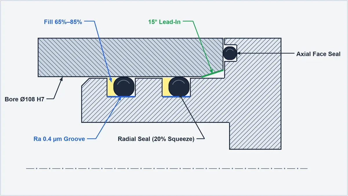
To guarantee sealing from 0.05 bar surface splash to full ocean depth, subsea bulkheads combine dual radial piston O-rings (20% squeeze, 65%–85% groove fill on Ra 0.4 µm grooves) and a 15° lead-in chamfer with an axial face seal under the flange shoulder (as illustrated in the 2D cross-section schematic below).
Static vs. Dynamic Gland Squeeze & Anti-Extrusion Clearance
For static subsea radial piston and axial face glands using 70–90 Shore A nitrile butadiene rubber (NBR) or fluoroelastomer (FKM) rings, we machine gland depth for 15%–25% cross-sectional squeeze and size groove width for 65%–85% gland fill. Exceeding 85% fill locks the elastomer hydraulically and splits the groove wall.
Conversely, dynamic rotary thruster shaft seals or linear compensator pistons require a lighter 10%–18% radial squeeze paired with spring-energized polytetrafluoroethylene (PTFE) lip seals or oil-filled pressure-compensated bladders to prevent stick-slip tearing. Above 10 MPa (100 bar / 1,450 psi), contoured PTFE or PEEK anti-extrusion backup rings are mandatory on the low-pressure downstream side.
At depths beyond 1,000 m (10.05 MPa / 1,458 psi), the diametral clearance gap between the bulkhead spigot outer diameter (typically g6 or f7 shaft fit) and the housing bore (H7) must be held within 0.030–0.065 mm (0.0012″–0.0026″) so high-pressure seawater cannot extrude 70 Shore A elastomer into the radial clearance gap.
Entry Chamfers, Groove Corner Radii & Wet-Mate Penetrator Ports
Crucially, every radial receiver tube bore must include a smooth, burr-free 15°–20° lead-in entry chamfer minimum 1.5–2.0 mm (0.060″–0.080″) long blended with a 0.3 mm (0.012″) corner radius. Without a gentle lead-in ramp, the sharp bore mouth shears a crescent-shaped sliver off the O-ring crown during bulkhead insertion.
Inside the rectangular O-ring gland itself, internal bottom corner radii should be controlled to R 0.20–0.40 mm (0.008″–0.016″) for AS568-2xx series grooves, while the top groove lip edges must be deburred to a smooth R 0.08–0.15 mm (0.003″–0.006″) break without undercutting the retaining sidewall height.
Sealing groove floors and sidewalls must be precision-turned to Ra 0.4–0.8 µm (16–32 µin) with a strictly concentric circumferential tool lay running parallel to the O-ring centerline. For specialized grooving insert geometries, chip evacuation, and chatter control, see our dedicated CNC O-ring grooving machining and Design for Manufacturability (DFM) guide.
Finally, bulkhead end-caps incorporate threaded M10×1.5-6H, M12×1.5-6H, or 7/16″-20 UNF-2B subsea wet-mate cable penetrator ports. Each port requires a precision spotfaced seating counterbore machined to Ra 0.8 µm (32 µin), flatness ⏥ 0.015 mm (0.0006″), and perpendicularity ⊥ 0.015 mm (0.0006″) relative to the thread pitch cylinder so the penetrator face O-ring compresses uniformly.
4. 5-Axis CNC Thruster Ducts, Propellers & Single-Point Diamond-Turned (SPDT) Optical PMMA Viewport Domes
In real-world subsea production, 80% of ROV structural brackets, ballast plates, and cylindrical pressure tubes are most cost-effectively manufactured on rigid 3-axis and 4-axis CNC milling centers and turn-mill lathes. Reserve simultaneous 5-axis CNC machining strictly for components where compound hydrodynamic curvature or zero-reclamping datum integrity directly dictates performance.
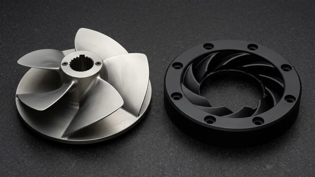
Simultaneous 5-axis contouring is essential for high-efficiency Kort-nozzle thruster rotors and radial stator rings. Continuous 5-axis ball-nose toolpaths (0.08–0.15 mm stepover) generate twisted hydrofoil blades and smooth tangent blade-root fillets that suppress cavitation (as shown in the 5-axis milled Ti-6Al-4V rotor and hard-anodized 7075-T651 stator pair below).
Hydrodynamic Rotor Balance, Feeds & Speeds & Stator Tip Clearance
When machining Ti-6Al-4V or 7075-T651 thruster rotors operating at 1,800–3,500 RPM in water, blade-to-blade pitch indexing error and hub bore concentricity must be held within ◎ 0.012 mm (0.0005″). This maintains radial tip clearance inside the surrounding stator shroud at 0.25–0.40 mm (0.010″–0.016″) without blade rub or magnetic-coupling cogging.
In our in-house 5-axis machining center practice, when finishing thin Ti-6Al-4V hydrofoil blades, we apply climb milling at Vc = 55–75 m/min (180–246 SFM) and fz = 0.04–0.07 mm/tooth (vs. Vc = 260–380 m/min for 7075-T651) with high-pressure coolant to prevent work hardening layer buildup, notch wear, and tool deflection.
Optical Cast PMMA Viewport Domes: Annealing & SPDT Protocol
Subsea camera and laser-scaler viewports represent the second critical machining challenge. Hemispherical optical domes made from cell-cast PMMA (polymethyl methacrylate / acrylic) offer a refractive index (n ≈ 1.49) close to seawater (n ≈ 1.34) and resist hydrostatic compression by transferring radial water load directly into an annular metallic retainer bezel.
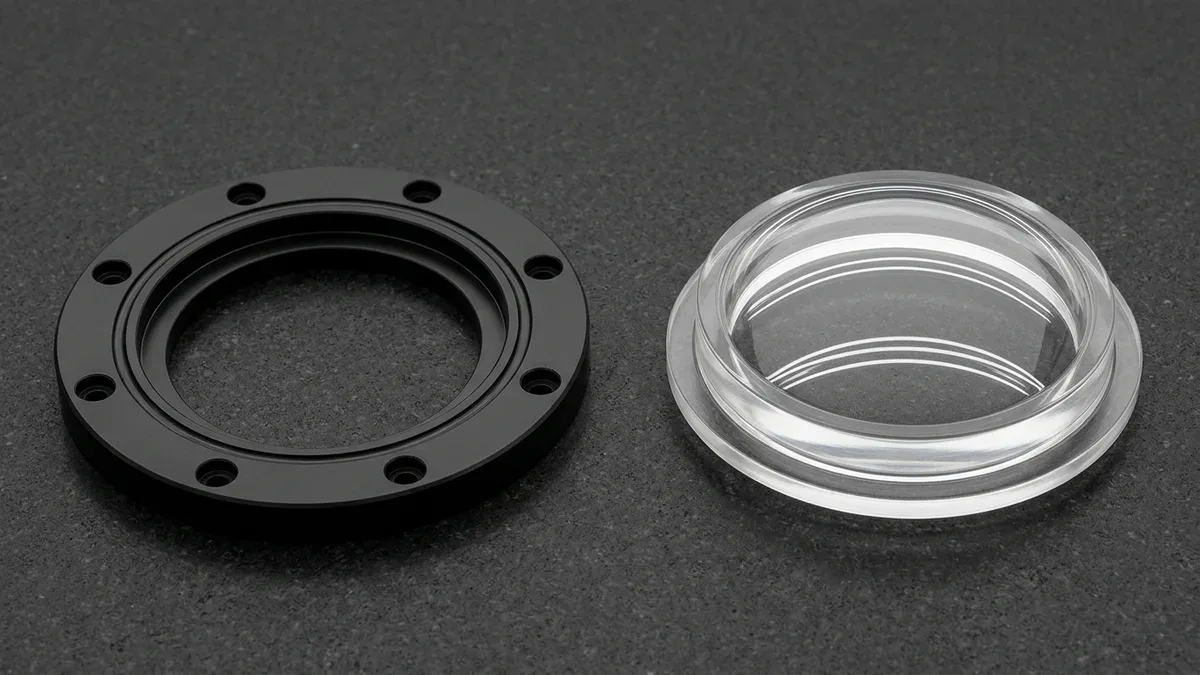
However, optical precision machining and diamond turning of cast PMMA requires a strict thermal-and-mechanical sequence. Without stress-relief annealing, a stepped PMMA dome ring seated against a hard-anodized 6061-T651 O-ring retainer bezel (as shown in the mating optical viewport assembly below) will develop micro-crazing fractures under cyclic hydrostatic compression.
Our optical plastic machining cell executes a mandatory four-stage sequence for subsea PMMA viewport domes and flat ports:
- Semi-Finish Turning with Flood Emulsion Coolant: Machine optical cell-cast PMMA billet leaving a uniform 0.30 mm (0.012″) semi-finish allowance using razor-sharp high-positive rake polycrystalline diamond (PCD) tooling with non-aromatic water-soluble emulsion coolant.
- Annealing for Isothermal Stress Relief at 70–80°C: Soak the semi-finished PMMA dome in a programmable forced-convection oven at 70–80°C (158–176°F) for 2–4 hours (depending on wall thickness), followed by a slow ramp-down (≤ 10°C/hour / 18°F/hour) to eliminate internal shear stress.
- Single-Point Diamond Turning (SPDT) or Buffing to SPI A-1: Finish-turn the optical hemisphere on an ultra-precision diamond lathe to Ra ≤ 0.010 µm (0.4 µin), or execute progressive wet sanding from #800 through #5000 grit followed by sub-micron SPI A-1 diamond-paste optical buffing (Ra 0.015–0.025 µm) for ≥ 92% light transmission.
- Prohibiting Flame Polishing & DCM Vapor Smoothing on PMMA: We never apply open-flame polishing or dichloromethane (DCM) chemical vapor smoothing to PMMA subsea domes, as both induce tensile surface embrittlement and immediate solvent crazing (DCM vapor polishing is restricted exclusively to non-structural amorphous polycarbonate or Ultem PEI parts).
5. Galvanic Corrosion Isolation, Type III Hard Anodizing & 3.5–6.0 Bar Pressure-Decay Testing
When an ROV enters seawater (~3.5% salinity, ~5 S/m conductivity), electrical continuity between dissimilar metals forms an active galvanic cell. Because aluminum 6061-T651 sits near −0.76 V to −0.90 V versus a saturated calomel electrode (SCE) while passive 316L stainless steel sits near −0.05 V to −0.10 V, the ~0.70 V gap rapidly dissolves anodic aluminum.
This electrochemical gap becomes especially destructive when small-area aluminum tapped holes or thin anodized mounting ears are bolted directly to large-area 316L manipulator arms or titanium thrusters (an unfavorable cathode-to-anode surface-area ratio). Below is our shop-floor diagnostic and engineering countermeasure loop for subsea hardware assemblies:
- Symptom: White aluminum hydroxide gel, seized 316L socket head cap screws, and severe thread stripping or O-ring groove pitting around bulkhead mounting flanges after only 40–80 hours of salt-water immersion.
- Root Cause: Stainless steel bolt heads or clevis yokes crushed through the brittle anodic oxide layer at sharp hole edges, completing an electrical circuit through seawater trapped inside unsealed through-tapped holes.
- Corrective Action: Break all sharp bore edges with a controlled 0.2–0.4 mm (0.008″–0.016″) radius or chamfer prior to anodizing; replace open through-tapped holes with blind tapped holes coated in marine anti-seize; and press-fit CNC-turned PEEK flanged isolator bushings (1.5–4.0 mm / 0.060″–0.157″ wall) into every dissimilar-metal joint (as shown in the bead-blasted 316L manipulator clevis fork yoke and warm-beige PEEK flanged isolator bushing pair below).
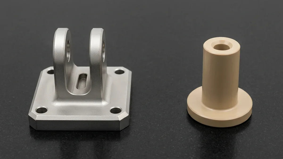
For aluminum ROV hulls, 50 µm (0.0020″) MIL-A-8625 Type III hardcoat (450–550 HV0.05) shrinks H7 bores by 0.050 mm and roughens O-ring grooves toward Ra 0.8–1.1 µm, requiring silicone masking per our aluminum anodizing and masking guide.
20°C ± 1°C Zeiss CMM Metrology & Pneumatic Pressure-Decay Qualification
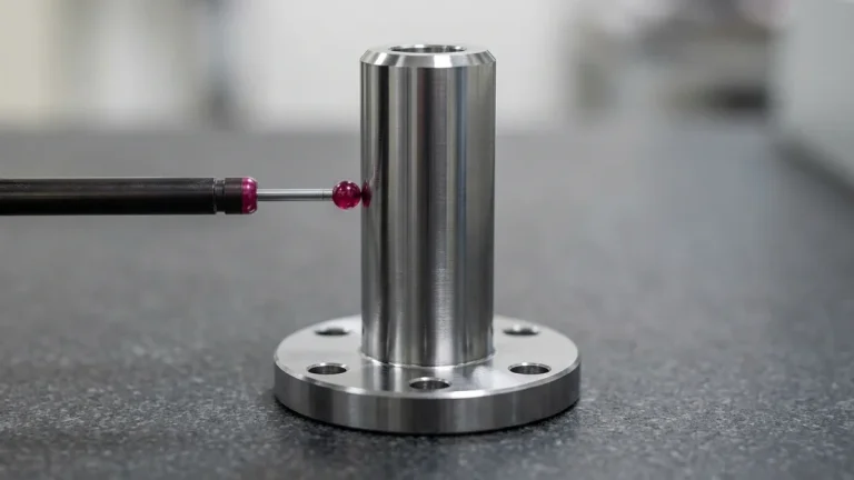
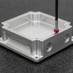
Prior to dispatch, our inspection lab verifies bore cylindricity, true position, and thermal expansion drift inside a 20°C ± 1°C (68°F ± 1.8°F) metrology room using a Zeiss Contura Coordinate Measuring Machine (CMM) and contact profilometers for First Article Inspection (FAI).
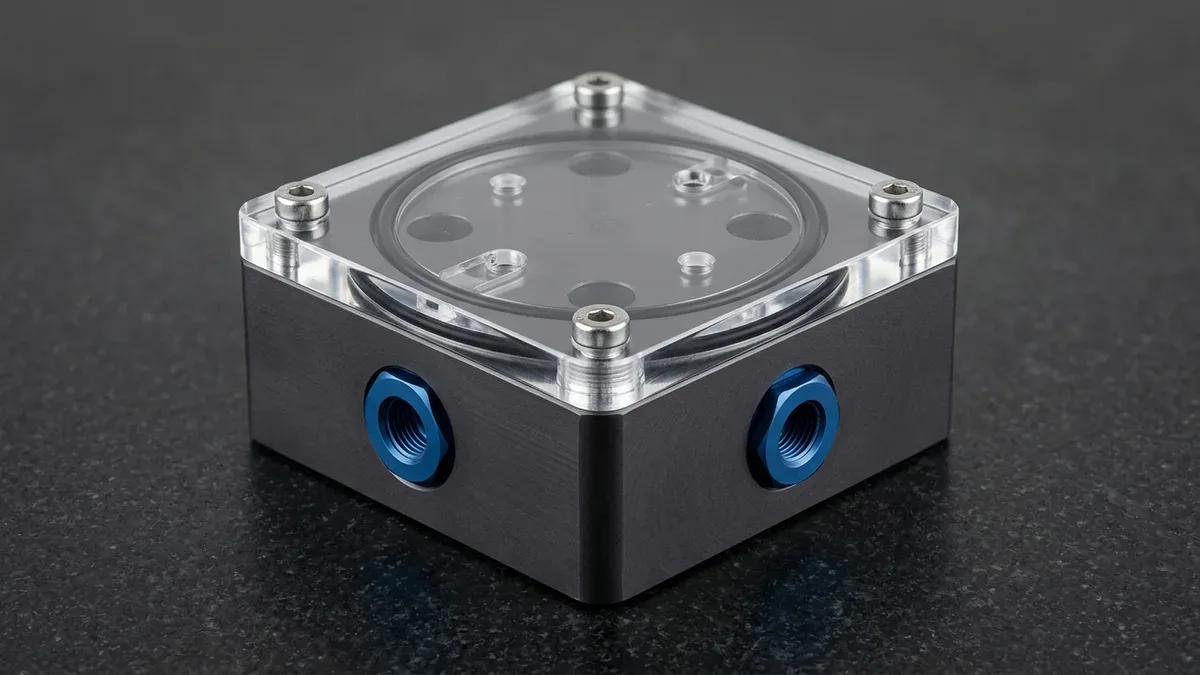
Every sealed ROV housing and sensor manifold then undergoes in-house 3.5–6.0 bar (50.8–87.0 psi) dry-air pneumatic pressure-decay or submerged water-bubble leak testing using a transparent acrylic sealing plate, elastomer O-ring, and anodized quick-disconnect test plugs (as shown on the 6061-T651 manifold assembly below).
6. Prototyping to Fleet Production: DFM Checklist & When NOT to Use Unsealed 7075 Aluminum or 303 Stainless Steel in Seawater
Transitioning an underwater ROV from a single pool-test prototype to a 20–100+ unit commercial inspection fleet requires eliminating fragile material selections and standardizing O-ring tooling across sub-assemblies. Two common material specification traps repeatedly cause field failures during early ocean trials:
- When NOT to Use 303 Free-Machining Stainless Steel: Engineers occasionally specify 303 stainless steel for subsea shafts or penetrator plugs to reduce CNC turning cycle times. However, the 0.15%–0.35% sulfur added to 303 for chip breaking forms manganese sulfide (MnS) inclusions that dissolve rapidly in chloride seawater, triggering catastrophic tunnel pitting within days; always mandate 316L (UNS S31603) or 2205 Duplex stainless steel.
- When NOT to Use Unsealed or Thin-Anodized 7075-T651 in Long-Duration Seawater Moorings: Do not specify bare, clear Type II anodized, or unmaintained 7075-T651 for subsea housings deployed longer than single-dive missions without sacrificial zinc anodes. If higher yield strength than 6061-T651 is mandatory without stepping up to Ti-6Al-4V, specify over-aged 7075-T7351 with sealed 50 µm Type III hardcoat and polyurethane marine topcoat.
Before releasing 3D Computer-Aided Design (CAD) STEP/IGES packages and 2D Geometric Dimensioning and Tolerancing (GD&T) prints for low-volume fleet production, execute this four-step subsea DFM verification workflow:
- Standardize AS568 Dash Numbers & Groove Widths: Consolidate bulkhead radial and axial seals onto standard AS568-2xx (3.53 mm CS) or AS568-3xx (5.33 mm CS) dash sizes so standard carbide grooving blades machine all glands without custom ground form tools.
- Explicitly Call Out Pre- vs. Post-Anodize Dimensions: State clearly on the 2D drawing title block whether H7 (+0/+IT7) bores and O-ring gland depths apply after 50 µm Type III hard anodizing or whether sealing bores must be silicone-plug masked.
- Eliminate Blind Crevice Traps & Sharp Anodizing Corners: Replace stagnant unsealed lap joints with drainage reliefs or O-ring sealed faces, and call out 0.2–0.4 mm (0.008″–0.016″) edge breaks on all external anodized aluminum edges.
- Specify Subsea Inspection & Leak-Test Acceptance Criteria: Define target CMM datum schemes, Ra 0.4–0.8 µm groove surface roughness checks, and 3.5–6.0 bar pneumatic pressure-decay hold durations (typically ≤ 0.01 bar drop over 30 minutes) on the purchase specification.
| ROV Subsystem Component | Primary CNC Process | Critical GD&T & Tolerance (mm / in) | Mandatory Surface Treatment | Ex-Factory Turnaround* & Recommended Application / When to Choose |
|---|---|---|---|---|
| Cylindrical Pressure Hull & End-Cap Bulkheads | CNC Turning + 4-Axis Turn-Mill Center | Bore H7 (+0/+IT7), Cylindricity ⌭ 0.010 mm, Groove ±0.015 mm, Ra 0.4–0.8 µm | 50 µm MIL-A-8625 Type III Hardcoat (450–550 HV0.05) + Masked Bores | 7 ~ 12 Business Days (Prototypes) / 12 ~ 25 Business Days (Batch); best for 100–600 m dry avionics & battery housings |
| Twisted Hydrofoil Thruster Rotor & Stator Ring | Simultaneous 5-Axis CNC Milling + Turning | Hub Bore ±0.010 mm (±0.0004″), Runout 0.015 mm, Blade Profile ±0.025 mm | Ti-6Al-4V As-Milled / Vibratory Polished (Ra 0.8 µm) or 7075 Type III Hardcoat | 7 ~ 12 Business Days (Prototypes) / 15 ~ 30 Business Days (Batch); best for high-RPM cavitation-resistant vector thrusters |
| Optical Cast PMMA Camera Viewport Dome | CNC Diamond Turning (SPDT) + Thermal Annealing | Flange Seat ±0.020 mm (±0.0008″), Wall Uniformity ±0.030 mm, Optical Ra ≤ 0.025 µm | 70–80°C Stress-Relief Anneal + #800–#5000 Wet Sand & SPI A-1 Diamond Buff | 7 ~ 12 Business Days (Optical Polish) / 12 ~ 25 Business Days (Fleet); best for distortion-free subsea HD camera & LiDAR ports |
| 316L Manipulator Clevis & PEEK Isolator Bushings | 3/4-Axis VMC Milling + Swiss/CNC Turning | Pivot Bore Ø10 H7 (+0/+0.015 mm), Coaxiality ◎ 0.012 mm, General ISO 2768-mK | Fine Glass-Bead Blast (Ra 1.6 µm) + Citric/Nitric Acid Passivation per ASTM A967 | 4 ~ 8 Business Days (As-Machined PEEK) / 7 ~ 12 Business Days (316L); best for high-load articulated grabber linkages |
| Open-Frame HDPE / POM-C Skids & Sensor Mounts | 3-Axis High-Speed CNC Routing & Milling | Hole True Position ⌖ Ø0.050 mm (0.0020″), General Linear per ISO 2768-mK | De-burred As-Machined Finish (Ra 1.6–3.2 µm) with Chamfered Cable Routing Slots | 4 ~ 8 Business Days (Rapid Prototypes) / 7 ~ 15 Business Days (Batch); best for impact-absorbing modular chassis frames |
*Note: All lead times above denote Ex-Factory Production & Inspection Turnaround (including CMM metrology and pneumatic leak testing) and are strictly separate from international air express transit (DHL/FedEx/UPS 3 ~ 5 Days Air Transit). Quote and DFM engineering feedback are delivered Within 24 Hours.
7. Technical Engineering FAQ
How do you compensate AS568 O-ring glands and H7 bores for MIL-A-8625 Type III hard anodizing on aluminum ROV housings?
A 50 µm (0.0020″) MIL-A-8625 Type III hardcoat penetrates 25 µm inward and grows 25 µm (0.0010″) outward per surface, shrinking bore diameters by 50 µm. Our machinists either pre-compensate turning dimensions by +0.050 mm (+0.0020″) on diameter or mask H7 bores with silicone plugs.
Why should flame polishing and DCM vapor polishing be avoided on CNC-machined PMMA acrylic ROV viewport domes?
Flame polishing and dichloromethane (DCM) vapor treatments induce residual tensile surface stress in cell-cast PMMA acrylic, causing micro-crazing and brittle implosion under cyclic hydrostatic loading. Instead, we anneal machined PMMA domes at 70–80°C (158–176°F) before executing SPDT diamond turning or #800–#5000 wet sanding with SPI A-1 buffing.
How do you prevent galvanic corrosion when bolting 316L stainless steel thrusters or manipulators to 6061-T651 aluminum ROV frames?
Direct metallic contact between passivated 316L stainless steel and 6061-T651 aluminum in conductive seawater creates a ~0.70 V electrochemical cell that rapidly pits the anodic aluminum threads. We isolate dissimilar joints using CNC-turned PEEK shoulder bushings, dielectric thrust washers, and blind tapped holes sealed with marine anti-seize.
What surface roughness and machining lay are required inside AS568 static O-ring grooves for subsea ROV bulkhead seals?
Static subsea AS568 O-ring grooves require a sealing floor and wall roughness of Ra 0.4–0.8 µm (16–32 µin) with a concentric lathe-turned lay parallel to the O-ring circumference. Transverse tool scratches or 3-axis milling stepover cusps across the groove width create capillary leak paths under hydrostatic pressure.
Ready to Machine Your Subsea ROV Pressure Hulls & Thruster Hardware?
Upload your 3D CAD models (STEP/IGES) and 2D tolerance drawings to our in-house engineering team for a comprehensive manufacturability review on AS568 O-ring glands, MIL-A-8625 Type III hard-anodize masking, and optical PMMA dome polishing.
Upload CAD Drawings for a Technical DFM Review & Quote →