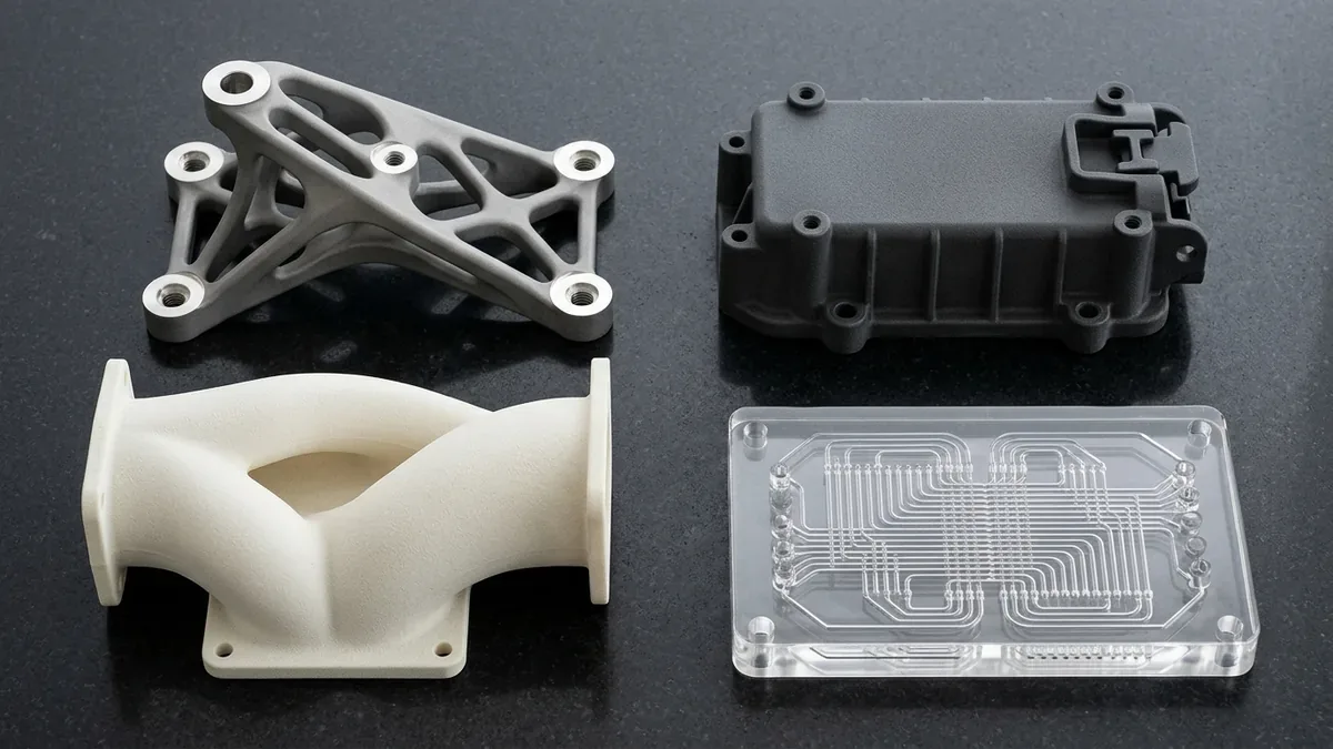
Understanding 3D printing tolerances determines whether additive components assemble smoothly on the first build cycle. Consequently, miscalculating layer shrinkage and laser spot kerf leads to binding shafts, loose snap-fits, and expensive reprints.
Every additive manufacturing technology establishes a distinct physical accuracy threshold. Furthermore, utilizing industrial 3D printing services guarantees calibrated process control across polymer resins, nylon powders, and laser-sintered alloys.
When engineering designs demand precision bearing journals or ground sealing lands, polymer printing alone proves insufficient. Specifically, combining additive preforms with secondary CNC machining delivers tight ±0.010 mm (±0.0004″) mating tolerances and ISO 2768-mK general accuracy.
Executive Summary & Engineering Takeaways (BLUF)
- Core Focus & DFM Scope: Actionable shop-floor engineering guidelines for 3D Printing Tolerances, covering material selection, geometric tolerancing, and defect prevention.
- Dimensional Accuracy Baseline: Industrial SLA/DLP holds ±0.10 mm (±0.004″); SLS/MJF nylon holds ±0.20 mm per 100 mm (±0.002″/in); DMLS metal builds + secondary CNC mating interfaces hold ±0.010 mm (±0.0004″).
- Layer Resolution & Post-Finishing: Build layers from 25–100 µm (0.001″–0.004″) upgraded via media tumbling, vapor smoothing, bead blasting (#120 glass bead), or 3/4/5-axis CNC datum skimming.
- Build Orientation & Metrology: Strategic Z-axis orientation to minimize staircase anisotropy and thermal distortion, verified via 2.5D optical vision metrology (VMS), Go/No-Go pin gauging, and tactile CMM probing on CNC post-machined metal datums.
- Ex-Factory Turnaround: 4 to 8 business days for raw/unfinished additive prototypes; 7 to 12 business days for vapor-smoothed, plated, or hybrid CNC post-machined parts (excluding 3–5 days air transit).
Article Engineering Navigation
- 1. What Governs 3D Printing Tolerances?
- 2. 3D Printing Tolerances by Technology Matrix
- 3. Clearance Guidelines for Additive Assemblies
- 4. Recommended Mating Fit Clearances
- 5. Why Do 3D Printing Tolerances Parts Suffer From Z-Axis Anisotropy or Thermal Distortion, and How Do You Compensate?
- 6. Technical Engineering FAQ
1. What Governs 3D Printing Tolerances?
Additive manufacturing constructs components incrementally through liquid resin photopolymerization, powder sintering, or thermoplastic extrusion. Specifically, four thermal and physical mechanisms influence final part dimensions.
First, volumetric cooling shrinkage contracts polymers as molten pools crystallize. Therefore, CAD engineers must incorporate empirical scaling factors to compensate for thermal shrinkage.
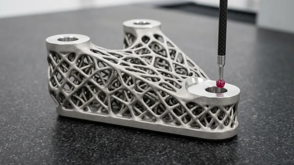
Second, build orientation dictates directional accuracy. In particular, X/Y laser scanning achieves tighter resolution than incremental Z-axis layer stacking.
2. 3D Printing Tolerances by Technology Matrix
Engineers select additive processes by comparing achievable tolerances, surface finishes, and minimum feature sizes. To illustrate, review the technology matrix below:
| Additive Technology | X / Y Tolerance (mm) | Z-Axis Tolerance (mm) | Minimum Wall (mm) | Thermal Shrinkage (%) | Optimal Application |
|---|---|---|---|---|---|
| SLA (Stereolithography) | ±0.05 mm to ±0.10 mm | ±0.05 mm | 0.6 mm | 0.3% to 0.5% | Clear optical lenses, master casting patterns |
| SLS (Selective Laser Sintering) | ±0.20 mm to ±0.30 mm | ±0.30 mm | 0.8 mm | 2.5% to 3.5% | Durable nylon housings, complex ducting |
| MJF (Multi Jet Fusion) | ±0.20 mm or ±0.2% | ±0.25 mm | 0.8 mm | 2.0% to 3.0% | End-use automotive brackets, fluid manifolds |
| DMLS / SLM (Metal Printing) | ±0.10 mm to ±0.20 mm | ±0.15 mm | 0.4 mm | 1.5% to 2.5% | Titanium aerospace brackets, turbine nozzles |
| Industrial FDM (FGF) | ±0.25 mm to ±0.50 mm | ±0.30 mm | 1.2 mm | 0.8% to 2.0% | Large structural jigs, factory fixtures |
3. Clearance Guidelines for Additive Assemblies
A 3D CAD model contains zero mechanical interference by default. However, physical parts require intentional clearance offsets to compensate for powder adhesion and bead swell.
For example, printed cylindrical holes consistently measure 0.10 to 0.25 mm undersized. Consequently, designers oversize internal hole diameters in the original 3D model.
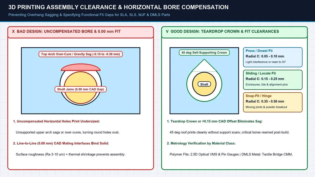
Similarly, snap-fit cantilevers require dedicated flexure allowances. Thus, modeling appropriate beam thickness prevents plastic fatigue during repeated latch cycles.
4. Recommended Mating Fit Clearances
Engineers design specific gap clearances based on intended assembly kinematics. To illustrate, review the clearance recommendations below:
| Joint Type | SLA Clearance (per side) | SLS / MJF Clearance | DMLS Metal Clearance | Engineering Recommendation |
|---|---|---|---|---|
| Press / Interference Fit | -0.02 to -0.05 mm actual interference (0.00 to +0.03 mm CAD offset for cure bloom) | -0.05 to -0.10 mm actual interference (+0.05 to +0.08 mm CAD offset for sinter skin) | -0.010 to -0.035 mm interference (CNC reamed H7 bore +0.015/-0.000 mm & p6 shaft) | Post-ream DMLS metal bores to H7; add lead-in chamfer to prevent binding |
| Close Sliding Fit | 0.10 to 0.15 mm | 0.20 to 0.30 mm | 0.15 to 0.25 mm | Vapor smoothing reduces sliding friction |
| Free Clearance Fit | 0.20 to 0.30 mm | 0.35 to 0.50 mm | 0.30 to 0.40 mm | Ideal for linkages and loose pivot pins |
| Snap-Fit Cantilever | 0.15 to 0.20 mm | 0.25 to 0.35 mm | N/A (Metals too rigid) | Align cantilever parallel to build plate |
| Fastener Clearance Hole | +0.20 mm diameter | +0.40 mm diameter | +0.30 mm diameter | Specify brass heat-set inserts for threads |
5. Why Do 3D Printing Tolerances Parts Suffer From Z-Axis Anisotropy or Thermal Distortion, and How Do You Compensate?
Controlling dimensional fidelity in 3D Printing Tolerances requires compensating for layer-by-layer thermal contraction, staircase stepping, and support-interface stress concentration. While in-plane XY features maintain ±0.10 to ±0.20 mm (±0.004″ to ±0.008″), unsupported overhangs below 45° and unmachined bearing bores exhibit out-of-roundness that demands hybrid CNC post-machining.
Shop-Floor Quantitative Derivation: Staircase Cusp Height & Hybrid Machining Stock Allowance
In our additive manufacturing and post-processing shop, achieving functional assembly fits in 3D Printing Tolerances depends on quantifying the geometric cusp height (hcusp) across inclined surfaces and leaving adequate machining stock on datum interfaces. For a surface inclined at angle θ = 20° relative to the build platform, printed at a layer thickness tlayer = 0.050 mm (50 μm / 0.002″), the theoretical staircase cusp height is:
hcusp = tlayer × cos(θ) = 0.050 mm × cos(20°) = 0.047 mm (0.00185″)
Because a 0.047 mm staircase step coupled with ±0.15 mm (±0.006″) thermal shrinkage exceeds precision press-fit or O-ring sealing limits, critical bores and flat mating pads are modeled with +0.50 to +0.80 mm (+0.020″ to +0.031″) sacrificial stock. After stress-relief annealing, the part is indicated on a 3-axis or 4-axis VMC using custom 3D-contoured soft jaws and finish-bored to ±0.010 mm (±0.0004″) and Ra 0.8 μm (32 μin).
Step-by-Step Shop-Floor Execution & Quality Protocol
To bridge CAD intent with repeatable shop-floor delivery, our engineering team enforces a four-stage execution workflow across every prototype and low-volume production batch:
- Step 1: Build Orientation & Support Vector Optimization: Orient critical datum surfaces and cylindrical bores parallel or perpendicular to the Z-axis to eliminate ovality, while angling thin walls ≥45° to minimize support contact scars.
- Step 2: Escape Hole & Powder/Resin Evacuation Verification: Integrate minimum ∅3.0 to ∅5.0 mm (0.118″ to 0.197″) drainage ports in hollow lattices and internal manifolds so trapped unmelted powder or liquid photopolymer can be 100% evacuated.
- Step 3: Thermal Stress-Relief Before Support Removal: For DMLS/SLM metal builds, execute furnace stress-relief annealing while the component remains anchored to the heavy steel build plate to prevent cantilever springback.
- Step 4: Hybrid CNC Datum Skimming & Surface Finishing: Mill reference datums, ream H7 dowel holes, tap M-series/UN threads on CNC centers, and apply bead blasting (#120 glass media) or vapor smoothing prior to 2.5D optical vision (VMS) inspection and tactile CMM verification on CNC post-machined metal datums.
Shop-Floor Defect Troubleshooting & Corrective Action Matrix
When evaluating part geometry during pre-production DFM review, our manufacturing engineers screen for the following failure modes and apply proven corrective controls:
| Defect / Symptom | Physical Root Cause | Shop-Floor Corrective Action | Recommended DFM Spec Limit |
|---|---|---|---|
| Z-Axis Delamination & Cracking | Excessive inter-layer thermal gradients or insufficient laser/exposure cross-linking energy | Preheat build chamber to material glass-transition window, utilize chessboard island scan vectors, and anneal prior to wire-EDM plate removal. | Inter-layer density ≥ 99.5% |
| Cylindrical Bore Ovality (Droop) | Horizontal axis orientation causing top-arch sagging across unsupported bridge spans | Re-orient bore axes vertically (parallel to Z) or undersize by 0.6 mm (0.024″) and precision-ream after printing. | Cylindricity ≤ 0.015 mm |
| Trapped Powder / Uncured Resin | Dead-end internal channels or blind pockets lacking dual escape ports for air/solvent purge | Add dual opposing ∅4.0 mm (0.157″) cleanout ports and flush internal passages with ultrasonic cavitation and compressed nitrogen. | Min channel ∅ ≥ 1.5 mm |
| Staircase Roughness on Slopes | Shallow inclination angles (5°–25°) magnifying layer stepping across contoured surfaces | Tilt part orientation to 35°–45°, reduce layer height to 25–30 μm (0.001″), and apply chemical vapor smoothing or vibratory tumbling. | Post-finish Ra 0.8–1.6 μm |
Engineering Trade-Offs: When NOT to Over-Specify
When to Avoid This Process (Engineering Limitations): Avoid relying purely on raw additive manufacturing when components consist of simple prismatic plates, shafts, or structural brackets requiring isotropic fatigue strength, mirror surface finishes (Ra ≤ 0.4 μm / 16 μin), or tight tolerances (±0.010 mm / ±0.0004″) across all faces.
For prismatic geometries without internal conformal channels or organic lattices, direct 3-axis and 4-axis CNC machining from wrought 6061-T6, 7075-T651, or 316L bar stock is faster, stronger along the Z-axis, and more economical above 10–20 units.
🔗 Related Additive & Hybrid CNC Engineering Guides:
For production programs involving 3D Printing Tolerances, combining near-net additive builds with precision 3-axis and 4-axis CNC datum skimming unlocks ±0.010 mm (±0.0004″) bearing fits. Compare process trade-offs in our SLM Metal vs. SLA Resin Engineering Comparison, evaluate hybrid tooling workflows in Will 3D Printing Replace Rapid Tooling?, and specify post-finish roughness per our Surface Texture & Roughness Standards (Ra vs. Rz) Guide.
6. Technical Engineering FAQ
Stereolithography (SLA) delivers the tightest tolerances among polymer processes, holding plus-minus 0.05 mm in X/Y and Z. The ultra-fine UV laser spot cures photopolymer liquid with minimal thermal distortion. At AS Prototypes, our engineering team validates these parameters against ISO 2768-mK general tolerances (with critical mating features held to ±0.010 mm / ±0.0004″) and provides 24-hour DFM feedback.
Sintered powder adhesion, laser beam kerf, and thermoplastic melt swell displace inward into circular toolpaths. Consequently, engineers model internal holes roughly 0.2 to 0.4 mm oversize. At AS Prototypes, our engineering team validates these parameters against ISO 2768-mK general tolerances (with critical mating features held to ±0.010 mm / ±0.0004″) and provides 24-hour DFM feedback.
Engineers print near-net shapes with 0.5 to 1.0 mm machining stock on critical bores. Subsequently, secondary CNC milling or precision reaming establishes exact ISO 286 H7 bearing fits (±0.010 mm / ±0.0004″), while general unmated features conform to ISO 2768-mK. At AS Prototypes, our engineering team validates these parameters against ISO 2768-mK general tolerances (with critical mating features held to ±0.010 mm / ±0.0004″) and provides 24-hour DFM feedback.
Accelerate Hardware Validation with Industrial 3D Printing & Hybrid CNC
Bridge additive design freedom with precision CNC datum finishing and polyurethane vacuum casting. Upload your 3D CAD assemblies (STEP/IGES/STL) to evaluate material selection, functional tolerances, and batch unit economics.
Request an Additive & Prototyping DFM Analysis