Transforming an innovative concept into a commercially viable hardware product requires disciplined engineering execution. Therefore, professional product design integrates creative industrial design with rigorous mechanical engineering. Market success demands more than attractive exterior styling. Products must withstand real-world operational stresses, comply with safety regulations, and scale economically.
Without structured engineering workflows, hardware ventures encounter costly late-stage tooling revisions and assembly failures. In addition, manufacturing complexities often delay critical product launches. In this engineering guide, we examine the complete hardware development lifecycle. Furthermore, we explore DFM optimization, prototyping stages, and production scaling methodologies.
1. Industrial Design vs Mechanical Engineering: Unifying Form and Function
Successful hardware products achieve seamless synergy between aesthetic beauty and internal mechanical functionality. Industrial designers establish user ergonomics, visual styling languages, and intuitive human-machine interfaces. Consequently, initial sketches define emotional appeal and tactile brand identity. However, mechanical engineers must translate these surfaces into production-ready solid CAD models.
Engineers evaluate internal packaging constraints, battery volumes, and printed circuit board clearances. In addition, finite element analysis validates structural load paths and impact drop resistance. For advanced consumer electronics, our consumer electronics and appliance solutions ensure thermal heat sinks dissipate processor heat effectively. Thus, thermal management never compromises exterior industrial styling.
2. Design for Manufacturing (DFM) and Assembly Optimization
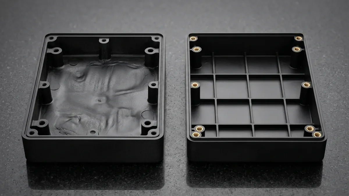
DFM serves as the critical bridge connecting conceptual design with factory mass manufacturing. Early DFM reviews identify problematic geometry flaws before cutting expensive production steel molds. For injection molded plastics, engineers ensure uniform nominal wall thicknesses. This uniform thickness prevents sink marks, differential cooling warpage, and cosmetic blemishes.
Moreover, engineers apply adequate draft angles to internal ribs and textured cosmetic sidewalls. Minimum draft angles of one to two degrees guarantee clean part ejection without drag marks. In addition, Design for Assembly rules consolidate individual parts into integrated snap-fit modules. Consequently, fastener counts decrease, reducing factory assembly labor and warranty claims significantly.
The structured phases and core deliverables of the professional hardware development lifecycle are detailed below.
| Development Phase | Key Engineering Activities | Primary Phase Deliverables | Critical Decision Gate |
|---|---|---|---|
| Phase 1: Concept & Styling | Ergonomic research, user personas, hand sketching. | Styling mood boards and initial aesthetic clay models. | Industrial design concept sign-off. |
| Phase 2: Detailed CAD & DFM | Parametric 3D solid modeling, tolerance stack-ups. | Master 3D CAD assembly files and 2D engineering drawings. | Engineering feasibility approval. |
| Phase 3: Functional Prototyping | Additive manufacturing, CNC machining, bench testing. | Alpha and beta physical functional prototypes. | Drop, thermal, and compliance validation. |
| Phase 4: Tooling & Pilot Run | Mold flow analysis, rapid tooling fabrication. | First Article Inspection parts and pilot assembly runs. | Process capability and Cpk confirmation. |
| Phase 5: Full Mass Production | Automated mass manufacturing, packaging, QC audits. | Packaged end-use goods ready for global commercial distribution. | Final production handover and ramp-up. |
3. Strategic Prototyping: From Proof of Concept to Production Part Approval
Physical prototypes serve distinct technical functions across successive product development milestones. Early appearance models verify physical scale, button ergonomics, and color, material, and finish palettes. Meanwhile, functional engineering prototypes undergo destructive vibration, ingress protection, and thermal environmental chambers. Consequently, design teams resolve functional discrepancies prior to high-volume commitments.
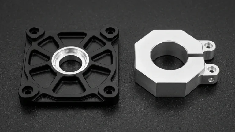
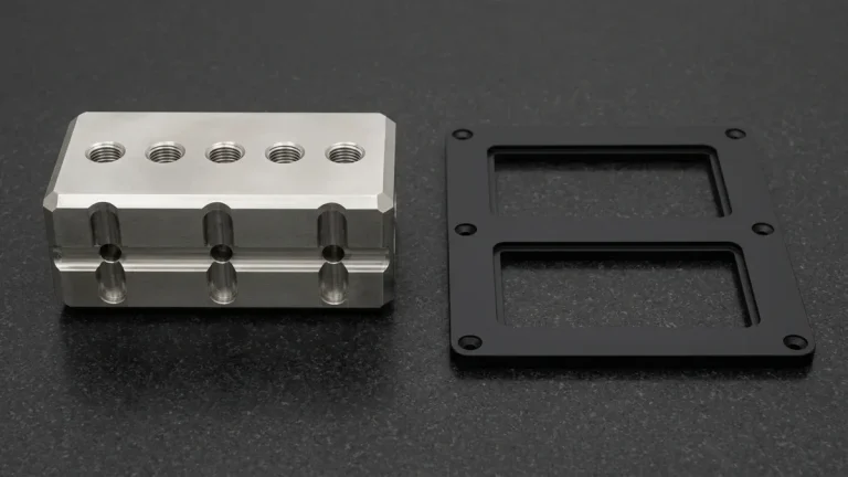
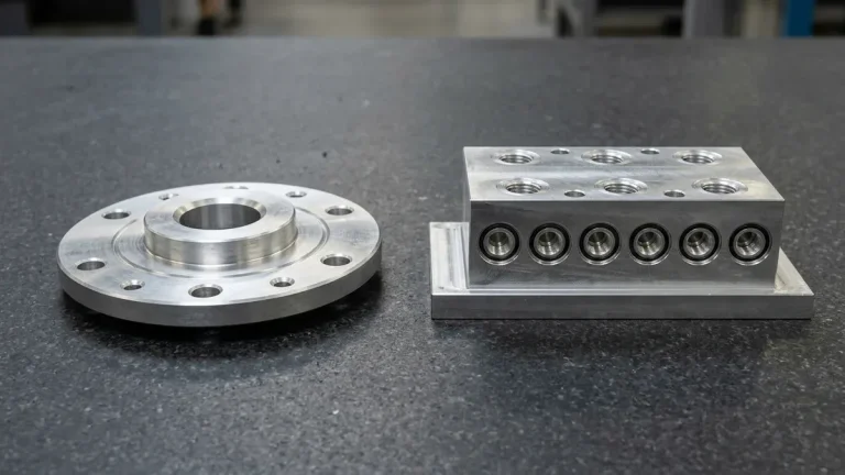
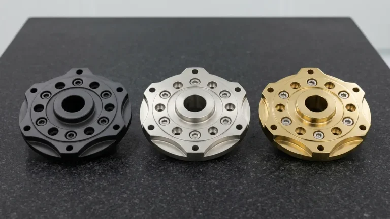
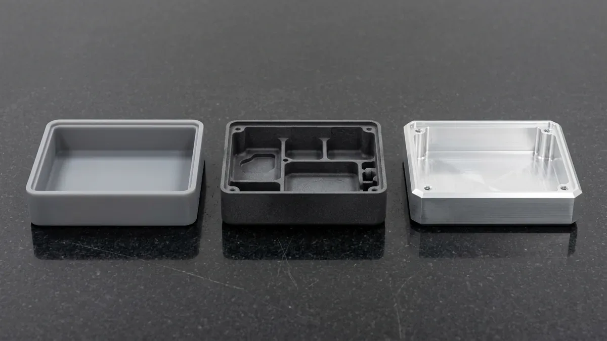
Our comprehensive manufacturing facility houses advanced factory equipment and machining centers to support every prototyping requirement. High-precision stereolithography delivers master patterns for rapid polyurethane casting. Furthermore, high-speed 3-axis, 4-axis, and 5-axis CNC machining carves functional metal prototypes directly from production-grade aerospace billets. Therefore, engineering prototypes exhibit mechanical properties identical to final production units.
4. Scaling from Pilot Runs to High-Volume Production
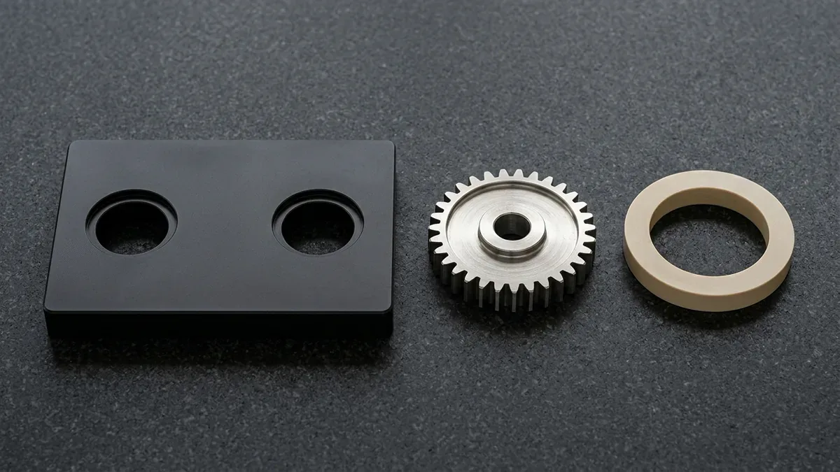
Scaling a hardware product requires disciplined supplier management and rigorous quality control protocols. Pilot production runs validate assembly line fixtures, worker cycle times, and automated test equipment. Furthermore, statistical process control monitors dimensional drift across critical-to-quality dimensions. Rigorous dimensional and material inspection protocols govern every step from raw billet verification to final protective packaging.
Experienced tooling engineers optimize injection mold gate locations and conformal cooling channels. Balanced cooling circuits accelerate injection molding cycle times without inducing internal molded stresses. In addition, automated optical metrology inspects critical dimensions to ISO 2768-mK tolerances. As a result, AS Prototypes empowers hardware innovators to transition smoothly from initial CAD sketches to millions of finished units.
The comparative characteristics of prototyping technologies across development stages are outlined in the table below.
| Prototyping Technology | Best Development Stage | Material Representation | Typical Dimensional Tolerance |
|---|---|---|---|
| SLA / PolyJet Resins | Concept Architecture & Styling | Photopolymer appearance resins | ±0.050 mm to ±0.100 mm |
| Polyurethane Vacuum Casting | Pre-Pilot User Field Trials | Simulated ABS, PC, POM, and Silicone | ±0.100 mm to ±0.150 mm |
| Precision CNC Machining | Functional Alpha & Beta Testing | Production Aluminum, Titanium, and PEEK | ±0.010 mm to ±0.025 mm |
| Rapid Aluminum Tooling | Design Verification & Pilot Runs | True production thermoplastic resins | ±0.025 mm to ±0.050 mm |
| Hardened Steel Tooling | High-Volume Mass Manufacturing | High-volume filled and unfilled plastics | ±0.010 mm to ±0.025 mm |
5. Technical Engineering FAQ
Industrial design focuses on user experience, ergonomics, aesthetic proportions, and visual brand identity. In contrast, mechanical engineering resolves internal structural integrity, thermal dissipation, material selection, and manufacturing tolerances.
A DFM review identifies un-machinable features, excessive wall thicknesses, and inadequate draft angles early. Correcting these CAD flaws prevents expensive tooling modifications, shortened tool life, and manufacturing delays later, while optimizing pocket radii and datum hierarchies for efficient 3-axis and 4-axis VMC setups.
Teams utilize rapid aluminum tooling for low-volume pilot runs to validate resin shrinkage and cycle times. Once First Article Inspection passes, hardened production molds (such as P20, H13, or S136 steel) are cut with full process confidence and verified via Zeiss CMM coordinate metrology.
Scale Your Hardware Product Design from Rapid Prototype to Mass Production
Eliminate late-stage tooling revisions, wall-thickness sink marks, and assembly stack-up risks before cutting steel. Upload your 3D CAD assemblies (STEP/IGES) and 2D drawings for a multi-process DFM review and custom prototyping or production quotation.
Upload 3D CAD for Product DFM & Scaling Quote