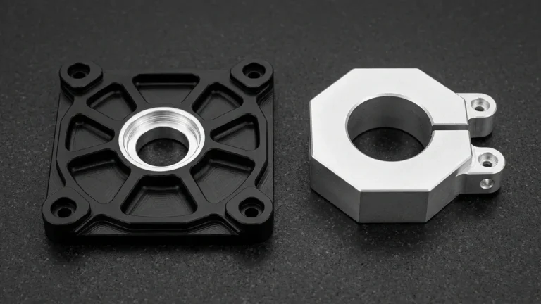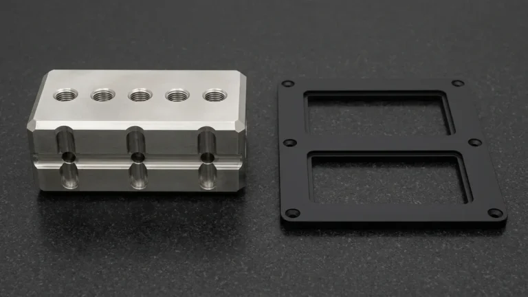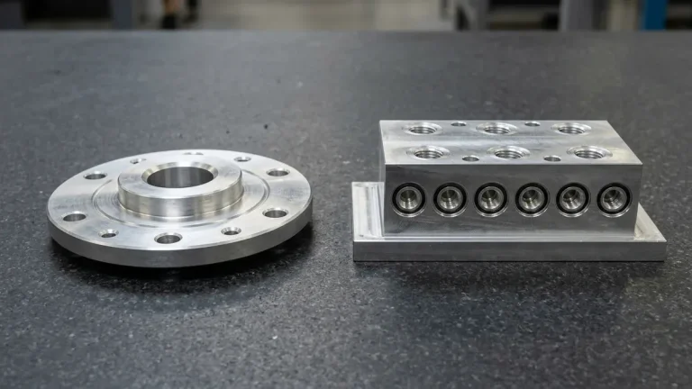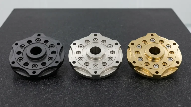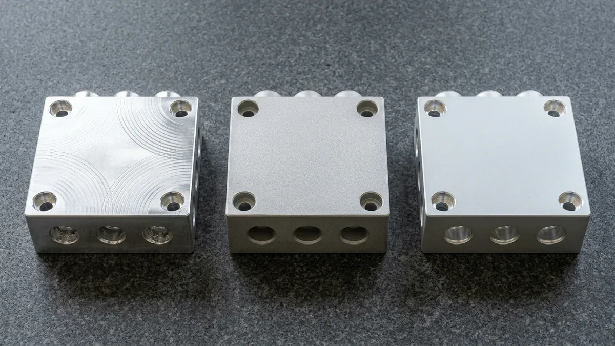
Precision CNC machined components frequently exhibit visible cutter tool marks, stepover cusps, and directional machining lines. Therefore, applying a standardized bead blasting finish provides an efficient mechanical surface treatment to eliminate visual blemishes. Bead blasting propels millions of spherical media particles at high velocity against the workpiece surface. Consequently, this impact peening action blends cutter marks, producing a uniform, non-directional satin matte appearance.
Furthermore, bead blasting induces compressive residual surface stresses that improve fatigue resistance on dynamic mechanical parts. Beyond aesthetics, the resulting micro-dimpled texture creates an ideal anchor profile for secondary anodizing and powder coating adhesion. In this comprehensive technical guide, we evaluate blasting media selections, grit mesh dimensions, pressure controls, and critical DFM rules.
Executive Summary & Engineering Takeaways (BLUF)
- Peening vs. Cutting Physics: Unlike angular aluminum oxide grit that cuts into metal and embeds sharp debris, spherical soda-lime glass and zirconia ceramic beads cold-work the surface via elastic-plastic dimpling, blending CNC toolmarks into an isotropic matte satin texture.
- Mesh Grit & Roughness Control: Coarse #60–#80 mesh (180–250 μm) removes heavy milling cusps yielding Ra 2.0–3.2 μm (80–125 μin), medium #100–#120 mesh (125–150 μm) delivers standard commercial satin at Ra 1.0–1.8 μm (40–72 μin), and fine #150–#220 mesh (63–105 μm) achieves flagship consumer electronics matte finishes of Ra 0.6–1.0 μm (24–40 μin).
- Zero-Shift Tolerance Masking: Sustained blasting can alter sharp edges and shift tight bores by 0.005 to 0.015 mm (0.0002″ to 0.0006″); all ISO H7 bearing bores (±0.010 mm / ±0.0004″), O-ring grooves, and M-series threads below M6 are protected with custom silicone plugs and Kapton masking.
- Pre-Anodize Cosmetic Synergy: Fine #120–#180 glass bead blasting followed by ultrasonic cleaning and MIL-A-8625 Type II matte black or clear anodizing eliminates directional glare and hides fingerprint smudges on optical and consumer enclosures.
Article Engineering Navigation
- 1. Fundamental Mechanics: Abrasive Cutting vs Spherical Impact Peening
- 2. Glass Bead Mesh Sizes and Surface Roughness Capabilities
- 3. Substrate Metallurgy: Aluminum, Stainless Steel, and Titanium Response
- 4. Precision Masking Strategies for Tight Tolerance Features
- 5. Cosmetic Pre-Treatment for Premium Architectural and Lighting Systems
- 6. Quantitative Hertzian Contact & Almen Peening Intensity Mechanics
- 7. Why Do Bead-Blasted Aluminum Parts Show Streaking or Cloudy Anodizing?
- 8. Step-by-Step Shop-Floor Bead Blasting & Anodizing Protocol
- 9. Technical Engineering FAQ
1. Fundamental Mechanics: Abrasive Cutting vs Spherical Impact Peening
Core Physical Principles and Shop-Floor Execution
Mechanical blasting operations divide into two distinct physical mechanisms: sharp abrasive cutting and spherical impact peening. Angular abrasive grits like aluminum oxide slice microscopically into the substrate, carving sharp micro-anchor profiles. While angular grit provides excellent mechanical tooth for thermal spray coatings, it removes substantial parent material.
Conversely, spherical glass beads and ceramic microspheres impact metal surfaces without cutting or gouging the substrate. The spherical shape peens microscopic craters into the outer grain matrix, compressing surface layers. Therefore, spherical bead blasting preserves critical dimensional tolerances on bearing lands and threads far better than angular grit. The comparative matrix below outlines core characteristics across standard industrial blasting media.
| Blasting Media Type | Chemical Composition | Particle Geometry | Mohs Hardness | Resulting Surface Finish | Media Reusability Lifespan |
|---|---|---|---|---|---|
| Soda-Lime Glass Beads | Amorphous Soda-Lime Silicate (~72% SiO2, Free-Crystalline-Silica-Free) | Spherical Microspheres | 5.5 to 6.0 | Bright satin matte, glare-free | Medium (8 to 12 cycles before fracturing) |
| Ceramic Zirconia Beads | ZrO2 (67%) / SiO2 (31%) | High-Density Spheres | 7.0 to 7.5 | Ultra-smooth satin, uniform peen | Very High (40 to 60 cycles) |
| White Aluminum Oxide | Fused Al2O3 (99.5%) | Angular Sharp Crystals | 9.0 | Rough matte, heavy micro-anchor | High (15 to 25 cycles) |
| Stainless Steel Shot | Austenitic Cr-Ni Alloy | Spherical Cast Pellets | 4.5 to 5.5 (~200–350 HV) | Semi-bright peened, heavy compressive stress | Exceptional (Hundreds of cycles) |
| Plastic Urea Media | Thermoset Polymer Compounds | Irregular Polyhedral | 3.5 to 4.0 | Gentle clean, zero substrate removal | Moderate (10 to 15 cycles) |
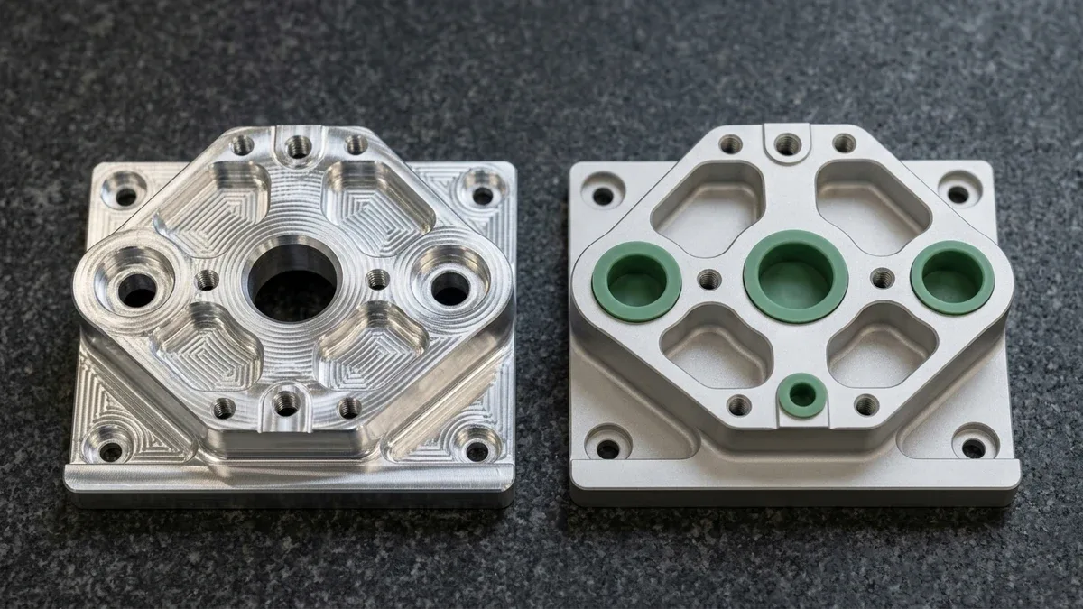
Figure 1 provides a side-by-side visual comparison between an as-machined 6061-T6 aluminum bracket exhibiting directional end-mill toolpath swirls on the left and a glass-bead-blasted bracket on the right. Silicone plugs and high-temperature masking tape protect precision-reamed bearing bores and spotfaced grounding pads during pneumatic media blasting.
2. Glass Bead Mesh Sizes and Surface Roughness Capabilities
Primary Process Capabilities and Equipment Architecture
Selecting the proper media mesh size dictates final surface roughness Ra and visual sheen. Fine glass beads produce delicate velvety textures that scatter light evenly across cosmetic consumer enclosures. Conversely, coarse beads obliterate heavy tool marks from rough machining passes, creating rugged industrial textures.
Furthermore, blast nozzle operating pressure directly modulates surface impact kinetic energy. Excessive air pressure shatters glass beads against hard metals, causing angular fragmentation and inconsistent surface mottling. Therefore, maintaining forty to sixty psi pressure preserves media spherical integrity. The technical table below correlates standard mesh numbers with resulting Ra values on aluminum 6061-T6.
| Glass Bead US Mesh Size | Nominal Particle Diameter (µm) | Resulting Ra on 6061-T6 (µm) | Visual Surface Texture | Primary Production Domain |
|---|---|---|---|---|
| US Mesh #30–#40 (Coarse) | 425 to 850 µm | 2.8 to 4.5 µm (110 to 180 µin) | Coarse textured matte | Heavy weld blending, casting de-burring, structural frames |
| US Mesh #60–#80 (Medium-Coarse) | 180 to 250 µm | 1.6 to 2.8 µm (63 to 110 µin) | Balanced satin finish | Industrial equipment panels, automotive brackets, tooling plates |
| US Mesh #100–#120 (Shop Standard Satin) | 125 to 150 µm | 0.8 to 1.6 µm (32 to 63 µin) | Fine velvet matte | Consumer electronics, optical housings, pre-anodizing baseline |
| US Mesh #150–#220 (Fine Velvet Matte) | 63 to 105 µm | 0.4 to 0.8 µm (16 to 32 µin) | Semi-reflective micro-matte | Medical surgical tools, precision dental handpieces, delicate dials |
3. Substrate Metallurgy: Aluminum, Stainless Steel, and Titanium Response
Critical Process Parameters and Tooling Selection
Different engineering alloys react uniquely to blast media impact depending on inherent material hardness. Soft wrought aluminum alloys, such as 6061-T6 and 5052-H32, dimple easily under low impact pressures. Consequently, operators must move blast nozzles continuously to avoid localized wall thinning or surface wavy distortion.
In contrast, austenitic stainless steel 304 and 316 work-harden rapidly during mechanical blasting. This surface peening enhances resistance to stress corrosion cracking in aggressive marine and chemical environments. Furthermore, titanium alloys achieve remarkable glare reduction under fine glass bead blasting, critical for tactical aerospace housings. Reviewing material hardness ensures optimized nozzle standoffs and blasting angles.
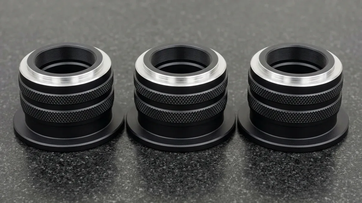
As shown in Figure 2, combining fine glass-bead blasting with MIL-A-8625 Type II matte black anodizing produces a uniform, low-reflectance satin finish across three CNC-turned 7075-T6 aluminum optical lens barrels. Post-machined silver datum shoulders preserve micron-level optical seating accuracy while internal surfaces suppress stray light reflection.
4. Precision Masking Strategies for Tight Tolerance Features
Practical Design-for-Manufacturing (DFM) Guidelines
Because bead blasting impacts exposed surfaces aggressively, critical features must be protected using precision masking. Dowel pin bores, bearing journals, and ground mating faces cannot tolerate dimensional alterations. Specifically, high-elasticity silicone plugs and custom vinyl masking dots shield precision tolerances reliably.
Furthermore, internal threaded holes below M6 size must be plugged to prevent abrasive grit entrapment. Residual trapped glass powder causes severe thread galling and fastener seizure during final assembly. Technicians apply automated ultrasonic cleaning cycles following blasting to purge all microscopic media residues. Explore our range of precision surface finishing capabilities to configure your ideal post-treatment pipeline.
5. Cosmetic Pre-Treatment for Premium Architectural and Lighting Systems
In architectural lighting and consumer hardware, bead blasting serves as the mandatory pre-treatment before decorative anodizing. Raw extruded or milled aluminum reflects light specularly, highlighting minor metallurgical grain boundaries. Blasting converts directional reflections into diffuse isotropic scatter, providing a luxurious velvety feel.
Moreover, combining fine bead blasting with color dye anodizing delivers deep, consistent color saturation across large surface panels. Discover how our engineering team manufactures custom architectural enclosures for commercial lighting and optical hardware worldwide.
6. Quantitative Hertzian Contact & Almen Peening Intensity Mechanics
Dynamic Hertzian Elastic-Plastic Indentation Scaling
Achieving a repeatable cosmetic matte texture across production batches requires controlling the kinetic energy transfer of each spherical bead impact. Unlike manual cabinet blasting where operator nozzle movement varies wildly, automated indexing blast cells regulate air line pressure, media mass flow rate, nozzle standoff distance, and impingement angle through quantitative contact mechanics.
When a spherical soda-lime glass or zirconia ceramic bead of diameter dp and density ρp strikes a metallic substrate of Vickers hardness Hv at normal impact velocity vn = v · sin(θ), the resulting microscopic plastic dimple diameter di and peak indentation depth hp follow dynamic Hertzian elastic-plastic impact scaling:
hp ≈ 0.28 · dp · [ (ρp · v2 · sin2θ) / Hv ]1/2 | Rafinal ≈ 0.18 · hp + Csub
6061-T6 Aluminum vs. 316L Stainless Steel Peening Depth Comparison
where Csub ≈ 0.5–0.8 μm represents the residual baseline substrate texture after cusp flattening.
Consider a shop-floor calculation comparing 6061-T6 aluminum (95 HB / ~107 HV, Hv ≈ 1.05 GPa) against annealed 316L stainless steel (~155 HV, Hv ≈ 1.52 GPa) blasted with #120 mesh glass beads (mean diameter dp = 125 μm / 0.0049″, density ρp = 2,500 kg/m³) at a nozzle pressure of 4.0 bar (58 psi, particle velocity v ≈ 65 m/s) and a 75° impingement angle (sin²(75°) = 0.933):
- 6061-T6 Aluminum Indentation Depth: The dimensionless energy ratio equals (2,500 × 65² × 0.933) / (1.05 × 10⁹) = 0.00938, yielding a square root of 0.0968 and a crater depth of hp ≈ 0.28 × 125 × 0.0968 = 3.39 μm (133 μin), producing an arithmetic average roughness of Ra 1.1 to 1.4 μm (44 to 55 μin).
- 316L Stainless Steel Indentation Depth: Under the exact same 4.0 bar air pressure, the higher yield resistance (1.52 GPa) reduces crater depth to hp ≈ 2.81 μm (110 μin) and shifts rapidly toward strain hardening, requiring either 5.0 to 5.5 bar (72 to 80 psi) pressure or higher-density zirconia ceramic beads (ρp = 3,850 kg/m³) to achieve equivalent cusp blending.
- Thin-Wall Almen Arc Height Deflection: Because spherical peening stretches the top 25 to 75 μm (0.001″ to 0.003″) of metal plastically, blasting only one side of a thin aluminum cover plate (<1.5 mm / 0.060″ thick) induces a convex bow of 0.15 to 0.60 mm per 100 mm span. Balanced dual-side blasting at reduced pressure (2.2 to 2.8 bar / 32 to 40 psi) is mandatory for thin enclosures.
7. Why Do Bead-Blasted Aluminum Parts Show Streaking or Cloudy Anodizing?
Cyclone Media Classification and Ultrasonic Desmutting Controls
Streaking, blotchy dark clouds, and uneven specular reflection on bead-blasted and anodized aluminum housings are caused by fractured angular glass dust breakdown, oil contamination inside recirculating cyclone media hoppers, or excessive nozzle dwell heat during blasting. While fresh spherical beads create uniform isotropic micro-dimples, shattered glass fragments gouge directional micro-scratches that trap acid and organic dye unevenly during MIL-A-8625 Type II anodizing.
To prevent cosmetic rejection across multi-piece assembly enclosures, our finishing shop enforces strict cyclone separator classification, media replenishment schedules, and post-blast ultrasonic nitric-acid desmutting before racking parts into the anodizing tank.
| Surface Defect / Symptom | Physical / Chemical Root Cause | Critical Process Threshold | Shop-Floor Corrective Action | Inspection / Verification |
|---|---|---|---|---|
| Tiger Striping / Directional Banding | Nozzle held too close (<100 mm) or uneven manual sweep overlap across wide flat plates | Standoff distance <120 mm (4.7″) or nozzle wear >1.5 mm | Maintain 150–220 mm (6″–8.5″) standoff at 60°–75° angle with 50% cross-hatch pass overlap | 60° glossmeter check (≤2 GU variation) under D65 light booth |
| Dark Smut & Embedded Silica Staining | Over-pressurized glass beads (>5.5 bar) shattering on impact and imbedding into soft 6061 aluminum | Broken media fraction >15% in hopper cyclone | Cap aluminum air pressure at 3.0–4.2 bar (45–60 psi); tune cyclone air-wash to purge dust <45 μm | 20× optical stereo microscopy & post-blast acid etch test |
| Galvanic Rust Spots on Stainless / Aluminum | Cross-contamination from blasting aluminum or 316L in a cabinet previously used for carbon steel | Free iron contamination >0.01% in blast media | Segregate dedicated “Non-Ferrous & Stainless Only” blast cabinets; passivate per ASTM A967 | Copper sulfate (CuSO4) free-iron test & 48h humidity chamber |
| Rolled Edge Burrs in Precision Bores | Direct media stream peening unmasked H7 bearing bores or fine M2–M4 internal threads | Bore diameter shift >0.008 mm (0.0003″) | Insert tapered EPDM/silicone expansion bungs and high-tack die-cut Kapton discs prior to blasting | ISO 286 Go/No-Go cylindrical plug gauge & thread plug check |
| Visible CNC Tool Stepover Lines After Blast | As-machined milling cusps exceed Ra 3.2 μm (125 μin) before fine #180/#220 bead blasting | Pre-blast cusp height Rz >15 μm (600 μin) | Machine cosmetic A-surfaces to Ra ≤0.8–1.6 μm (32–63 μin) or run dual-stage (#100 then #180) blast | Contact stylus profilometer per ISO 4287 / ASME B46.1 |
Engineering Trade-Offs: When NOT to Specify Bead Blasting
While spherical media blasting is the gold standard for satin cosmetic hardware, engineers must avoid applying bead blasting across four specific functional zones:
- Dynamic Elastomer O-Ring & Lip-Seal Grooves: Isotropic micro-dimples create interconnected capillary leak paths under high-vacuum or high-pressure hydraulic O-rings; seal glands must remain as-machined or polished to directional concentric lay at Ra 0.4–0.8 μm (16–32 μin).
- High-Frequency RF Waveguide Interiors (Above 20 GHz): At millimeter-wave frequencies, electromagnetic skin depth shrinks to 0.4–0.8 μm; increasing surface roughness from Ra 0.4 μm to Ra 1.8 μm via bead blasting dramatically increases conductor insertion loss and phase noise.
- Ultra-Thin Diaphragms & Flexure Hinges (<0.8 mm / 0.031″): Peening-induced compressive surface stress permanently alters the spring rate and zero-point calibration of metallic load-cell flexures and pressure sensor membranes.
- Unmasked Precision Bearing Journals & Sliding Guideways: Even minimal spherical media impingement alters ISO h6/g6 interference and sliding fits and embeds microscopic silicate residue into lubricated ways; always mask bearing seats with custom silicone bungs.
8. Step-by-Step Shop-Floor Bead Blasting & Anodizing Protocol
Five-Stage Surface Preparation and Anodizing Integration
To ensure consistent satin reflectivity and zero dimensional drift from prototype to 1,000-unit production batches, AS Prototypes executes a five-stage surface preparation workflow:
- Pre-Blast Ultrasonic Degreasing & Deburring — Machined components undergo aqueous ultrasonic cleaning at 60°C (140°F) to strip water-soluble CNC coolant emulsions and cutting oils so hydrocarbons never contaminate the dry glass/ceramic media hopper.
- Precision Silicone & Kapton Masking — Operators install reusable high-durometer silicone pull-plugs into all threaded holes (M1.6–M12), press-fit dowel bores (±0.010 mm / ±0.0004″), and apply die-cut polyimide tape over datum pads.
- Controlled-Pressure Spherical Peening — Parts are blasted inside dedicated alloy-segregated cabinets at 3.0 to 4.2 bar (45 to 60 psi) using cyclone-classified #120, #150, or #180 glass or zirconia beads at a 150–200 mm (6″–8″) standoff and 65°–75° angle.
- Dry Nitrogen Blow-Off & Ultrasonic Rinse — Immediately after unmasking, parts are purged with ionized dry compressed air and agitated in deionized (DI) water ultrasonic baths to dislodge any electrostatic dust trapped inside blind pockets.
- Stylus Profilometry & Immediate Conversion Coating — Quality inspectors verify arithmetic roughness (Ra and Rz per ISO 4287) across three orthogonal orientations before transferring parts directly to MIL-A-8625 anodizing or ASTM A967 passivation within 4 hours.
🔗 Related Surface Finishing, Anodizing & Roughness Guides
9. Technical Engineering FAQ
Spherical glass beads cold-peen metal surfaces to a uniform satin finish of Ra 0.6–1.8 µm, whereas angular oxide grit shears microscopic chips. Specify #120–#180 glass beads prior to cosmetic MIL-A-8625 anodizing, and reserve angular aluminum oxide (Ra 2.5–6.3 µm) to anchor thick powder coatings.
Controlled glass bead blasting at 3.0–4.5 bar with unbroken #120–#180 media removes less than 0.002–0.005 mm of substrate material. However, because peening impact can roll microscopic edge burrs, always call out protective masking on 2D drawings for ±0.010 mm bores and threads.
Abrasive media stripping removes the native oxide barrier and increases effective surface area by 30%–50%, leaving bare metal highly reactive to moisture and oils. Our shop routes blasted aluminum into MIL-A-8625 anodizing within 4–6 hours and passivates stainless steel per ASTM A967.
Sintered zirconia ceramic beads (700–800 HV) last 60–100+ impact cycles without shattering, whereas soda-lime glass beads (515 HV) fracture after 6–10 impacts. Specify ceramic media on 17-4PH stainless steel and Ti-6Al-4V titanium batches to maintain uniform Ra texture and prevent silica contamination.
Ready to Validate Your CAD Design for Precision Manufacturing?
Upload your 3D CAD models (STEP, IGES, SolidWorks) and 2D engineering drawings for a comprehensive DFM engineering review and custom quotation from our in-house CNC machining and prototyping team.
Request a Custom DFM Review & Quote →