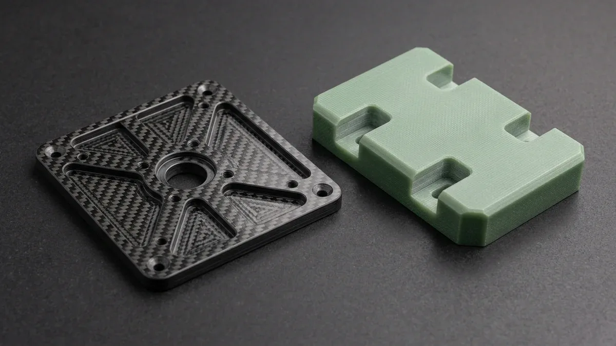
Modern aerospace structures, racing chassis, and medical equipment rely heavily on advanced fiber-reinforced polymer composites. Therefore, mastering an engineering composite machining guide helps manufacturing teams eliminate delamination, fiber pullout, and rapid tool wear. Unlike homogeneous metals that yield ductile cutting chips, fiber composites are inhomogeneous and anisotropic. Consequently, cutting tools fracture brittle reinforcing fibers while shearing viscoelastic polymer matrices simultaneously.
Furthermore, carbon and glass fibers are intensely abrasive, degrading standard carbide cutters rapidly. In this technical guide, we analyze cutting mechanics, polycrystalline diamond (PCD) tooling strategies, and thermal heat management. In shop-floor practice, we provide crucial DFM guidelines to ensure clean edge quality across multi-ply laminates.
Executive Summary & Engineering Takeaways (BLUF)
- Anisotropic Fiber-Matrix Shearing: Unlike homogeneous metals that shear via plastic chip flow, Carbon Fiber Reinforced Polymers (CFRP) and Glass Fiber Epoxy (G10/FR4) fracture via brittle fiber shearing and resin cleavage, making interlaminar peel-up and push-out delamination the primary failure mode.
- PCD Diamond & CVD Compression Cutters: Abrasive carbon and glass fibers strip standard uncoated carbide edges within meters of cut path; production composite trimming mandates Polycrystalline Diamond (PCD) or CVD diamond-coated dual-helix compression routers that direct cutting forces inward toward the laminate mid-plane.
- Critical Thrust Force Threshold (Fcrit): Preventing exit ply push-out during hole making requires keeping axial thrust force below Hocheng-Dharan’s critical delamination limit via helical orbital bore milling or dagger/brad-point diamond drills backed by sacrificial phenolic support plates.
- Glass Transition (Tg) & Dry HEPA Extraction: Because epoxy matrices soften and smear above their glass transition temperature (Tg ≈ 120°C–180°C / 248°F–356°F) and absorb liquid coolants via capillary wicking, composite machining utilizes chilled vortex air jets paired with HEPA vacuum dust extraction.
Article Engineering Navigation
- 1. Composite Material Classes: CFRP, GFRP, and Aramid Mechanics
- 2. Tooling Geometry: The Power of Dual-Helix PCD Compression Cutters
- 3. Thermal Management: High-Velocity Dust Extraction and Cold Air Jets
- 4. Precision DFM Guidelines for Composite Machining
- 5. Quantitative Delamination Thrust Physics, Fiber Cutting Angle & PCD Tool Wear
- 6. How Do You Prevent Delamination, Uncut Fiber Fuzz, and Thermal Resin Smearing?
- 7. When NOT to Machine Composites from Flat Plate & Composite DFM Checklist
- 8. Technical Engineering FAQ
1. Composite Material Classes: CFRP, GFRP, and Aramid Mechanics
Core Physical Principles and Shop-Floor Execution
Each composite reinforcement presents unique abrasive wear and fiber shearing challenges. For example, carbon fiber reinforced polymer (CFRP) provides exceptional stiffness but exhibits extreme abrasiveness against cutting edges. Conversely, glass fiber reinforced polymer (GFRP) causes heavy mechanical abrasion and generates fine silica dust.
Meanwhile, aramid or Kevlar fibers possess extreme tensile toughness. Instead of fracturing cleanly, aramid fibers bend away from cutting flutes, creating fuzzy frayed edges. The engineering table below contrasts machining characteristics across standard composite families.
| Composite Laminate Type | Reinforcement Fiber | Tool Wear Severity | Primary Defect Risk | Recommended Tooling Substrate |
|---|---|---|---|---|
| Aerospace CFRP | High-modulus carbon fibers | Extreme (Abrasive flank wear) | Top-ply peeling & exit delamination | Polycrystalline Diamond (PCD) / Diamond-coated |
| Structural GFRP | E-glass / S-glass fibers | Very High (Silica abrasion) | Matrix scorching & edge chipping | CVD diamond-coated solid carbide |
| Ballistic Aramid (Kevlar) | Para-aramid synthetic fibers | Moderate | Severe fiber fuzzing & uncut fibers | High-shear serrated scissor-flute PCD |
| Carbon/Glass Hybrid | Interleaved carbon & glass plies | Extreme | Interlaminar shear delamination | Dual-helix compression PCD router bits |
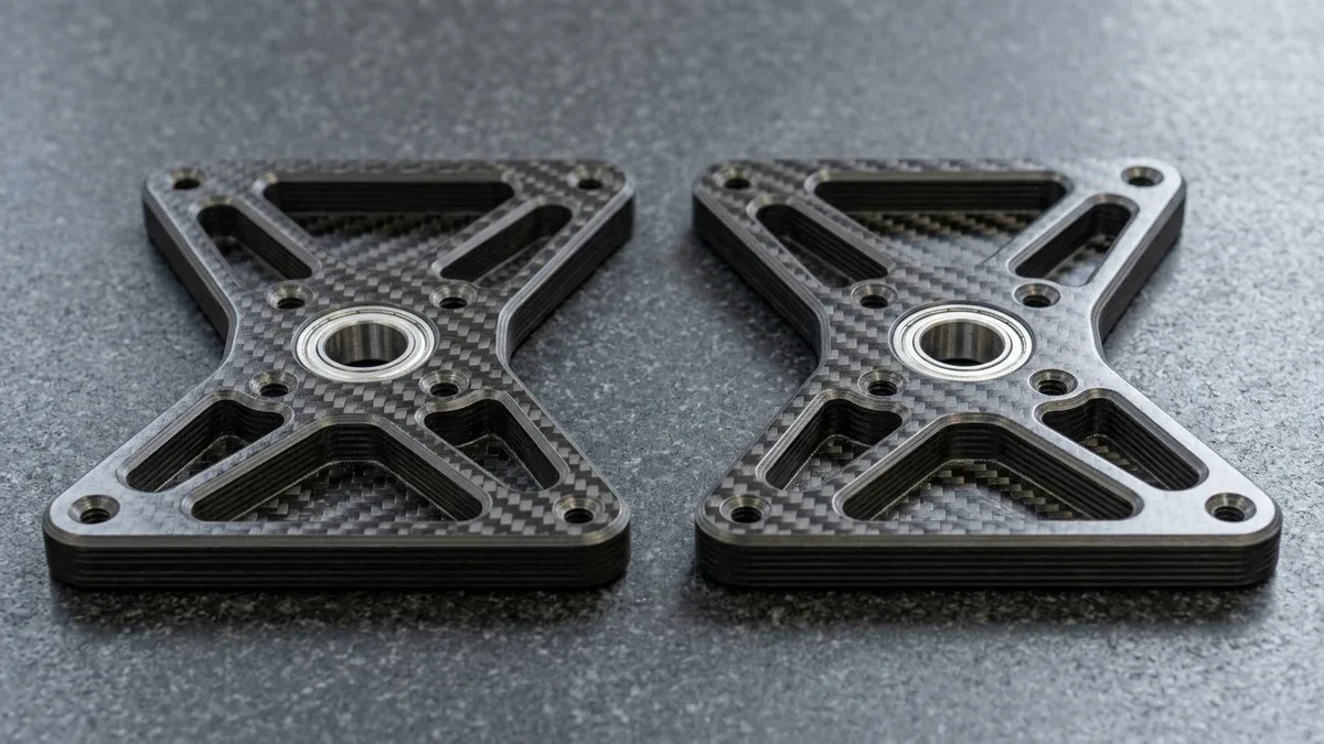
As shown in Figure 1, a pair of CNC-machined 4.0 mm quasi-isotropic twill-weave CFRP carbon fiber drone motor arm brackets rest flat on black granite, exhibiting delamination-free pocket walls and pressed-in metallic bearings. Polycrystalline diamond (PCD) compression tooling shears carbon fibers cleanly without fraying top or bottom plies.
2. Tooling Geometry: The Power of Dual-Helix PCD Compression Cutters
Primary Process Capabilities and Equipment Architecture
Standard up-cut spiral end mills exert upward lifting forces that peel top laminate plies away. Conversely, down-cut spiral tools push downward, triggering bottom-ply delamination breakout. Therefore, machining structural composites requires dual-helix compression router bits.
Specifically, a compression cutter combines up-cut flutes at the tool bottom with down-cut flutes at the top. When engaged at proper depths, both opposing cutting forces compress plies inward toward the laminate center. As a result, both top and bottom laminate surfaces achieve pristine, burr-free edges. Explore our precision CNC milling services to configure automated composite trimming operations.
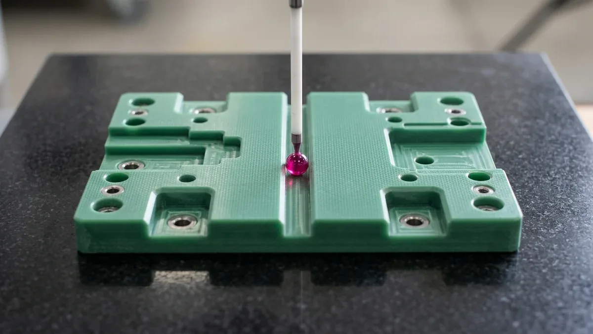
In Figure 2, a vertical CMM ruby ball stylus verifies slot width and hole position tolerances on a CNC-machined green G10/FR4 woven glass-epoxy electrical insulation terminal plate on black granite. Dry chilled-air cooling and HEPA dust extraction preserve resin dielectric integrity during high-speed abrasive composite routing.
3. Thermal Management: High-Velocity Dust Extraction and Cold Air Jets
Critical Process Parameters and Tooling Selection
Traditional flood liquid coolant presents severe risks during composite machining. Moisture absorption causes resin matrix swelling, while wet carbon sludge complicates hazardous waste disposal. Consequently, dry machining with high-velocity vacuum extraction represents the industry gold standard.
Furthermore, targeted vortex tube cold air jets cool cutting zones without introducing liquid contaminants. Cold air suppresses cutting friction temperatures below the matrix glass transition threshold (Tg). Preventing thermal matrix softening prevents resin smearing and fiber pullout. In addition, our manufacturing facility fabricates lightweight structural housings and brackets for aerospace and unmanned aerial vehicles.
4. Precision DFM Guidelines for Composite Machining
Practical Design-for-Manufacturing (DFM) Guidelines
Designing composite components with machining in mind prevents catastrophic delamination during manufacturing. First, incorporate sacrificial top and bottom surface plies on critical structural panels. Sacrificial scrim plies absorb any minor surface peeling during high-speed routing.
Second, when drilling fastener clearance holes, utilize orbital helical milling rather than standard twist drilling. Helical interpolation reduces axial thrust forces by up to 60 percent, eliminating push-out exit delamination entirely. Finally, maintain minimum edge distances of at least three times the hole diameter to prevent edge blowout.
5. Quantitative Delamination Thrust Physics, Fiber Cutting Angle & PCD Tool Wear
Hocheng-Dharan Critical Axial Thrust Force for Delamination-Free Drilling
When drilling laminated Carbon Fiber Reinforced Polymer (CFRP), Glass Fiber (GFRP), or FR4/G10 epoxy boards, exit push-out delamination occurs when the drill’s axial thrust force (Fz) exceeds the interlaminar Mode I fracture toughness (GIC) of the remaining uncut epoxy plies. Unlike isotropic metals that yield plastically, laminated composites fracture along ply boundaries when axial thrust bends the last 1–2 plies downward.
• Critical Delamination Thrust (Hocheng-Dharan): FA,crit = π × √[ (8 × GIC × E × h³) / (3 × (1 − ν²)) ] [N]
• Delamination Factor Ratio: Fd = Dmax,delam / Dnominal (Aerospace & structural target: Fd ≤ 1.05)
• Matrix Thermal Limit: Tcut < Tg,epoxy − 25°C (Keep cutting zone below 120°C–150°C to prevent resin smearing)
Fiber Orientation Angle (0° / 45° / 90° / 135°) Fracture Modes
During peripheral CNC contour routing of unidirectional or woven prepreg laminates, the instantaneous cutting mechanism shifts every 45° around the cutter path. At 0° and 45° fiber orientation, the cutting edge shears fibers cleanly under compression; however, at 135° (cutting against the fiber lay), the flute lifts fibers upward in bending, triggering subsurface micro-cracking and severe edge fuzzing unless up/down compression routers are deployed.
Polycrystalline Diamond (PCD) vs. CVD Diamond-Coated Compression End Mills
Carbon and E-glass fibers are highly abrasive, stripping standard TiAlN-coated carbide cutting edges dull within 1.5–3.0 linear meters (5–10 ft) of routing and multiplying axial thrust force threefold. Switching to nano-crystalline CVD diamond-coated compression routers (which combine upward-pulling lower flutes with downward-pushing upper flutes) or brazed PCD tooling extends tool life 15× to 25× while keeping cut edges burr-free.
6. How Do You Prevent Delamination, Uncut Fiber Fuzz, and Thermal Resin Smearing?
Controlling Breakthrough Feed Rate and Sacrificial Backing Plates
Because uncut laminate thickness (h) drops toward zero as a drill approaches exit breakthrough, critical thrust force FA,crit scales down with h3/2. To prevent exit ply blowout on quasi-isotropic CFRP plates, CNC programs step down axial feed rate from 0.05 mm/rev (0.002 in/rev) to 0.012 mm/rev (0.0005 in/rev) over the final 1.0 mm of travel, or clamp the laminate tightly against a sacrificial phenolic/aluminum backing board.
| Observed Defect / Symptom | Physical Root Cause | Quantitative Process Threshold | Corrective Shop-Floor Action | Inspection Verification Method |
|---|---|---|---|---|
| Peel-up delamination at hole entry or top perimeter edge | Positive helix flute pulling top woven ply upward before shearing | Helix angle > 25° upward without top sacrificial cap or compression flute | Switch to left-hand down-cut or dual-helix compression diamond router so top plies stay under downward compression | Optical stereo microscope and delamination factor measurement (Fd ≤ 1.05) |
| Push-out delamination and spalling at drill exit | Axial chisel-edge thrust exceeding interlaminar resin fracture toughness GIC | Thrust force Fz > 60–90 N during final 0.5 mm breakthrough | Use 8-facet split-point or brad-point CVD diamond drill, reduce exit feed by 70%, or orbital-mill the bore | Ultrasonic C-scan NDT or backlit optical bore inspection |
| Gummy resin smearing and burnt black matrix edges | Frictional rubbing from worn cutter flank exceeding epoxy glass transition Tg | Cutting temperature Tcut > 160°C or feed per tooth fz < 0.015 mm/tooth | Maintain minimum chip load fz = 0.03–0.06 mm/tooth, retire tools at VB = 0.05 mm wear, and apply chilled air vortex | Differential scanning calorimetry check and 50× edge cross-section audit |
| Uncut fuzzy fiber fraying on Aramid (Kevlar) or hybrid edges | High tensile ductility of aramid fibers bending away from standard cutting edges | Cutting edge hone radius re > 10 μm failing to shear ductile fibers | Use razor-sharp uncoated micro-grain carbide compression shears with opposing shearing flutes at 18,000+ RPM | Tactile pin-gauge check and CMM optical vision profile scan |
Orbital Helical Bore Milling vs. Direct Axial Drilling
For high-value carbon-fiber drone frames, medical radiolucent imaging plates, and robotics links with bores ≥ Ø6.0 mm (0.236 in), helical orbital milling with a smaller-diameter diamond end mill eliminates central chisel-edge thrust entirely. Directing cutting forces radially rather than axially reduces axial delamination thrust by 60% to 80% and vents abrasive carbon dust effortlessly through the central clearance gap.
7. When NOT to Machine Composites from Flat Plate & Composite DFM Checklist
When NOT to Specify Subtractively Machined Laminated Plate
Hardware engineers should avoid machining 3D contours directly out of flat laminated CFRP or GFRP sheet stock in three structural scenarios:
- Deep 3D Pockets That Sever Load-Bearing Continuous Fibers: Milling deep pockets or steps across structural carbon-fiber plates cuts through continuous tension plies, reducing flexural strength by up to 60% and exposing interlaminar edges to moisture ingress; use molded prepreg layups instead.
- Direct Tapped Threads in Thin Laminate Edges (< 6.0 mm / 0.24 in): Cutting threads parallel to composite plies wedges the layers apart under bolt torque; always specify bonded/potted 303 stainless or titanium threaded inserts.
- Oil-Lubricated Flood Coolant Machining on Open-Weave Laminates: Porous composite edges absorb water-soluble and oil coolants by capillary action, ruining subsequent structural epoxy bonding; specify dry machining with HEPA negative-pressure vacuum extraction or pure chilled air blast.
Four-Step Composite CNC Machining DFM Verification Protocol
- Select Quasi-Isotropic Layups With Woven Outer Plies: Specify a 0°/90° twill or plain-weave carbon/glass fabric as the top and bottom skin plies over unidirectional cores to lock surface fibers against entry/exit fraying.
- Maintain Minimum Hole-to-Edge Distance ≥ 2.5×D to 3.0×D: Keep all fastener bores at least 2.5 to 3.0 times hole diameter away from trimmed laminate edges to prevent shear tear-out and interlaminar edge splitting.
- Replace Cut Threads With Bonded Metal Stand-Offs or Rivet Bushings: Design counterbored clearance holes for mechanical flanged bushings or epoxy-potted inserts rather than tapping directly into resin-matrix composites.
- Specify Dry Chilled-Air Cutting and HEPA Dust Extraction: Add a drawing note requiring coolant-free dry machining (or deionized mist where permitted) so machined parts remain 100% clean for secondary structural adhesive bonding.
🔗 Related Aerospace, Drone & High-Speed CNC Milling Guides
8. Technical Engineering FAQ
CVD diamond coatings (8,000–9,000 HV) and brazed PCD cutters extend tool life by 10×–25× over standard carbide, which dulls within 2–5 linear meters. Our machine shop mandates sharp diamond edges to shear carbon and glass fibers cleanly without triggering interlaminar ply delamination.
Dual-helix compression routers combine 15°–30° up-cut bottom flutes with down-cut upper flutes to direct axial forces inward, preventing outer ply fraying and delamination. For full-depth profiling of 2.0–15.0 mm CFRP laminates, program axial engagement so the flute transition sits below the top ply.
Helical orbital interpolation directs 85% of cutting loads radially along the strong fiber plane, eliminating the high axial thrust that causes twist-drill exit blowout. Programming a spiral path with diamond end mills holds ±0.025 mm hole tolerances while continuously venting heat and composite dust.
Water-based emulsion coolants must be avoided because capillary moisture absorption degrades G10/FR4 dielectric breakdown strength and contaminates CFRP surfaces before structural epoxy bonding. Our shop mandates dry machining with –10°C chilled vortex air and HEPA vacuum extraction to prevent conductive carbon sludge.
Ready to Validate Your CAD Design for Precision Manufacturing?
Upload your 3D CAD models (STEP, IGES, SolidWorks) and 2D engineering drawings for a comprehensive DFM engineering review and custom quotation from our in-house CNC machining and prototyping team.
Request a Custom DFM Review & Quote →