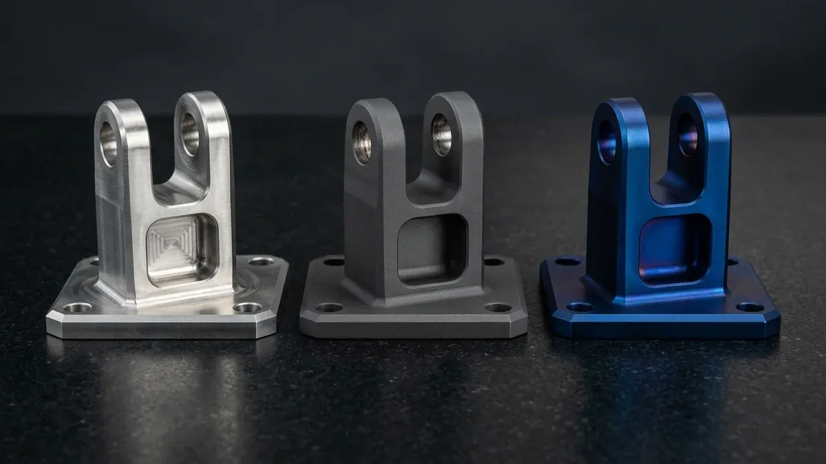
In mission-critical orthopedic implants, flight-control actuators, and subsea instrumentation, titanium anodizing serves as an essential electrochemical surface engineering process. Unlike aluminum anodizing, which grows a thick porous oxide that must be dyed and hydrothermally sealed, titanium anodizing converts the outer substrate into a dense, chemically inert titanium dioxide (TiO2) ceramic barrier.
Depending on electrolyte chemistry and direct-current (DC) voltage regulation between 10 V and 110 V, this process delivers either a 1.0 µm to 2.5 µm (0.04 to 0.10 thou) anti-galling conversion layer per AMS 2488 Type II or a 15 nm to 150 nm (0.59 to 5.91 µin) Type III optical interference color film.
At our Shenzhen CNC machining and surface finishing facility, our in-house engineering team integrates high-speed 3-axis, 4-axis, and Swiss-type titanium machining with voltage-regulated anodizing lines. This guide details thin-film interference physics, nitric-hydrofluoric (HNO3/HF) pickling protocols, and actionable Design for Manufacturing (DFM) rules for Ti-6Al-4V (Grade 5), Grade 23 ELI, and CP Grade 2 hardware.
Executive Summary & Engineering Takeaways (BLUF)
- Zero-Dye Optical Interference Physics (Type III / ASTM F86): Acid-electrolyte color anodizing grows a transparent 15 nm to 150 nm (0.59 to 5.91 µin) TiO2 barrier film at αanod ≈ 1.6 to 2.0 nm/V (0.063 to 0.079 µin/V), creating repeatable bronze, blue, gold, purple, and green hues without organic dyes or dimensional build-up on ±0.010 mm (±0.0004 in) features.
- AMS 2488 Type II Anti-Galling Protection: High-voltage alkaline baths (pH > 13) produce a dense 1.0 µm to 2.5 µm (0.04 to 0.10 thou) matte dark-gray conversion layer that eliminates titanium-on-titanium cold welding (galling) and insulates carbon-fiber (CFRP) airframe joints against galvanic corrosion.
- Alloy Composition Voltage Shift: Dual-phase alpha-beta Ti-6Al-4V (Grade 5 and Grade 23 ELI) requires +3 V to +8 V higher DC potential than commercially pure CP Grade 2 titanium to achieve equivalent interference colors due to vanadium-rich beta-phase partitioning.
- Controlled 10:1 HNO3/HF Pickling Chemistry: Pre-anodizing chemical etching in 15%–25% HNO3 + 1.5%–2.5% HF by volume (maintaining a strict 10:1 nitric-to-hydrofluoric volumetric ratio at 20°C–30°C / 68°F–86°F) strips native mill oxides and iron tool transfer while keeping hydrogen absorption below 125–150 ppm.
- Predictable Turnaround Separation: Our ex-factory production and inspection turnaround is 7–12 business days for CNC-machined and anodized titanium prototypes (7–30 business days for low-to-mid volume batches), tracked separately from 3–5 business days international express air transit.
Article Engineering Navigation
- 1. Fundamental Physics: TiO₂ vs Al₂O₃ Anodizing
- 2. Thin-Film Interference Equations & Voltage Spectrum
- 3. AMS 2488 Type II vs Type III Specifications
- 4. Pre-Treatment Chemistry & HNO₃/HF Pickling SOP
- 5. Surface Roughness (Ra), Racking & Tolerance DFM
- 6. Process Limitations, Fatigue & Defect Matrix
- 7. Metrology Protocols & Ex-Factory Lead Times
- 8. Technical Engineering FAQ
1. Fundamental Physics: Titanium TiO₂ Barrier Growth vs Aluminum Al₂O₃ Anodizing
Mechanical engineers transitioning from aluminum hardware to titanium components frequently assume both metals share identical anodizing mechanisms. In reality, precision anodizing operates via two fundamentally different electrochemical growth modes on aluminum versus titanium substrates. Understanding this electrochemical distinction prevents costly drawing callout errors on tight-tolerance medical and aerospace assemblies.
In sulfuric or chromic acid aluminum anodizing (MIL-A-8625 Type II and Type III), acid dissolution competes with oxide growth to form a porous aluminum oxide (Al2O3) structure measuring 5 µm to 75 µm (0.20 to 2.95 thou). Because half of that layer grows outward, engineers must compensate for dimensional build-up on threads and bores.
Furthermore, aluminum anodizing achieves colors by immersing the open porous Al2O3 honeycomb into heated organic dye tanks or inorganic metal salt baths, followed by a boiling deionized water or nickel-acetate hydrothermal seal. Those organic dyes can leach under autoclave sterilization or degrade under prolonged ultraviolet radiation in orbital and marine environments.
Conversely, standard color titanium anodizing (AMS 2488 Type III / ASTM F86) grows a dense, non-porous, dielectric barrier layer of crystalline anatase titanium dioxide (TiO2). When a titanium workpiece serves as the anode in a dilute phosphoric acid, sulfuric acid, or ammonium phosphate bath, applied DC voltage drives oxygen anions (O2−) inward.
Simultaneously, titanium cations (Ti4+) migrate outward across the oxide lattice to react at the electrolyte interface via Ti + 2H2O → TiO2 + 4H+ + 4e−. Because the TiO2 barrier is electrically insulating, ionic transport stops automatically once oxide thickness balances the applied electric field (~5 × 10⁶ V/cm).
Consequently, titanium barrier anodizing is completely self-limiting at any fixed DC voltage between 10 V and 105 V, yielding a nanoscale film thickness of 15 nm to 150 nm (0.015 to 0.15 µm / 0.59 to 5.91 µin). Zero organic dyes, heavy-metal salts, or post-anodizing hydrothermal pore seals are required, ensuring 100% cytotoxicity-free biocompatibility for permanent surgical implants.
2. Thin-Film Optical Wave Interference & Voltage-to-Color Derivation
Because the electrochemically grown TiO2 barrier layer is optically transparent with a high refractive index (nTiO2 ≈ 2.40, ranging from 2.35 to 2.55), incident ambient white light splits into two coherent wavefronts. A primary ray reflects off the top air–TiO2 boundary, while a secondary ray refracts and reflects off the metallic Ti interface.
Upon exiting back into air, the secondary ray travels an extra optical path determined by oxide thickness (doxide), refractive index (nTiO2), and incidence angle (θi). Reflection at the denser air–TiO2 boundary introduces a π radian (180°) phase shift, causing visible wavelengths (380 nm to 750 nm) to interfere constructively or destructively.
(1) Anodic Barrier Growth Law: doxide = α × V
(2) Bragg-Snell Thin-Film Interference: m · λ = 2 · doxide · √(nTiO22 − sin2θi) [or (m − 0.5) · λ with π phase shift]
- doxide: Resulting TiO2 barrier film thickness in nanometers (nm; 15–150 nm = 0.015–0.15 µm = 0.59–5.91 µin).
- α: Anodic growth constant, typically 1.6 to 2.0 nm/V (0.063 to 0.079 µin/V) on pickled titanium in dilute acid electrolytes at 22°C (72°F).
- V: Regulated direct-current terminal voltage applied between the titanium anode and stainless steel or platinized titanium cathode (10 V to 105 V).
- nTiO2: Refractive index of anodic TiO2 thin film (nominally nTiO2 ≈ 2.40, ranging from 2.35 to 2.55 across the visible spectrum).
- θi, θr: Incident viewing angle in air (θi) and refraction angle inside the TiO2 layer (θr) relative to surface normal (at normal viewing θi = θr = 0°, so sin2θi = 0).
- m: Interference order integer (m = 1 for first-order spectrum, m = 2 for second-order spectrum).
- λ: Constructively or destructively interfered wavelength in nanometers (nm).
Worked Example A (First-Order Royal Blue at 30 V): At α = 2.00 nm/V, 30 V grows doxide = 60.0 nm (2.36 µin), giving an m = 1 (θi = 0°, n = 2.40) UV absorption trough at 288.0 nm (complementary royal blue), while 48.0 nm (1.89 µin) at 1.60 nm/V reinforces 460.8 nm via (m − 0.5)·λ.
Worked Example B (Second-Order Green at 93.75 V): Applying 93.75 V at α = 1.60 nm/V grows doxide = 150.0 nm (0.15 µm / 5.91 µin). For second-order interference (m = 2, θi = 0°), 150.0 nm reinforces 480.0 nm (cyan-green at n = 2.40) to 510.0 nm (emerald green at n = 2.55).
Alloy metallurgy directly influences the voltage required to reach a target interference wavelength. While Commercially Pure titanium (CP Grade 1 and Grade 2, 99.2% Ti) consists of a homogeneous single-phase alpha (α) hexagonal close-packed crystal matrix, Ti-6Al-4V (Grade 5 and Grade 23 ELI) contains 6% aluminum (α-stabilizer) and 4% vanadium (β-stabilizer).
During electrochemical oxidation, vanadium-enriched beta (β) phase boundaries exhibit higher ionic conductivity and slightly lower oxide growth efficiency than the surrounding alpha matrix. Consequently, our surface finishing technicians program a +3 V to +8 V positive voltage offset on Ti-6Al-4V workpieces compared to CP Grade 2 parts to achieve identical CIELAB (L*a*b*) color coordinates.
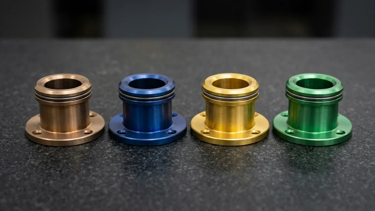
As shown below on four CNC-turned Ti-6Al-4V stepped flanged bearing bushings resting flat on their four-hole circular flanges, stepping DC voltage across 15 V, 30 V, 55 V, and 94 V transitions the TiO2 film through bronze, royal blue, golden yellow, and emerald green while preserving central bores and external O-ring grooves.
| CP Grade 2 Voltage (V DC) | Ti-6Al-4V (Grade 5 / 23) Voltage | TiO₂ Oxide Thickness (nm / µin) | Interference Hue & Order | Recommended Application / When to Choose |
|---|---|---|---|---|
| 12 V – 16 V | 15 V – 20 V | 20 – 30 nm (0.79 – 1.18 µin) | Warm Bronze / Straw Gold (1st Order) | Choose for Ø3.5 mm orthopedic cortical bone screws, dental healing abutments, and low-voltage fluid couplings. |
| 20 V – 25 V | 24 V – 29 V | 35 – 44 nm (1.38 – 1.73 µin) | Deep Violet / Royal Purple (1st Order) | Choose for high-contrast left-hand thread aerospace nuts and spinal pedicle screw diameter coding. |
| 26 V – 32 V | 30 V – 36 V | 45 – 56 nm (1.77 – 2.20 µin) | Dark Cobalt / Royal Blue (1st Order) | Choose as the primary surgical tray size identifier and standard aerospace AN/MS fluid fitting color code. |
| 35 V – 42 V | 38 V – 46 V | 60 – 74 nm (2.36 – 2.91 µin) | Sky Blue / Ice Cyan (1st–2nd Transition) | Choose for secondary surgical instrument handles and optical sensor mount rings requiring bright visual contrast. |
| 50 V – 58 V | 54 V – 62 V | 82 – 98 nm (3.23 – 3.86 µin) | Bright Golden Yellow (2nd Order) | Choose for dental implant prosthetic platforms (warm gingival tone through thin tissue) and trauma locking plates. |
| 68 V – 78 V | 72 V – 84 V | 110 – 130 nm (4.33 – 5.12 µin) | Rose Pink / Vibrant Magenta (2nd Order) | Choose for dental transmucosal abutments and high-visibility orthopedic trauma fixation screws. |
| 88 V – 98 V | 92 V – 105 V | 138 – 150 nm (5.43 – 5.91 µin) | Vivid Emerald / Teal Green (2nd Order) | Choose for large-diameter orthopedic intramedullary nails and thickest barrier corrosion protection in Type III baths. |
3. AMS 2488 Type II Anti-Galling vs Type III Biocompatible Color Anodizing
When specifying titanium surface treatments on engineering drawings, hardware teams must distinguish between tribological anti-galling conversion coatings (AMS 2488 Type II) and thin-film interference color coding (AMS 2488 Type III and ASTM F86). Confusing these two specifications can lead to seized aerospace actuators or unintended fatigue debit on dynamic airframe links.
Bare titanium alloys suffer from notorious adhesive wear and cold welding (galling) when sliding against mating titanium or stainless steel surfaces under contact stress. Because titanium’s natural passive film is only 2 nm to 5 nm (0.08 to 0.20 µin) thick, local asperity shearing strips the oxide and welds nascent metal junctions together.
To prevent galling, AMS 2488 Type II titanium anodizing immerses the workpiece in a concentrated alkaline electrolyte (pH ≥ 12.5–13, typically sodium hydroxide or potassium hydroxide with complexing agents) under high DC voltage. This electrochemical reaction converts the outer surface into a dense, matte dark-charcoal gray ceramic layer measuring 1.0 µm to 2.5 µm (0.04 to 0.10 thou).
In aerospace flight hardware manufacturing, AMS 2488 Type II serves two critical structural functions. First, its micro-textured gray oxide retains solid dry-film lubricants (such as MoS2 or PTFE) to eliminate thread seizure on actuator shafts, clevis pins, and hydraulic fittings. Second, it provides dielectric insulation between titanium brackets and carbon-fiber-reinforced polymer (CFRP) skins, preventing galvanic corrosion.
In contrast, AMS 2488 Type III (and ASTM F86 in surgical implant applications) targets visual size coding, part traceability, and glare reduction in precision medical device components. Because Type III films measure only 15 nm to 150 nm (0.015 to 0.15 µm / 0.59 to 5.91 µin), diameter change stays below 0.0004 mm (0.016 thou).
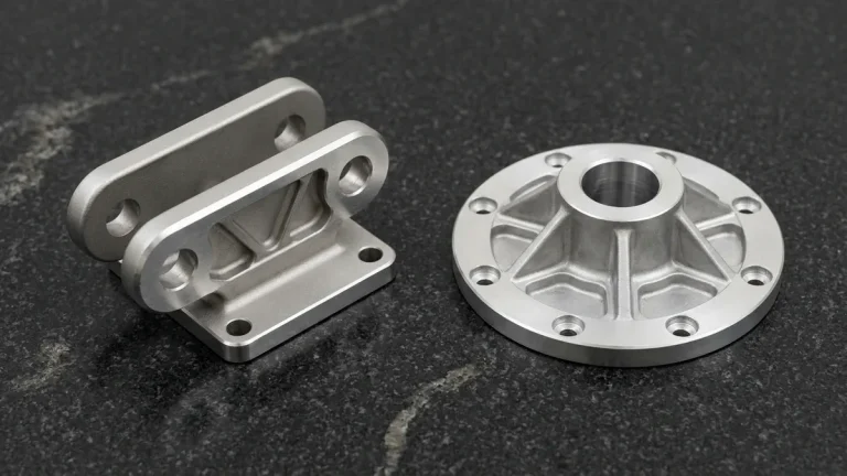
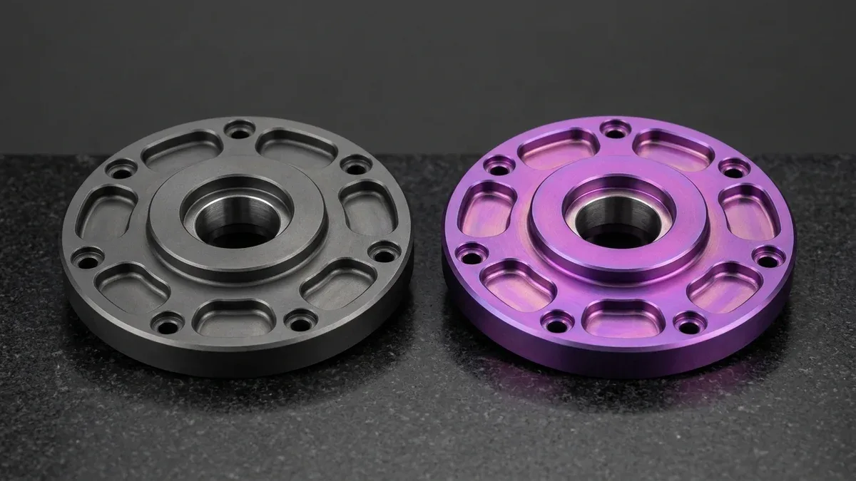
As shown below on two CNC-machined Ti-6Al-4V concentric stepped rotary adapter flanges featuring counterbored perimeter bolt circles, radial scalloped weight-reduction pockets, and central precision bearing bores, the left flange displays the dense matte charcoal-gray AMS 2488 Type II conversion finish while the right flange displays a vibrant magenta-purple Type III interference finish.
| Process Classification | Electrolyte Chemistry & Voltage | Oxide Thickness (Metric / Imperial) | Dimensional Allowance Required? | Recommended Application / When to Choose |
|---|---|---|---|---|
| Type I (Adhesive Bonding Prep) | Chromic / phosphoric or alkaline bath (10 V – 20 V DC) | 10 – 25 nm (0.39 – 0.98 µin) | No (Zero measurable growth) | Choose for structural adhesive bonding preparation of titanium honeycomb panels and thermal-forming oxidation masks. |
| AMS 2488 Type II (Heavy Anti-Galling) | Concentrated alkaline solution, pH > 13 (15 V – 80 V DC) | 1.0 – 2.5 µm (0.04 – 0.10 thou) | Minor (~0.5 – 1.0 µm per side on ultra-tight fits) | Choose for sliding aerospace mechanisms, hydraulic valve spools, clevis joints, and CFRP galvanic isolation brackets. |
| AMS 2488 Type III / ASTM F86 (Color Spectrum) | Dilute phosphoric/sulfuric acid electrolyte (10 V – 105 V DC) | 15 – 150 nm (0.59 – 5.91 µin) | No (< 0.0004 mm diameter change; preserves ±0.005 mm / ±0.0002 in fits) | Choose for orthopedic bone screws, trauma plates, dental abutments, and flight-line fastener identification. |
| Plasma Electrolytic Oxidation (PEO / MAO) | High-voltage pulsed silicate/phosphate bath (250 V – 500 V AC/DC) | 10.0 – 45.0 µm (0.39 – 1.77 thou) | Yes (Mask ±0.010 mm bores and fine threads) | Choose when titanium parts face severe abrasive slurry wear, high dielectric breakdown (>1,000 V), or marine erosion. |
4. Pre-Treatment Chemistry: Alkaline Degreasing & HNO₃/HF Acid Pickling SOP
In aerospace and medical surface finishing lines, 85% of color non-uniformity and dielectric pitting defects originate during pre-anodizing chemical preparation rather than in the anodizing tank itself. Raw CNC-machined titanium carries a passive oxide film of uneven thickness alongside trace iron or tungsten carbide transfer from cutting tools.
Furthermore, if elevated cutting temperatures during dry or low-coolant roughing create a localized oxygen-enriched surface layer (alpha-case), that brittle zone exhibits drastically different electrical resistivity than the underlying metal. Unless completely stripped by chemical etching, alpha-case patches appear as dull matte islands after electrochemical processing.
If free iron particles remain embedded in a titanium surface during anodizing, electrical current concentrates at those low-resistance iron inclusions, causing localized oxygen gas evolution, micro-arcing burns, and dull gray halo spots. Standard nitric acid passivation (ASTM F86 / ASTM A967, 20%–45% vol HNO3) dissolves free iron, but nitric acid alone cannot etch titanium oxide.
To strip native mill oxides and expose a chemically homogeneous surface, our finishing line executes a controlled nitric-hydrofluoric acid (HNO3 + HF) pickling sequence. Hydrofluoric acid dissolves TiO2 and 1 µm to 3 µm (0.04 to 0.12 thou) of base metal via 3Ti + 4HNO3 + 12HF → 3H2TiF6 + 4NO + 8H2O.
- Execute Ultrasonic Alkaline Degreasing & Cascade DI Rinsing: Immerse CNC-machined titanium parts in an inhibited non-silicated alkaline surfactant bath at 55°C to 65°C (131°F to 149°F) with 40 kHz ultrasonic agitation for 5 to 10 minutes to saponify water-soluble coolants and cutting oils, followed by a double counter-flow deionized (DI) water rinse (resistivity ≥ 1.0 MΩ·cm).
- Perform Controlled 10:1 Nitric-Hydrofluoric (HNO3 + HF) Acid Pickling (ASTM B600): Transfer racked components into an acid activation bath containing 15% to 25% by volume nitric acid (HNO3) and 1.5% to 2.5% by volume hydrofluoric acid (HF) (or 30%–40% HNO3 with 2%–4% HF for heavy mill scale) in DI water at 20°C to 30°C (68°F to 86°F) for 30 to 90 seconds. Maintain the HNO3 : HF volumetric ratio strictly at ≥10 : 1; excess oxidizing nitric acid converts nascent atomic hydrogen into water, keeping hydrogen absorption safely below the 125 ppm to 150 ppm embrittlement limit on thin-walled Ti-6Al-4V sections.
- Clamp Workpieces on Spring-Loaded Titanium Racks & Regulate DC Voltage Ramp: Secure parts using high-pressure CP Grade 2 or Ti-6Al-4V spring clips at designated non-cosmetic contact points (never use aluminum racks, which rapidly dissolve in the electrolyte and steal electrical current from the titanium load). Immerse in the electrolyte bath and ramp DC voltage at 2 V/s to 5 V/s to the target setpoint within ±0.3 V accuracy until current density decays to its self-limiting plateau (typically 15 to 45 seconds).
- Complete Deionized Water Cascade Rinsing, Hot-Air Drying & Colorimetric Verification: Immediately rinse parts in flowing DI water, followed by an ultrasonic DI water bath and filtered 65°C (149°F) hot-air drying to prevent mineral water-spot staining, then verify L*a*b* color coordinates and dimensional tolerances.
5. CNC Machining Surface Finish Pre-Conditioning & Tolerance DFM Rules
Because a Type III anodic TiO2 film is only 15 nm to 150 nm (0.59 to 5.91 µin) thick—roughly 100 times thinner than a single human red blood cell—it conforms 1:1 to the underlying machined substrate topography. Titanium anodizing never hides machining cutter marks, burrs, or chatter; instead, the high-index oxide layer magnifies surface texture variations.
In our Shenzhen machine shop, high-speed 3-axis and 4-axis vertical machining centers (VMCs) with rigid precision vises or custom contoured soft jaws serve as the primary workhorse for 80%+ of titanium plates, clevis brackets, and sensor housings, holding general tolerances to ISO 2768-mK and critical mating bores to ±0.010 mm to ±0.020 mm (±0.0004 in to ±0.0008 in).
Simultaneous 5-axis CNC milling is deployed selectively for compound-angle orthopedic implants and contoured aerospace manifolds, while Swiss-type CNC turning centers machine slender bone screws and actuator pins. When bearing journals or valve spools demand ±0.005 mm (±0.0002 in) diameter tolerances and ≤ 0.005 mm (0.0002 in) concentricity, our machinists finish-grind or hone the titanium before anodizing.
To prevent a mottled work-hardening layer or alpha-case heat tint that shifts anodic color, our machinists finish Ti-6Al-4V using climb milling with sharp variable-helix carbide end mills at Vc = 45–65 m/min (148–213 SFM) and fz = 0.04–0.08 mm/tooth (0.0016–0.0031 in/tooth) under high-pressure coolant to suppress tool deflection and notch wear.
To achieve repeatable color appearance and reflection behavior across custom surface finishes, mechanical engineers must explicitly specify the pre-anodizing substrate surface roughness (Ra per ISO 4287 / ASME B46.1) on the 2D manufacturing drawing according to three functional finishing tiers:
- Precision Turned / Fine Milled Finish (Ra 0.2 µm to 0.4 µm / 8 µin to 16 µin): Specular reflection dominates, yielding vivid, jewel-like metallic interference colors with maximum chromatic saturation, ideal for color-coded dental abutments and external aerospace fittings.
- Standard CNC Milled Finish (Ra 0.8 µm to 1.6 µm / 32 µin to 63 µin): Produces a clean directional satin sheen where toolpath stepovers remain visible beneath the colored oxide film, suitable for internal structural brackets and manifold blocks.
- Fine Glass-Bead Blasted Matte Finish (#120 to #180 Mesh Glass Media, Ra 1.2 µm to 2.4 µm / 47 µin to 95 µin): Creates an isotropic, low-glare diffuse surface that eliminates harsh surgical lamp reflections in the operating room; note that diffuse scattering softens color saturation and requires +2 V to +4 V adjustment to match polished color standards.
Additionally, every anodized titanium part requires positive electrical contact via a spring-loaded titanium rack finger (never aluminum racking, which dissolves and steals current). Because TiO2 is an electrical insulator, the 0.5 mm to 1.2 mm (0.020 in to 0.047 in) contact point remains bare; designers should specify an internal counterbore or non-critical face for racking.
When designing multi-color titanium assemblies—such as surgical instrument handles requiring a matte gray body with a gold or blue torque-limit collar band—higher-voltage colors must always be anodized first. Our technicians then precision-mask the high-voltage zone, chemically strip the secondary region in HNO3/HF, and re-anodize at the lower voltage setpoint.
6. When NOT to Choose Titanium Anodizing: Process Limitations & Trade-Offs
Although titanium anodizing excels at anti-galling conversion (AMS 2488 Type II) and zero-build-up color identification (Type III), hardware engineers must recognize three fundamental physical boundaries during DFM review where alternative PVD ceramic coatings or pre-anodizing mechanical surface treatments are required:
- Inability to Produce True Red or Pure Jet Black in Type III Baths: Because Type III color arises from constructive and destructive wave interference in a transparent TiO2 layer rather than light-absorbing pigments, second-order interference around 65 V to 80 V mixes red and blue wavelengths into magenta, rose, or violet—never a pure 650 nm ruby red. Similarly, transparent interference cannot absorb 100% of visible light to create jet black; when applications require a true black titanium finish, specify Diamond-Like Carbon (DLC) or PVD TiAlN/CrN coating, or use dark charcoal-gray AMS 2488 Type II.
- Zero Heavy Abrasive Wear Protection from Nanometer Type III Films: A 15 nm to 150 nm (0.59 to 5.91 µin) Type III interference layer is easily scratched by hard metallic contact or abrasive particles under contact pressures exceeding 300 MPa (43.5 ksi). Do not specify Type III color anodizing for high-load sliding bearings or wear plates; choose AMS 2488 Type II (1.0 µm to 2.5 µm) with bonded solid film lubricant or PVD titanium nitride (TiN, 2,200 HV).
- High-Cycle Fatigue (HCF) Debit on Thick Type II Layers: Growing a dense 1.0 µm to 2.5 µm (0.04 to 0.10 thou) ceramic conversion layer in an alkaline Type II bath can introduce micro-fissures that reduce the high-cycle fatigue endurance limit of dynamic Ti-6Al-4V aerospace links by 10% to 18%. For fatigue-critical flight brackets, specify controlled glass-bead or shot peening prior to Type II anodizing to lock in compressive residual surface stress, or mask high-stress fillet radii.
| Observed Surface Defect | Root Physical / Electrochemical Cause | Shop-Floor Corrective Action | Recommended Application / When to Choose |
|---|---|---|---|
| Blotchy Rainbow Halos / Color Shift Across Part | Residual cutting oil film, uneven native oxide, or loose titanium rack contact causing local IR voltage drop (ΔV > 2 V). | Run 40 kHz ultrasonic alkaline degreasing, refresh 20% HNO3 + 2% HF (10:1) pickle for 45 s, and increase titanium spring-clip clamping force. | Choose strict ±0.3 V DC rectifier regulation and dedicated spring-loaded Ti-6Al-4V racks for multi-cavity surgical screw batches. |
| Localized Gray Pitting / Dielectric Burn Spots | Smeared iron/steel contamination from worn tooling or chloride ion (>50 ppm) contamination in the electrolyte bath. | Machine titanium exclusively with sharp dedicated carbide tooling, pickle in 10:1 HNO3/HF to dissolve embedded iron, and use ≥1.0 MΩ·cm DI water. | Choose dedicated iron-free finishing lines when anodizing thin-walled aerospace hydraulic sleeves at voltages above 60 V DC. |
| Washed-Out, Milky, or Chalky Interference Color | Excessive HNO3/HF pickling time (>120 s) or depleted HF concentration causing selective alpha-beta grain boundary etching. | Restrict acid immersion to 30–60 s at 22°C (72°F), maintain a 10:1 HNO3:HF ratio (20% HNO3 / 2% HF), and specify pre-anodize Ra ≤ 0.4 µm (16 µin). | Choose fine CNC turning or electropolishing before Type III anodizing when high-saturation specular colors are required. |
| Unanodized Voids Inside Blind Tapped Holes | Oxygen gas bubbles trapped inside horizontal or downward-facing blind bores (L/D > 2.5) blocking electrolyte contact. | Orient blind bores upward at a 30°–45° tilt angle on the titanium rack and apply mechanical electrolyte agitation or air sparging. | Choose through-drilled tapped holes or add 1.5 mm (0.060 in) gas-relief vent passages on complex manifolds whenever DFM permits. |
| Powdery Smut on AMS 2488 Type II Gray Coating | Excessive bath temperature (>35°C / 95°F) or prolonged dwell time in high-alkaline Type II electrolyte causing outer oxide friability. | Chill alkaline tank to 20°C–25°C (68°F–77°F) with heat exchangers and perform a controlled wet glass-bead post-clean per AMS 2488. | Choose chill-regulated Type II alkaline baths for high-load aerospace clevis pins and splined actuator shafts. |
7. Quality Metrology, Inspection Protocols & Ex-Factory Lead Times
Because Type III interference films are measured in nanometers and Type II coatings govern aerospace galling resistance, our 20°C ± 1°C (68°F ± 1.8°F) metrology laboratory enforces multi-stage verification before shipment. Every incoming titanium lot undergoes X-ray fluorescence (XRF) positive material identification (PMI) to confirm Ti-6Al-4V (Grade 5), Grade 23 ELI, or CP Grade 2 chemistry.
Before racking, our quality inspectors verify substrate surface roughness (Ra and Rz per ISO 4287 / ASME B46.1) using diamond-stylus profilometers. Tight-tolerance internal bearing bores (±0.010 mm / ±0.0004 in) and external shaft journals are inspected using 3-point internal bore micrometers, calibrated pin gauges, and calibrated digital external micrometers.
For complex 3-axis, 4-axis, and 5-axis milled titanium housings and rotary flanges, our metrology team performs dimensional verification on our 2.5D Optical Vision Measuring System (VMS) and, upon engineering request, full 3D coordinate verification on our Zeiss Contura Bridge CMM accompanied by a Ballooned Drawing & Full-Dimensional FAI Report (Form 1/2/3 Accountability Layout).
Post-anodizing inspection includes calibrated GO/NO-GO thread plug and ring gauge testing (confirming zero pitch-diameter interference on 6g/6H threads), ASTM D3359 cross-hatch tape adhesion verification, eddy-current / XRF coating thickness verification on Type II conversion layers, and visual/colorimetric comparison under standardized D65 (6500K) daylight illumination against master voltage witness coupons.
To support agile hardware development schedules without misleading transit promises, our production control team states all manufacturing lead times as Ex-Factory Production & Inspection Turnaround, strictly decoupled from international express air freight transit across three standard titanium machining and finishing execution tiers:
- Rapid CNC Titanium Prototypes (As-Machined / Passivated): 4–8 business days ex-factory production and metrology turnaround.
- CNC Titanium Prototypes with AMS 2488 Type II or Type III Anodizing: 7–12 business days ex-factory turnaround (including ultrasonic degreasing, 10:1 HNO3/HF pickling, custom titanium racking, anodizing, and final QC).
- Low-to-Mid Volume Production Runs (10 to 1,000+ Titanium Parts): 7–30 business days ex-factory turnaround depending on multi-axis complexity and batch lot size, plus 3–5 business days international express air transit (DHL / FedEx / UPS).
🔗 Related Titanium & Surface Engineering Guides
8. Technical Engineering FAQ
No, Type III titanium anodizing uses zero organic dyes, generating spectrum hues through thin-film optical interference across a transparent 15 nm to 150 nm (0.59 to 5.91 µin) titanium dioxide layer. This nanoscale barrier adds negligible thickness, preserving 6g/6H threads and ±0.005 mm (±0.0002 in) bearing journals.
AMS 2488 Type II uses a high-voltage alkaline electrolyte (pH > 13) to grow a 1.0 µm to 2.5 µm (0.04 to 0.10 thou) anti-galling dark-gray oxide. Conversely, Type III grows a 15 nm to 150 nm (0.59 to 5.91 µin) interference film for biocompatible color coding.
Because anodic titanium dioxide is optically transparent, wave interference mixes multiple visible wavelengths simultaneously rather than isolating pure 650 nm red or absorbing all light for black. When hardware requires a dark finish, engineers specify matte charcoal AMS 2488 Type II anodizing or black DLC PVD coatings.
Immersion in a 10:1 volumetric bath of 15% to 25% nitric acid and 1.5% to 2.5% hydrofluoric acid strips uneven mill oxides and smeared iron transfer. This oxidizer-rich ratio suppresses atomic hydrogen absorption safely below the 125 to 150 ppm embrittlement threshold.
Ready to Optimize Your Custom Parts for Precision Manufacturing?
Upload your 3D CAD models (STEP/IGES) and 2D technical drawings for a comprehensive DFM review covering Ti-6Al-4V CNC machining tolerances, racking contact placement, and AMS 2488 Type II or Type III titanium anodizing specifications. Our in-house engineering team validates every surface roughness callout and thread fit to ensure flawless functional performance.
Request a Technical DFM & Custom Quote →