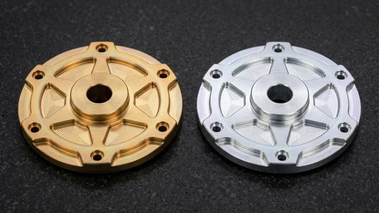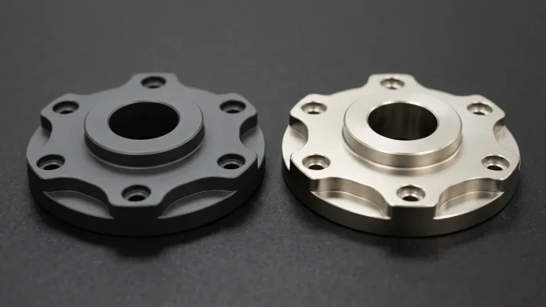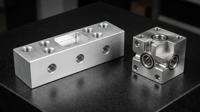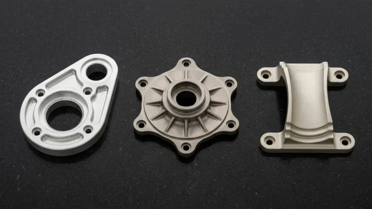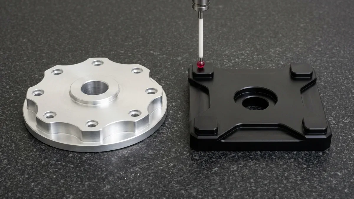
In high-consequence hardware engineering, dimensional accuracy is never a statistical accident—it is the physical result of disciplined quality control in manufacturing executed across every production stage. When machining hydraulic valve manifolds, robotic actuator housings, or surgical instruments, a bore deviation of just ±0.010 mm (±0.0004″) can trigger bearing seizure, seal blow-by, or premature fatigue failure.
Rather than treating inspection as a passive sorting filter at the shipping dock, our Shenzhen CNC facility integrates a four-gate closed-loop metrological architecture. By combining X-ray fluorescence (XRF) alloy verification, automated spindle touch probing, real-time Statistical Process Control (SPC), and climate-stabilized Coordinate Measuring Machine (CMM) verification, our in-house engineering team eliminates dimensional drift before scrap occurs.
This engineering guide details the physical mechanics, mathematical capability models, and shop-floor inspection standards that govern modern precision manufacturing. Hardware leads and technical buyers will find actionable benchmarks for Incoming Quality Control (IQC), In-Process Quality Control (IPQC), statistical capability indices (Cp and Cpk), and Outgoing Quality Control (OQC) documentation.
Executive Summary & Engineering Takeaways (BLUF)
- Four-Gate Inspection Sequence: Production parts pass through four mandatory physical checkpoints—IQC raw stock alloy/hardness screening, First-Piece IPQC buy-off, hourly Patrol SPC subgroup sampling, and Final OQC in a 20.0°C ± 1.0°C (68.0°F ± 1.8°F) metrology lab.
- Realistic Shop-Floor Tolerance Tiers: General unnoted CNC features follow ISO 2768-mK (±0.10 mm to ±0.30 mm / ±0.0039″ to ±0.0118″ for 0.5–120 mm features), critical mating bores and dowel fits hold ±0.010 mm to ±0.020 mm (±0.0004″ to ±0.0008″), and Wire EDM or precision grinding reaches ±0.005 mm (±0.0002″).
- Statistical Capability Thresholds: Batch machining setups target a centered process capability index of Cpk ≥ 1.33 (≤ 63 defective parts per million) for standard tight tolerances and Cpk ≥ 1.67 for critical bearing journals and sealing lands.
- Process-Matched Metrology Instruments: Rigid metal CNC datums and 3D GD&T callouts per ASME Y14.5 are verified via bridge CMM ruby probing and 3-point internal bore micrometers, whereas flexible sheet metal and polymer parts use non-contact 2.5D optical vision systems (VMS) and mating fit-up fixtures.
- Turnaround & Traceability Deliverables: Ex-factory production and inspection turnaround spans 4–8 business days for rapid prototypes, 7–12 business days with surface finishing, and 7–30 business days for production runs (plus 3–5 business days express air transit), accompanied by EN 10204 3.1 MTRs, CMM reports, and Ballooned Drawing & Full-Dimensional FAI Reports [Form 1/2/3 Layout].
Article Engineering Navigation
- 1. QA vs. QC: Closed-Loop Manufacturing Architecture
- 2. Gate 1 — Incoming Quality Control (IQC)
- 3. Gate 2 — In-Process Quality Control (IPQC) & Probing
- 4. Gate 3 — Statistical Process Control (Cp & Cpk)
- 5. Gate 4 — Outgoing Quality Control (OQC) & 20°C Lab
- 6. Defect Troubleshooting & Metrology DFM Matrix
- 7. When NOT to Over-Specify Inspection & Trade-Offs
- 8. Technical Engineering FAQ
1. Quality Assurance (QA) vs. Quality Control (QC): Closed-Loop Manufacturing Architecture
In industrial production, engineers frequently conflate Quality Assurance (QA) and Quality Control (QC), yet the two disciplines operate on opposite sides of the cutting tool. Quality Assurance is a proactive, systems-level engineering framework designed to stabilize manufacturing workflows, prevent process variation, and eliminate failure modes before spindle rotation begins.
Our engineering team executes QA during the pre-production phase through comprehensive Design for Manufacturing (DFM) engineering review, Process Failure Mode and Effects Analysis (PFMEA), workholding rigidity simulation, and gauge Repeatability and Reproducibility (Gauge R&R) validation. By locking down cutting speeds, feed rates, and fixture datum locations upfront, QA ensures the machining cell is inherently repeatable.
Conversely, Quality Control (QC) is the physical, measurement-driven execution of verifying raw materials, in-process workpieces, and finished components against 2D engineering blueprints and 3D CAD geometry. QC technicians use calibrated micrometers, pin gauges, surface profilometers, and bridge CMMs to measure physical hardware and generate quantitative pass/fail acceptance records.
- Proactive Prevention (QA Scope): Encompasses CAD tolerance stack-up analysis, CAM toolpath collision verification, fixture clamping stress control, preventive spindle maintenance, and NIST-traceable master gauge calibration schedules.
- Tactical Verification (QC Scope): Encompasses handheld XRF alloy chemistry verification, on-machine spindle touch probing, hourly SPC dimensional subgroup charting, ASME Y14.5 GD&T coordinate metrology, and pneumatic pressure decay leak testing.
- Closed-Loop Feedback Integration: In our Shenzhen machine shop, QC inspection data never sits idle in a filing cabinet; real-time dimensional trends flow directly back to CAM programmers and CNC operators to compensate for tool wear and thermal drift.
2. Gate 1 — Incoming Quality Control (IQC): Alloy PMI, MTR Heat-Lot Audits & Hardness Testing
Zero-defect precision CNC machining services begin at the receiving bay long before raw billet or bar stock reaches a machine vise. If an upstream mill supplies extruded 6063 architectural aluminum disguised as 6061-T651 plate, or annealed 4140 steel instead of pre-hardened stock, parts will warp during pocketing or fail under mechanical load.
At Gate 1, our Incoming Quality Control (IQC) inspectors quarantine every incoming batch of metallic and polymeric raw stock until three physical verification checks match the accompanying EN 10204 3.1 Mill Test Report (MTR) heat lot numbers. Every raw billet receives a traceable barcoded traveler tag that follows the job through machining, finishing, and final packaging.
First, inspectors perform Positive Material Identification (PMI) using a handheld X-ray fluorescence (XRF) alloy analyzer. Within a 5–15 second multi-beam test, the XRF spectrometer measures elemental mass percentages—such as 5.1%–6.1% zinc and 2.1%–2.9% magnesium in 7075-T651 aluminum, or 16%–18% chromium and 2.0%–3.0% molybdenum in 316L stainless steel—preventing alloy mix-ups.
- MTR Heat-Lot & Mill NDT Traceability Audit: Incoming aerospace and hydraulic manifold billets (thickness ≥ 40 mm / 1.57″) are cross-checked against upstream mill chemical and ultrasonic inspection logs to confirm freedom from subsurface centerline porosity, inclusions, or lamination cracks before spindle time is invested.
- Temper & Hardness Verification (ASTM E18 / E384): Heat-treated alloys such as 17-4PH stainless steel (Condition H900 at 40–44 HRC), 4140 alloy steel (28–32 HRC), and 7075-T651 aluminum (87 HRB / ~150 HB) are tested on calibrated Rockwell (HRC/HRB) and Vickers HV hardness testers to confirm proper precipitation or quench-and-temper states.
- Raw Stock Dimensional & Stress Relief Audit: Ground bar stock for Swiss-type lathes is checked with digital external micrometers (1 µm / 0.00004″ resolution) and granite surface plates for diameter consistency and straightness, while engineering plastics (PEEK, POM, PEI) are verified for pre-machining annealing records.
3. Gate 2 — In-Process Quality Control (IPQC): First-Piece Buy-Off & On-Machine Touch Probing
In modern precision machine shops, high-speed 3-axis and 4-axis vertical machining centers (VMCs) handle 75% to 85% of prismatic brackets, enclosures, cold plates, and fluid manifolds, while simultaneous 5-axis centers are reserved for complex impellers and compound-angle aerospace contours. Across both platforms, catching dimensional drift inside the vise is 10x more cost-effective than scrapping finished lots.
Before releasing batch production, the first machined part from each setup undergoes mandatory First Article Inspection (FAI) buy-off logged in a Ballooned Drawing & Full-Dimensional FAI Report [Form 1/2/3 Layout]. Independent IPQC inspectors verify every ballooned callout—from ISO 2768-mK walls to ISO 286 H7 (+/0) and JS6 bearing seats held within ±0.008–±0.012 mm (±0.0003″–±0.0005″).
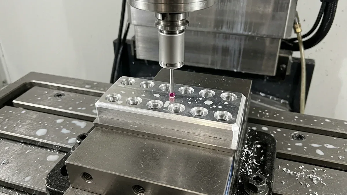
To eliminate manual edge-finding errors in high-speed 3-axis and 4-axis CNC milling, our VMCs deploy spindle-mounted optical ruby touch probes. Below, on a milled 6061-T6 aluminum two-row fluid manifold block clamped in wide steel vise jaws, the vertical ruby stylus contacts the top datum plane between spotfaced ports to verify Z-height and port true position.
Our shop floor executes a standardized four-step IPQC and on-machine probing Standard Operating Procedure (SOP) on every multi-setup CNC job:
- Calibrate Spindle Ruby Stylus Against Master Ring Gauge: Prior to setup, the CNC operator cycles the spindle touch probe against a ground master setting ring gauge and reference block to dial in stylus radial runout ≤ 0.005 mm (5.0 µm / 0.0002″) TIR and calibrate 3D trigger repeatability within ±0.005 mm (±0.0002″).
- Establish Work Coordinate System (WCS) & Angular Skew Compensation: The ruby stylus probes two points along the fixed Kurt vise jaw or billet reference edge to calculate angular misalignment, automatically updating G54–G59 coordinate offsets and rotating the toolpath frame.
- Execute First-Piece Off-Machine Metrology Buy-Off: After Op-10 cutting finishes, the first workpiece is cleaned and routed to the IPQC station for full dimensional verification using 3-point internal bore micrometers, depth micrometers, and GO/NO-GO thread plug gauges before unlocking batch production.
- Automate Closed-Loop Tool Wear & Patrol Inspection Updates: During production, the spindle probe checks critical pocket widths and datum steps every 5 to 10 parts to auto-adjust dynamic cutter radius wear registers, supplemented by roving IPQC patrol checks every 1 to 2 hours.
4. Gate 3 — Statistical Process Control (SPC): Process Capability (Cp/Cpk) & Drift Prevention
When manufacturing low-to-mid volume batches of 50 to 5,000+ components on CNC turning and Swiss-type lathe centers, pass/fail GO/NO-GO gauging alone cannot warn machinists that carbide insert flank wear or ballscrew heating is pushing dimensions toward the tolerance boundary. Statistical Process Control (SPC) quantifies process dispersion in real time.
During active production, patrol inspectors measure subgroups of n = 5 consecutive workpieces at scheduled intervals and plot the subgroup mean (X-bar) and range (R) on digital control charts (using n = 5 constants A2 = 0.577, D3 = 0, D4 = 2.114). Process capability is evaluated via Cp and Cpk:
Where USL and LSL are Upper and Lower Specification Limits, μ is the process mean, σ is within-subgroup standard deviation (σ = R-bar ÷ d2, with d2 = 2.326 for n = 5), α is the thermal expansion coefficient (µm/m·°C), L0 is nominal length, and ΔX, ΔY are coordinate offsets from basic dimensions.
Worked Shop-Floor Calculation: For a CNC-turned ⌀12.000 ± 0.012 mm (0.4724″ ± 0.0005″) 17-4PH bearing journal, USL = 12.012 mm, LSL = 11.988 mm, and tolerance width T = 0.024 mm (0.00094″). Across 25 five-piece subgroups (R-bar = 0.00465 mm), measured mean μ = 12.003 mm (0.47256″) and σ = 0.00465 ÷ 2.326 = 0.0020 mm (0.00008″):
- Potential Capability (Cp): Cp = (12.012 − 11.988) ÷ (6 × 0.0020) = 0.024 ÷ 0.0120 = 2.00 (confirming high machine tool stiffness and low random scatter).
- Upper Capability (Cpu): Cpu = (12.012 − 12.003) ÷ (3 × 0.0020) = 0.009 ÷ 0.0060 = 1.50.
- Lower Capability (Cpl): Cpl = (12.003 − 11.988) ÷ (3 × 0.0020) = 0.015 ÷ 0.0060 = 2.50.
- Resulting Centered Capability (Cpk): Cpk = min(1.50, 2.50) = 1.50 ≥ 1.33. Because Cpk exceeds our 1.33 threshold, the turning process is statistically capable; applying a −0.003 mm (−0.00012″) X-axis tool wear offset centers μ at 12.000 mm and raises Cpk to 2.00.
5. Gate 4 — Outgoing Quality Control (OQC): 20°C Bridge CMM, Optical VMS & Pressure Decay Testing
After subtractive machining, deburring, and surface finishing—such as MIL-A-8625 Type II/III anodizing, ASTM A967 citric/nitric passivation, or electroless nickel plating (ENP)—components enter our temperature-stabilized metrology laboratory for Final and Outgoing Quality Control (OQC). Without environmental temperature control, thermal expansion invalidates micron-level measurements.
Aluminum 6061-T6 expands at α = 23.6 µm/m·°C (13.1 µin/in·°F). Measuring a 150 mm (5.91″) bearing carrier plate on a 28.0°C (82.4°F) shop floor instead of the ISO 1 reference temperature of 20.0°C (68.0°F) adds ΔL = 23.6 × 0.150 × 8.0 = +0.0283 mm (+0.0011″), exceeding a +0.015 mm (+0.0006″) tolerance limit.
To eliminate thermal error, our metrology room is held at 20.0°C ± 1.0°C (68.0°F ± 1.8°F) and 45%–55% relative humidity, where parts thermally soak on Grade 00 black granite surface plates for 4 hours prior to inspection. This thermal normalization ensures that thick-walled aluminum manifolds and stainless steel shafts reach equilibrium with our master gauges.
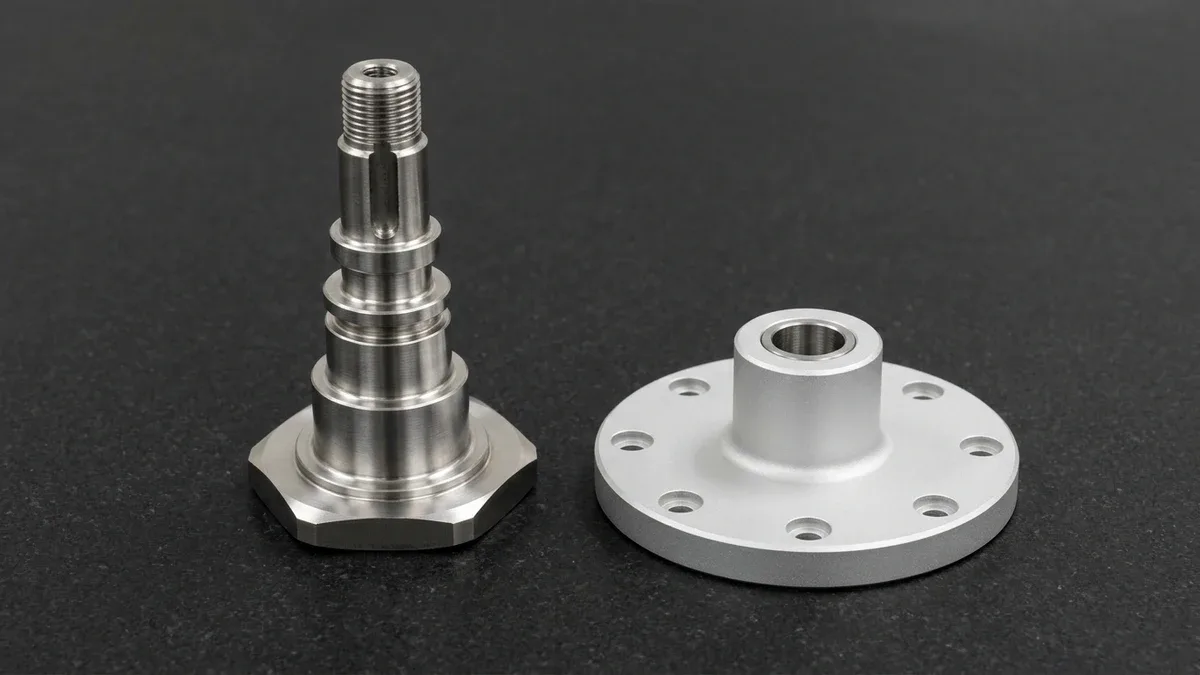
On our black granite inspection plate below, cylindrical workpieces like the 4-stepped 17-4PH stainless steel transmission shaft with milled wrench flats and circlip grooves rest horizontally across matched precision-ground steel V-blocks. Beside it, planar parts like the bead-blasted 6061-T6 aluminum pear-shaped twin-bore bearing carrier link plate sit completely flat on the granite datum plane.
Depending on part rigidity, feature geometry, and functional requirements, our OQC metrologists select from our in-house metrology and CNC equipment list to verify every specification:
- 3D Coordinate Metrology (Zeiss Contura Bridge CMM, Available Upon Request): Deployed for rigid CNC metal components to verify 3D GD&T tolerance zones per ASME Y14.5—including true position (⌀0.010 mm / ⌀0.0004″; e.g., coordinate offsets ΔX = +0.003 mm and ΔY = −0.004 mm yield TP = 2 × √(0.003² + (−0.004)²) = 0.010 mm / 0.0004″), coaxiality, perpendicularity, cylindricity, and surface profile (down to 0.005 mm / 0.0002″ zone width)—alongside linear coordinate tolerances down to ±0.005 mm (±0.0002″), Mitutoyo Holtest 3-point internal bore micrometers for H7/JS6 bearing seats, and ISO 14253-1 guard-band decision rules accounting for expanded measurement uncertainty (U95, k = 2).
- 2.5D Optical Vision Measurement System (VMS): Backlit telecentric optical stages perform rapid non-contact 2D coordinate measurement on micro-machined slots, thin stamped spring clips, and elastomeric or polymer parts that would deflect under tactile probe pressure.
- Surface Roughness, Coating Thickness & Salt Spray Verification: Diamond-stylus surface profilometers (ISO 4287 / ASME B46.1) measure Ra and Rz texture values on dynamic sealing lands (Ra 0.2–0.8 µm / 8–32 µin), while eddy-current/XRF gauges verify film build and ASTM B117 salt spray testing (24–240 hours) validates corrosion resistance.
- Differential-Pressure Air Decay Leak Testing: Liquid cooling plates, hydraulic valve bodies, and sealed housings undergo dry compressed air differential-pressure decay testing at 3.5 to 6.0 bar (0.35 to 0.60 MPa / 51 to 87 psi) or water-immersion bubble testing to confirm leak-tight integrity before shipment.
- ISO 2859-1 (ANSI/ASQ Z1.4) Zero-Acceptance (c = 0) Lot Sampling: While critical H7/h6 bearing fits and primary datums undergo 100% inspection, batch production runs are audited under ISO 2859-1 General Inspection Level II sampling (AQL 0.65 for critical features, AQL 1.0 for major dimensions, and AQL 2.5 for cosmetic surfaces) with strict c = 0 zero-acceptance criteria (any single non-conforming sample triggers 100% lot screening).
| QC Gate Stage | Primary Verification Scope | In-House Metrology Equipment | Acceptance Standard / Tolerance Band | Quality Deliverables | Recommended Application / When to Choose |
|---|---|---|---|---|---|
| Gate 1: IQC (Incoming) | Elemental alloy chemistry, temper hardness, MTR heat-lot audit, bar stock diameter | Handheld XRF analyzer (PMI), Rockwell HRC / Vickers HV hardness testers, digital external micrometers | ASTM / AMS alloy composition; ASTM E18 / E384 hardness (e.g., 40–44 HRC on 17-4PH H900) | Verified EN 10204 3.1 Mill Test Report (MTR), XRF PMI log, IQC lot traveler | Mandatory on 100% of incoming metal billets, bar stock, and engineering plastics prior to sawing |
| Gate 2: IPQC (First-Piece & Probing) | WCS datum alignment, Op-10/Op-20 setup accuracy, bore sizing, thread pitch diameter | Spindle optical touch probe (ruby stylus), 3-point bore micrometers, pin gauges, GO/NO-GO thread gauges | ISO 2768-mK general; ±0.010 to ±0.020 mm (±0.0004″ to ±0.0008″) on critical fits | Ballooned Drawing & Full-Dimensional FAI Report [Form 1/2/3 Layout] | First piece of every new CNC fixture setup, tool change, or multi-axis datum flip |
| Gate 3: Patrol SPC (In-Run) | Tool wear drift, thermal spindle growth, subgroup mean (X-bar) and dispersion (R) | Digital micrometers, dial bore gauges, digital height gauges, matched steel V-blocks | Cpk ≥ 1.33 standard tight features; Cpk ≥ 1.67 safety-critical journals | X-bar / R control charts, capability histogram, offset log | Low-to-mid volume production runs (25 to 5,000+ pcs) requiring statistical stability proof |
| Gate 4: OQC (20°C Final Lab) | 3D GD&T true position/profile, surface roughness (Ra/Rz), coating thickness, leak tightness | Zeiss Contura Bridge CMM (upon request), 2.5D Optical VMS, Mitutoyo Holtest 3-point bore micrometers, ISO 4287 stylus profilometer, 3.5–6.0 bar differential-pressure air decay leak tester | ASME Y14.5 GD&T; ISO 1 (20.0°C); ISO 14253-1 guard-banding; ISO 2859-1 / ANSI/ASQ Z1.4 Level II (AQL 0.65 / 1.0 / 2.5, c = 0); ISO 4287 Ra 0.2–3.2 µm | CMM dimensional report, surface finish log, pressure test record, lot conformance report | Final release of all prototypes and production batches prior to VCI / EVA foam packaging |
6. Non-Conformance Root-Cause Troubleshooting Matrix & Metrology DFM Guidelines
When a dimensional or cosmetic non-conformance is flagged during IPQC or OQC, simply sorting out bad parts does not solve the underlying physics. Our engineering team conducts structured Root Cause Corrective Action (RCCA) investigations across Machine, Method, Material, Tooling, and Measurement variables to lock in permanent preventive fixes.
For example, when manufacturing tight-tolerance precision medical device components or optical mounts with thin 1.5 mm (0.059″) walls, three-jaw chuck clamping force can elastically deform a round bore into a trilobed triangle during boring. While the part measures round inside the chuck, unclamping releases elastic strain and causes out-of-roundness exceeding 0.025 mm (0.0010″).
Post-machining surface finishes also shift part dimensions through distinct physical mechanisms. MIL-A-8625 Type III hardcoat anodizing grows a 25 to 50 µm (0.0010″ to 0.0020″) oxide layer with 50% inward substrate penetration and 50% outward build, shrinking internal bore diameters by 1.0 × total film thickness.
Conversely, ASTM B733 electroless nickel plating deposits 100% outward, shrinking bore diameters by 2.0 × coat thickness and shifting 60° thread pitch diameters by 4 × coat thickness (or up to 8 × on electroplated crests). Meanwhile, ASTM A967 stainless steel passivation forms a ~0.002 µm passive oxide film with zero macro dimensional change.
| Observed Defect / Non-Conformance | Physical Root Cause Mechanism | Detection Metrology Gate | Shop-Floor Corrective Action (RCCA) | Recommended Application / When to Choose |
|---|---|---|---|---|
| Trilobed Bore Out-of-Roundness (> 0.015 mm / 0.0006″) | Excessive radial clamping pressure from standard 3-jaw hard jaws elastically distorting thin walls (t ≤ 2.0 mm / 0.079″) | IPQC 3-point internal bore micrometer & OQC CMM cylindricity scan | Switch to full-contact 360° contoured aluminum pie jaws (soft jaws) and reduce hydraulic chuck drawbar pressure before finish boring | Thin-walled bearing sleeves, optical lens barrels, and harmonic drive flexsplines |
| Gradual Bore Undersizing Across Batch (Cpk < 1.0) | Progressive carbide finishing insert flank wear combined with Z/X ballscrew thermal growth over multi-hour runs | On-machine spindle touch probe & Patrol SPC X-bar trend chart | Enable automated spindle probe closed-loop wear offset compensation every 10 parts and set tool-life forced swap counters | Batch CNC turning and milling runs exceeding 50 pieces in abrasive stainless or titanium alloys |
| Post-Anodize Pin Gauge Reject / Seized Thread Fit | Uncompensated outward oxide growth (+4 to +8 µm per face for Type II; +15 to +25 µm per face for Type III hardcoat) | OQC GO/NO-GO pin gauges, thread plug gauges & eddy-current film gauge | Machine pre-plate bores oversize by 2 × outward film build or apply silicone masking plugs into ±0.010 mm dowel bores and tapped holes | All MIL-A-8625 Type II/III anodized aluminum housings, manifolds, and precision plates |
| Large Plate Bowing / Flatness Deviation (> 0.05 mm / 0.002″) | Asymmetric removal of rolled skin residual stresses during heavy single-side pocket roughing | Granite surface plate with tapered feeler gauges & CMM flatness grid | Source stretched T651 plate, execute Op-10/Op-20 symmetric flip roughing leaving 0.5 mm (0.020″) stock, stress-relieve (150–165°C for 6061-T6; ≤100–110°C or 12–24h unclamped rest for 7075-T651), then skim-finish flat | Large aluminum baseplates, vacuum chucks, and liquid cold plates with high material removal ratios |
| Tapered Deep-Hole Bore Bell-Mouthing | Cantilever boring bar radial deflection and chip re-cutting at length-to-diameter ratios L/D > 4:1 | Two-level dial bore gauge & CMM star-stylus top-to-bottom circularity check | Switch to heavy-metal tungsten carbide anti-vibration boring bars, through-spindle high-pressure coolant, or precision honing | Deep hydraulic spool bores, actuator cylinders, and long stepped transmission sleeves |
7. When NOT to Over-Specify Inspection Protocols: Process Limitations & Economic Trade-Offs
A common engineering pitfall is applying rigid CNC metal metrology rules indiscriminately across every manufacturing process, or specifying ±0.010 mm (±0.0004″) tolerances and 100% full-feature bridge CMM scanning on non-critical clearance geometry. Over-specifying inspection adds unnecessary fixture cost and extends lead times without improving functional performance.
1. Never Specify Contact Bridge CMM Probing on Sheet Metal Stampings or Bent Enclosures: Thin sheet metal components (0.5–3.0 mm / 0.020″–0.118″ SPCC, SUS304, or 5052-H32 aluminum) show cold-bending springback, so bend angles hold ±0.5° to ±1.0° (ISO 2768-m angular class, legs up to 50 mm), and flex under tactile ruby probe contact force.
Inspecting flexible bent sheet metal on a bridge CMM produces false rejects due to clamping distortion. Instead, authoritative sheet metal quality control relies on mating cover fit-up assembly checks, dedicated checking fixtures, 90° knife-edge squares, radius gauges, and GO/NO-GO cylindrical pin gauges.
2. Never Use Contact CMM Stylus Probing on Polymer 3D Prints (SLA / SLS / MJF / FDM): Additive polymers experience ±0.15 mm to ±0.30 mm (±0.006″ to ±0.012″) thermal shrinkage and possess low elastic moduli. Touching a thin SLA resin wall or SLS PA12 nylon snap-fit hook with a physical CMM probe deflects the feature.
Consequently, polymer additive parts should be verified via non-contact 2.5D optical VMS, calibrated pin gauges, and physical mating assembly trials. Bridge CMM ruby probing is strictly reserved for rigid CNC post-machined datum faces and precision-reamed bores on DMLS metal prints.
3. Balance Inspection Granularity Against Cost & Turnaround Reality: Programming a multi-angle CMM routine to measure 150 ballooned dimensions on every part in a 200-piece batch increases unit cost by 1.3x–1.8x. Reserve 100% CMM probing for critical H7/h6 datums and mating bores while applying ISO 2859-1 Level II AQL sampling on ISO 2768-mK features.
This targeted inspection strategy preserves our fast Ex-Factory Production & Inspection Turnaround—4–8 business days for rapid prototypes, 7–12 business days with surface finishing, and 7–30 business days for production batches—strictly separated from 3–5 business days international express air transit via DHL, FedEx, or UPS.
🔗 Related Quality Control & CNC Metrology Engineering Guides
8. Technical Engineering FAQ
Incoming Quality Control (IQC) verifies raw material alloy chemistry via handheld XRF analyzers and hardness testers before machining starts. In-Process Quality Control (IPQC) uses spindle touch probes and patrol gauging during cutting, while Outgoing Quality Control (OQC) executes final 20°C bridge CMM verification before shipment.
For batch CNC production of tight-tolerance features such as ±0.010 mm to ±0.020 mm (±0.0004″ to ±0.0008″) bearing bores, our engineering team maintains a centered process capability index of Cpk ≥ 1.33. Safety-critical hydraulic sealing lands and aerospace interfaces are controlled to Cpk ≥ 1.67.
Unless specific geometric callouts are defined on your 2D blueprint, unnoted machined metal and polymer features are inspected to ISO 2768-mK (medium linear and class K geometric tolerances). Precision mating features are held to ±0.010 mm (±0.0004″), while Wire EDM and grinding reach ±0.005 mm (±0.0002″).
Every shipment includes traceable Mill Test Reports (MTR), XRF alloy verification logs, and full dimensional inspection sheets upon request. For complex assemblies and batch runs, our metrology lab provides Zeiss bridge CMM GD&T reports, SPC capability charts, and Ballooned Drawing & Full-Dimensional FAI Reports [Form 1/2/3 Layout].
Ready to Optimize Your Custom Parts for Precision Manufacturing?
Upload your 3D CAD models and 2D GD&T drawings for a comprehensive manufacturability and metrology inspection review by our Shenzhen engineering team. We verify critical datum structures, tolerance stack-ups, and pre-plating offsets to guarantee full dimensional compliance from prototype to production.
Request a Technical DFM & Custom Quote →