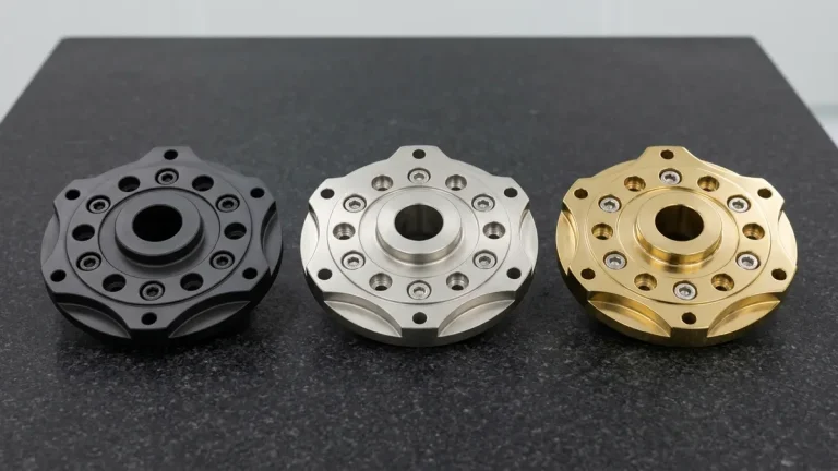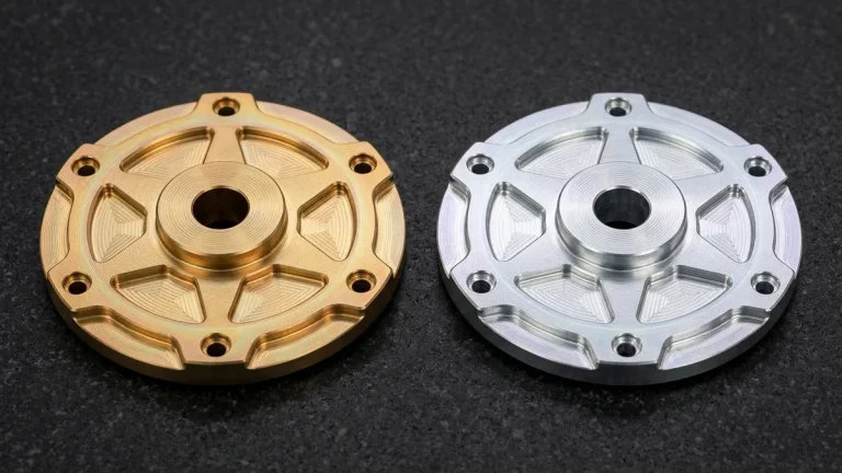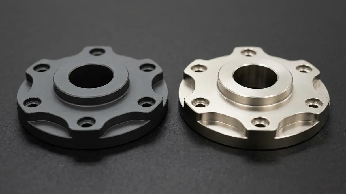
Evaluating electroplating vs anodizing is a critical Design for Manufacturability (DFM) decision whenever precision CNC machined components require enhanced wear resistance, corrosion barrier protection, or controlled electrical properties. Although both processes immerse metal workpieces into temperature-controlled chemical baths, their electrochemical growth mechanisms and dimensional impacts are fundamentally opposite.
Anodizing (MIL-A-8625 for aluminum and AMS 2488 for titanium) is an anodic conversion process where 50% of the oxide penetrates inward and 50% grows outward. Conversely, electrolytic plating (ASTM B633 / B841 zinc-nickel, ASTM B456 nickel-chrome, AMS 2460 hard chrome) and electroless nickel (ASTM B733 / AMS 2404) deposit metal 100% outward on the substrate.
At our Shenzhen CNC machining facility, our in-house engineering team programs pre-finishing toolpath offsets on high-speed 3-axis and 4-axis vertical machining centers (VMCs) and CNC turning centers. By calculating radial growth allowances and applying custom silicone masking before bath immersion, we hold final post-finish mating tolerances of ±0.010 mm to ±0.020 mm (±0.0004″ to ±0.0008″).
Executive Summary & Engineering Takeaways (BLUF)
- Dimensional Growth Asymmetry (50/50 vs. 100% Outward): MIL-A-8625 Type II (5–25 µm / 0.0002″–0.0010″) and Type III hardcoat anodizing (25–75 µm / 0.0010″–0.0030″) penetrate 50% inward and grow 50% outward (ΔDOD ≈ +1.0 × ttotal, ΔDID ≈ −1.0 × ttotal), whereas electroplating and ASTM B733 / AMS 2404 electroless nickel deposit 100% outward (ΔDOD = +2.0 × tcoat, ΔDID = −2.0 × tcoat).
- Surface Hardness & Sliding Wear Boundaries: Type III hardcoat anodizing on 6061-T6 or 7075-T651 reaches 400–550 HV (42–52 HRC equivalent), while heat-treated medium/high-phosphorus electroless nickel (ASTM B733 Class 2) reaches 850–1,000 HV (65–70 HRC) and industrial hard chrome reaches 850–1,100 HV (66–72 HRC) per ASTM E384.
- Throwing Power & Blind Bore Coverage: Electrolytic plating suffers from high-current edge buildup (“dog-boning” at 2.0×–3.0× nominal thickness) and Faraday cage starvation inside blind holes with L/D > 2.0; autocatalytic electroless nickel (ENP) maintains ±10% uniform thickness across deep internal passages.
- Electrical & Thermal Conductivity Contrast: Anodic aluminum oxide (Al2O3) is a crystalline ceramic insulator with a dielectric breakdown voltage exceeding 400 V/mil (16 V/µm), whereas nickel, silver, gold, and copper electroplatings provide low-resistance electrical continuity and RF shielding.
- Hydrogen Embrittlement Mitigation: High-strength alloy steels (4140, 4340, 17-4PH hardened ≥ 31 HRC or UTS ≥ 1,000 MPa / 145 ksi) electroplated in cathodic baths require mandatory relief baking at 190°C–220°C (375°F–425°F) for 3–24 hours initiated within 3 hours after plating per ASTM B850 and AMS 2460; anodizing generates oxygen at the anode and carries zero embrittlement risk.
Article Engineering Navigation
- 1. Electrochemical Conversion vs. Cathodic Deposition Physics
- 2. Dimensional Growth Equations, Faraday’s Law & Bore Allowance
- 3. Throwing Power, Faraday Cage Shielding & Edge Build-Up
- 4. Engineering Specification Matrix: Anodizing vs. Electroplating
- 5. Substrate Compatibility, Hydrogen Embrittlement & DFM SOP
- 6. Surface Finishing Defect Troubleshooting & DFM Matrix
- 7. When NOT to Choose Anodizing or Electroplating: Trade-Offs
- 8. Technical Engineering FAQ
1. Electrochemical Conversion vs. Cathodic Deposition Physics
To prevent tolerance stack-up failures and premature coating delamination, mechanical engineers must distinguish how atomic bond formation differs between anodic conversion and cathodic electrodeposition. While both belong to our precision surface finishes portfolio, their electrochemical cell polarities and mass-transfer mechanics operate in opposite directions.
A. Anodic Oxidation (MIL-A-8625 Type II & Type III Conversion)
In custom aluminum anodizing, the CNC-machined aluminum alloy workpiece (such as 6061-T6, 6082-T6, or 7075-T651) is wired as the positive anode (+) inside an agitated sulfuric or chromic acid electrolyte bath. Lead or aluminum sheets serve as the negative cathode (−) completing the direct-current (DC) circuit.
When DC current density of 1.2 to 3.5 A/dm2 (11 to 32 A/ft2) is applied across the cell, water molecules dissociate and liberate oxygen anions (O2−) at the submerged workpiece interface. These oxygen ions diffuse inward to react exothermically with aluminum cations (Al3+) from the parent metal lattice:
Because the aluminum substrate supplies the metal atoms that form the aluminum oxide (Al2O3) crystal lattice, the coating consumes base metal as it grows. In sulfuric acid baths (18°C–22°C / 64°F–72°F for Type II; 0°C–4°C / 32°F–39°F for Type III hardcoat), 50% of the coating thickness penetrates inward and 50% builds outward.
Because the Al2O3 layer is molecularly integrated with the base aluminum substrate, it exhibits zero peel or blister failure modes under shear loading. Before hydrothermal sealing in deionized water or nickel acetate at 96°C–98°C (205°F–208°F), its nanoporous hexagonal cell structure readily absorbs organic dyes or PTFE lubricants.
B. Cathodic Electrodeposition (Electrolytic Metal Plating)
In conventional electroplating (including ASTM B633 zinc, QQ-N-290 / AMS 2403 electrolytic nickel, ASTM B456 nickel-chromium, ASTM B650 hard chrome, and MIL-DTL-45204 gold), the workpiece is connected as the negative cathode (−). The electrolyte solution contains dissolved metallic salts of the target coating metal alongside soluble or inert anodes (+).
Under an applied external DC potential, positively charged metal cations (Mn+) migrate through the agitated bath along electric field lines toward the negatively charged workpiece surface. Upon reaching the cathode boundary layer, these dissolved cations accept electrons and reduce into a continuous crystalline metallic film:
Unlike anodizing, electrodeposition does not consume the parent metal; 100% of the plated thickness stacks directly on top of the original machined surface. Interfacial adhesion depends on chemical cleanliness, acid micro-etching, and intermediate strike layers—such as a Woods nickel strike on stainless steel or a double-zincate immersion layer (ASTM B253) on aluminum.
C. Autocatalytic Electroless Nickel Plating (ENP per ASTM B733 / AMS 2404)
To overcome the electric-field non-uniformity of electrolytic baths, electroless nickel plating (ENP) eliminates external DC rectifiers altogether. Instead, submerged parts undergo an autocatalytic chemical reduction driven by sodium hypophosphite (NaH2PO2) in a heated bath maintained at 85°C to 92°C (185°F to 198°F):
Every surface wet by the solution deposits a dense Nickel-Phosphorus (Ni-P) alloy at a uniform rate of 12 to 20 µm/hr (0.0005″ to 0.0008″/hr). High-phosphorus ENP (10%–13% P) forms an amorphous, non-magnetic metallic glass structure with exceptional resistance to chlorides and sour gas corrosion.
2. Dimensional Growth Equations, Faraday’s Law & Bore Allowance
When machining precision bearing housings, valve spools, and threaded standoffs on 3-axis and 4-axis VMCs or CNC turning centers, failing to account for coating buildup guarantees assembly interference. General unplated features default to ISO 2768-mK, whereas critical press-fit bores and dowel pin holes require tight tolerances of ±0.010 mm to ±0.020 mm (±0.0004″ to ±0.0008″).
A. Faraday’s Law of Electrolysis & Deposition Thickness
For both cathodic electroplating and anodic oxide conversion, the theoretical local coating thickness tcoat (measured in µm) accumulated over bath immersion time t is governed by Faraday’s Law of Electrolysis, scaled by the electrochemical cathode or anode current efficiency η of the specific bath chemistry:
tcoat = (η × I × t × M × 104) ÷ (n × F × A × ρ)
- tcoat: Resulting local coating thickness (µm; divide by 25.4 for thou / mils).
- η: Electrochemical current efficiency (dimensionless; ~0.92–0.96 for Watts nickel, ~0.15–0.22 for hexavalent hard chrome).
- I: Applied direct current (Amperes, A) and A: Active wetted surface area (cm2), where local current density J = I ÷ A.
- t: Immersion duration (seconds, s) and M: Atomic or molar weight of deposited species (g/mol; e.g., 58.69 g/mol for Ni).
- n: Valence electrons transferred per ion (e.g., n = 2 for Ni2+, n = 6 for Cr6+) and F: Faraday’s constant (96,485 C/mol).
- ρ: Coating mass density (g/cm3; e.g., 8.90 g/cm3 for pure nickel, ~7.85 g/cm3 for high-P ENP, ~3.10 g/cm3 for porous Type III Al2O3).
B. Pre-Finishing Bore, Shaft & Pitch Diameter Compensation Formulas
Let kout represent the outward growth fraction per surface relative to total coating thickness tcoat. For MIL-A-8625 Type II and Type III anodizing, kout = 0.5 (since 50% grows inward and 50% builds outward). For all electroplating and electroless nickel plating processes, kout = 1.0 (100% outward buildup).
Because cylindrical features experience coating buildup on two diametrically opposed walls simultaneously, the required pre-finishing CNC machined internal bore diameter Dmachined, external shaft diameter dmachined, and ISO 68-1 60° thread pitch diameter shift Δd2 = 4 × tout (where tout = kout × tcoat) are defined by:
1. Internal Bore Shift & Pre-Machining Target: ΔDID = −2 × kout × tcoat | Dmachined = Dfinal + (2 × kout × tcoat)
2. External Shaft Shift & Pre-Machining Target: ΔDOD = +2 × kout × tcoat | dmachined = dfinal − (2 × kout × tcoat)
3. ISO 68-1 60° Thread Pitch Diameter Shift (1 ÷ sin 30° = 2): Δd2(single) = 4 × tout = 4 × kout × tcoat (2·ttotal anodize vs. 4·tcoat plated) | Δd2(mated pair) = 8 × tout = 8 × kout × tcoat (4·ttotal anodize vs. 8·tcoat plated)
Worked Shop-Floor Calculation Example (⌀20.000 mm H7 Bearing Bore): Suppose an engineering drawing specifies a final post-finish bearing bore of ⌀20.000 mm H7 (+0.021 / −0.000 mm, or ⌀0.7874″ +0.0008″ / −0.0000″), corresponding to a final limit window of ⌀20.000–20.021 mm and a mean target of Dfinal = 20.0105 mm (0.7878″):
- Case A — 50 µm (0.0020″) MIL-A-8625 Type III Hardcoat Anodize (kout = 0.5): Each bore wall grows outward by 0.5 × 50 µm = 25 µm (0.025 mm / 0.0010″), shrinking the bore diameter by 0.050 mm (0.0020″). The pre-anodize CNC boring bar must over-cut the hole to ⌀20.050–20.071 mm (⌀0.7894″–0.7902″), with a mean target of Dmachined = 20.0105 + (2 × 0.5 × 0.050) = 20.0605 mm ±0.010 mm (0.7898″ ±0.0004″).
- Case B — 25 µm (0.0010″) ASTM B733 / AMS 2404 High-Phosphorus ENP (kout = 1.0): Each bore wall grows outward by 1.0 × 25 µm = 25 µm (0.025 mm / 0.0010″), also shrinking the bore diameter by 0.050 mm (0.0020″). The pre-plate CNC boring bar must finish the hole to ⌀20.050–20.071 mm (⌀0.7894″–0.7902″), with a mean target of Dmachined = 20.0105 + (2 × 1.0 × 0.025) = 20.0605 mm ±0.010 mm (0.7898″ ±0.0004″). Notice that a 50 µm Type III hardcoat and a 25 µm ENP layer require the exact same 0.050 mm (0.0020″) diametral bore over-cut!
3. Throwing Power, Faraday Cage Shielding & Edge Build-Up
In production DFM reviews, the most frequent cause of post-plating dimensional rejection is non-uniform current distribution across complex 3D part geometries. Because electrolytic plating relies on an external electric field between the anode and cathode, current density J concentrates heavily on protruding sharp corners while starving deep internal recesses.
At sharp external 90° edges with corner radii smaller than 0.5 mm (0.020″), electrostatic field lines crowd together, elevating local current density to 200%–300% of the nominal bath average. This creates localized excess plating thickness known as edge build-up or “dog-boning”, which rounds over crisp chamfers and causes interference on mating shoulders.
Conversely, when electrolytic plating is attempted on deep blind bores, narrow slots, or cross-drilled fluid galleries with a depth-to-diameter aspect ratio exceeding L/D > 2.0, the outer entrance rim acts as an electrostatic Faraday cage. Almost no metal ions deposit at the bottom of the bore, leaving internal walls bare and vulnerable to corrosion.
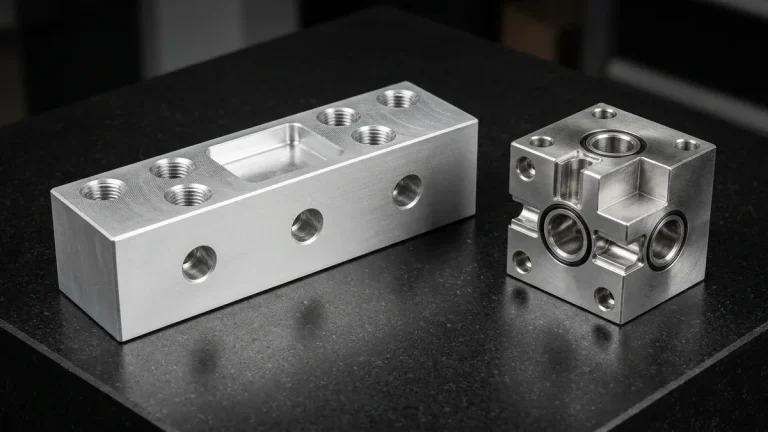
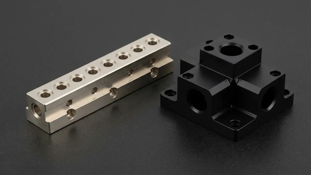
To prevent Faraday cage starvation inside multi-port blocks, we specify autocatalytic electroless nickel plating (ASTM B733) for brass or steel and sulfuric anodizing for aluminum. Below, the electroless nickel plated C3604 brass 8-port linear manifold rail and matte black anodized 6061-T6 aluminum orthogonal sensor manifold block show uniform coverage across spotfaced ports, 45° chamfers, and cross-drilled channels.
4. Engineering Specification Matrix: Anodizing vs. Electroplating
Selecting the optimal finish requires balancing substrate metallurgy, coating thickness, Vickers microhardness (per ASTM E384), neutral salt spray endurance (per ASTM B117), electrical contact resistance, and relative processing cost. The specification matrix below summarizes the seven primary electrochemical surface treatments executed across our in-house surface finishing lines.
| Finishing Process & Standard | Compatible Base Substrates | Typical Film Thickness | Outward Growth (kout per side) | Microhardness (ASTM E384) | Salt Spray (ASTM B117) & Conductivity | Recommended Application / When to Choose |
|---|---|---|---|---|---|---|
| Sulfuric Anodize (MIL-A-8625 Type II) | Aluminum alloys (6061, 6082, 7075, 5052) | 5 – 25 µm (0.0002″ – 0.0010″) | 50% Outward (0.5 × tcoat) | 250 – 350 HV (~25 – 36 HRC) | 336+ hrs sealed; Dielectric Insulator | Choose for cosmetic & corrosion-resistant aluminum brackets, optical mounts, and dyed housings (1.0x baseline cost index). |
| Hardcoat Anodize (MIL-A-8625 Type III) | Wrought Aluminum (6061-T6, 7075-T651) | 25 – 75 µm (0.0010″ – 0.0030″) | 50% Outward (0.5 × tcoat) | 400 – 550 HV (~42 – 52 HRC) | 500 – 1,000+ hrs; Insulator (>1,000 V) | Choose for high-wear sliding aluminum pistons, pneumatic cylinders, timing pulleys, and rotary flanges (1.6x–2.2x cost index). |
| Titanium Anodize (AMS 2488 Type II / III) | Titanium alloys (Ti-6Al-4V Grade 5, Grade 2) | 15–150 nm (0.59–5.91 µin, Type III); 1.0 – 2.5 µm (Type II) | Zero macro change (< 0.5 µm shift) | 380 – 450 HV (Anti-galling oxide) | 1,000+ hrs; Semiconductive | Choose for anti-galling orthopedic bone screws, medical surgical instruments, and aerospace titanium fasteners (1.8x–2.5x index). |
| Electroless Nickel (ASTM B733 / AMS 2404) | Steel (4140, 1045), Stainless, Aluminum, Brass | 7 – 50 µm (0.0003″ – 0.0020″) | 100% Outward (1.0 × tcoat) | 500 HV as-plated; 850 – 1,000 HV baked | 1,000+ hrs (High-P); Conductive Metal | Choose for complex multi-port manifolds, deep blind bores (L/D > 2), and precision steel shafts requiring uniform buildup (1.8x–2.8x index). |
| Zinc & Zinc-Nickel (ASTM B633 / B841) | Carbon & Alloy Steels (1045, 4140, SPCC) | 5 – 15 µm (0.0002″ – 0.0006″) | 100% Outward (1.0 × tcoat) | 120 – 250 HV (Sacrificial barrier) | 96 – 240 hrs (Zn); 720+ hrs (Zn-Ni) | Choose for economical sacrificial corrosion protection on structural steel brackets, chassis mounts, and threaded studs (0.9x–1.4x index). |
| Industrial Hard Chrome (AMS 2460 / ASTM B650) | Alloy & Tool Steels (4140, 4340, D2, 17-4PH) | 20 – 125 µm (0.0008″ – 0.0050″) | 100% Outward (1.0 × tcoat + grind) | 850 – 1,100 HV (~66 – 72 HRC) | 200 – 500 hrs; Conductive Metal | Choose for heavy-duty hydraulic piston rods, guide pins, and injection mold cores subjected to severe abrasive sliding wear (2.5x–3.5x index). |
| Gold / Silver Plating (MIL-DTL-45204 / B700) | Copper (C11000), Brass (C3604), Aluminum (over Ni) | 0.8 – 5.0 µm (30 – 200 µin) | 100% Outward (plus 3–5 µm Ni underplate) | 130 – 200 HK25 / HV (Hard gold Grade C) | Zero tarnish (Au); Ultra-Low Resistance | Choose for high-frequency RF waveguide cavities, electrical busbars, and low-contact-resistance connector pins (3.0x–6.0x index). |
5. Substrate Compatibility, Hydrogen Embrittlement & DFM SOP
A frequent pitfall in multi-material hardware assemblies is specifying anodizing on parts that contain non-aluminum inserts or impure casting alloys. In sulfuric acid anodizing tanks, only valve metals capable of forming a self-passivating barrier oxide—specifically aluminum, titanium, magnesium, and niobium—can serve as the anode.
If a CNC-machined 6061-T6 housing has stainless steel helicoils, pressed steel dowel pins, or brass inserts installed before anodizing, the electrical current channels entirely through the lower-resistance steel or brass. This violently dissolves the non-aluminum insert within minutes and burns the surrounding aluminum bore.
Similarly, alloy composition dictates anodic oxide clarity and density. Wrought 6061-T6 and 6082-T6 produce uniform, clear oxides ideal for bright Type II dyeing, whereas high-zinc 7075-T651 exhibits a slight bronze tint under thick Type III hardcoat, and high-silicon die-cast alloys (A380 or ADC12 with 8%–12% silicon) turn mottled gray because silicon crystals resist anodizing.
Hydrogen Embrittlement (HE) Relief Protocol on High-Strength Steels
When electroplating high-strength alloy steels hardened to ≥ 31 HRC (tensile strength ≥ 1,000 MPa / 145 ksi, such as quenched-and-tempered 4140, 4340, or 17-4PH H900), atomic hydrogen (H0) generated during acid pickling and cathodic deposition diffuses into grain boundaries. Under tensile service loads, this trapped hydrogen causes sudden, catastrophic intergranular fracture.
To prevent hydrogen embrittlement, our finishing line enforces two mandatory thermal treatments per ASTM B850, AMS 2460, and ASTM F519: first, pre-plate stress-relief baking at 190°C–220°C (375°F–425°F) after machining or grinding; second, post-plate hydrogen effusion baking at 190°C–220°C (375°F–425°F) for 3 to 24 hours (8–24 hours per ASTM B850) initiated within 3 hours after plating.
4-Step Shop-Floor DFM SOP for Pre-Finishing CNC Machining
- Break Sharp External Corners to Prevent Coating Spalling & Dog-Boning: Program 3-axis and 4-axis VMC finishing toolpaths to machine a minimum edge radius of R0.4 mm to R0.8 mm (0.016″ to 0.031″) on all external edges. Because anodic Al2O3 grows perpendicular to the substrate surface, a razor-sharp 90° corner creates a V-shaped void at the vertex where Type III hardcoat cracks and spalls under light contact.
- Selectively Mask or Over-Machine Tight-Tolerance Bearing Bores & Threads: For H7 bearing seats and dowel pin holes held to ±0.010 mm (±0.0004″), either apply the Dmachined radial compensation offset prior to bath immersion or seal the bore using CNC-turned silicone expander plugs and chemical-resistant masking tape so the mating journal remains bare machined metal.
- Design Dedicated Racking & Electrical Contact Locations: Every anodized or rack-plated component requires a secure mechanical clamping point for titanium anodizing fingers or copper plating hooks. Specify non-critical internal tapped holes, sacrificial mounting tabs, or non-cosmetic rear faces on the 2D drawing where small 0.5–1.5 mm (0.020″–0.060″) bare contact witness marks are permissible.
- Verify Post-Finish Coating Thickness & Datum Geometry Before Shipment: After sealing or hydrogen relief baking inside our 20°C ± 1°C climate-controlled metrology room, our engineers verify non-conductive anodic film thickness using eddy-current probes (ISO 2360), metallic plating thickness via XRF analysis, and critical bore tolerances using a Zeiss bridge CMM (available upon request), 3-point internal bore micrometers, and Go/No-Go plug and thread gauges.
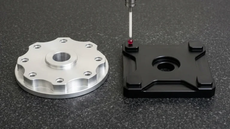
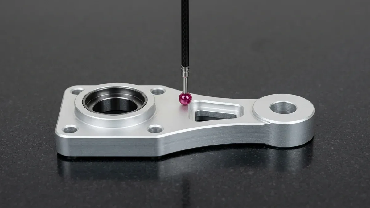
In the inspection setup below, a CNC-milled 6061-T6 aluminum dog-bone twin-bore bearing carrier link plate—finished in matte clear silver anodize with a selectively masked bare-metal internal bearing seat—rests flat on a black granite surface plate while a vertical bridge CMM ruby ball probe verifies the top horizontal datum plane.
6. Surface Finishing Defect Troubleshooting & DFM Matrix
Even when a base component is machined within print tolerance on a 3-axis VMC or lathe, improper pre-treatment chemistry, blind-hole acid entrapment, or uncompensated thread geometry can scrap an entire batch during finishing. Table 2 outlines the six most common finishing defects and the exact shop-floor DFM countermeasures we implement.
| Observed Defect Mode | Affected Process | Physical & Electrochemical Root Cause | Shop-Floor Corrective Action | Recommended Application / When to Choose |
|---|---|---|---|---|
| Bearing Bore Seizure / Press-Fit Interference | Type III Hardcoat & ENP Plating | Machining bore to final nominal diameter before applying 25–50 µm (0.0010″–0.0020″) coating shrinks ID by 0.050 mm. | Over-bore ID by 2 × kout × tcoat during CNC rough/finish boring or mask bore with tapered silicone plugs. | Choose pre-machining offset for wear sleeves; choose silicone plugging when ±0.010 mm (±0.0004″) bare-metal fit is required. |
| Thread Binding & GO-Gauge Failure | Electrolytic Plating, ENP & Type III | 60° thread flank geometry (1 ÷ sin 30° = 2) amplifies outward growth on pitch diameter by Δd2 = 4·kout·tcoat per thread (2·ttotal anodize vs. 4·tcoat plated) or 8·kout·tcoat across a mated pair (4·ttotal anodize vs. 8·tcoat plated). | Use oversized H-limit taps (6G / 6H+0.05 mm) before plating or plug tapped holes with reusable silicone thread screws. | Always mask M2–M6 fine threads during Type III hardcoat; use pre-plate oversized taps for high-volume zinc-plated steel nuts. |
| Acid Bleed-Out & White Corrosion Staining | Type II & Type III Sulfuric Anodize | Sulfuric electrolyte trapped inside blind holes (L/D > 4), spot-welded lap joints, or porous castings leaches out after sealing. | Add ⌀2.0–3.0 mm (0.080″–0.120″) cross-drainage vent holes, apply ultrasonic deionized rinsing, or switch to Type I chromic anodize. | Specify through-drilled drainage passages on all submerged fluid manifolds and robotic structural housings. |
| Corner Micro-Cracking & Edge Spalling | Type III Hardcoat Anodizing (≥ 50 µm) | Columnar Al2O3 crystals grow outward normal to flat faces, opening a brittle V-fissure along sharp 90° edges. | Machine continuous tangential corner radii of R0.5–R1.0 mm (0.020″–0.040″) on all external load-bearing edges. | Mandatory on dynamic hydraulic spools, wear plates, and hard-anodized 7075-T651 gears and splines. |
| Coating Blistering & Interfacial Peeling | Electroless Nickel & Chrome on Aluminum | Instantaneous native oxide reformation on aluminum prevents direct metallic bonding if zincate activation is incomplete. | Execute double-zincate immersion treatment per ASTM B253 followed by an alkaline electroless nickel strike and adhesion bake. | Choose double-zincate ENP whenever aluminum electronics enclosures or connectors require solderability or EMI shielding. |
| Catastrophic Dissolution of Steel Inserts | Sulfuric & Hardcoat Anodizing | Pre-installed stainless helicoils, PEM studs, or steel dowel pins act as low-resistance anodes and dissolve in sulfuric acid. | Sequence hardware assembly strictly AFTER anodizing and sealing, or encapsulate non-removable inserts in liquid plastisol maskant. | Always specify “Install Helicoils / Dowel Pins After Anodizing” in the assembly notes of your 2D engineering drawing. |
7. When NOT to Choose Anodizing or Electroplating: Trade-Offs
No single electrochemical surface treatment is universally superior across all mechanical, thermal, and electrical operating environments. Before locking in a final 2D drawing callout for electronic appliance enclosures, high-cycle robotic actuators, or hydraulic fluid valves, hardware engineers should carefully evaluate the following substrate and geometry disqualifiers:
- When NOT to Choose Anodizing:
- Ferrous Steels, Copper, or Brass Substrates: Anodizing is physically limited to aluminum, titanium, and magnesium. Carbon steels (1045, 4140), stainless steels (304, 316L, 17-4PH), and brass (C3604) must use electroplating, ENP, passivation (ASTM A967), or black oxide.
- Full-Surface Electrical Grounding & EMI/RFI Shielding: Because Type II and Type III Al2O3 coatings are electrical insulators (> 400 V/mil dielectric breakdown), unmasked anodized chassis flanges cannot conduct EMI ground currents. Choose trivalent chromate conversion (MIL-DTL-5541 Type II Class 3 / SurTec 650, dried strictly ≤ 60–65°C, contact resistance < 5,000 µΩ/in2) or electroless nickel plating instead.
- High Point-Load Impact on Soft Aluminum (“Eggshell Effect”): Although Type III hardcoat reaches 500 HV, it is a thin, brittle ceramic resting on a softer 6061-T6 core (~107 HV). Under concentrated Hertzian point impact (such as ball-bearing brinelling), the aluminum substrate yields underneath and cracks the anodic layer.
- Extreme Alkaline Environments (pH > 8.5): Aluminum oxide dissolves rapidly in strong caustic/alkaline washdown solutions; high-phosphorus ENP (ASTM B733) is far superior for caustic chemical resistance.
- When NOT to Choose Electrolytic Plating:
- Deep Blind Bores, Internal Labyrinths & Micro-Channels (L/D > 2.0): Standard electrolytic nickel, chrome, or zinc cannot penetrate deep internal cavities due to Faraday cage shielding. Specify autocatalytic electroless nickel (ENP) or anodizing instead.
- Ultra-High-Strength Steels (> 48 HRC / > 1,500 MPa) Critical to Fatigue: Even with post-plate baking, cathodic electroplating on ultra-high-tensile springs or aerospace bolts carries residual hydrogen embrittlement risk; prefer PVD vacuum coatings or mechanical zinc plating (ASTM B695).
- Weight-Critical Aerospace & UAV Structural Brackets: On aluminum airframe components, MIL-A-8625 anodizing adds virtually zero mass while preserving substrate fatigue life, whereas thick metallic electroplating adds parasitic weight and can reduce aluminum high-cycle fatigue strength by 15%–30%.
For production scheduling, our Shenzhen facility delivers as-machined CNC prototypes in 4–8 business days (Ex-Factory Production & Inspection Turnaround). Prototypes requiring MIL-A-8625 anodizing, selective masking, or ASTM B733 electroless nickel ship in 7–12 business days Ex-Factory (production batches in 7–30 business days), decoupled from 3–5 business days international air transit (DHL/FedEx/UPS).
🔗 Related Surface Finishing & Coating Engineering Guides
8. Technical Engineering FAQ
Anodizing per MIL-A-8625 penetrates 50% inward into the aluminum lattice and builds 50% outward, shrinking an internal bore diameter by 1.0 times the total film thickness. Conversely, electroplating and ASTM B733 electroless nickel deposit 100% outward, shrinking internal bore diameters by 2.0 times the specified coating thickness.
Autocatalytic electroless nickel plating (ASTM B733) provides superior ±10% thickness uniformity inside deep blind bores exceeding L/D of 2.0 because chemical reduction proceeds without external electric fields. Electrolytic plating suffers from Faraday cage shielding in recessed cavities, requiring oversized pre-plate taps or selective plugging to prevent thread binding.
No, ferrous steels (such as 4140 or 304 stainless) and copper alloys (C3604 brass) cannot undergo sulfuric acid anodizing because their metal ions dissolve rapidly in the anodic electrolyte. These substrates require electrolytic zinc, hard chrome, or autocatalytic electroless nickel plating for wear and corrosion protection.
Hydrogen embrittlement relief baking per ASTM B850 is mandatory whenever high-strength steels hardened at or above 31 HRC (≥ 1,000 MPa / 145 ksi) undergo acid pickling and cathodic electroplating. Parts are baked at 190–220°C (375–425°F) for 3 to 24 hours within 3 hours after plating.
Ready to Optimize Your Custom Parts for Precision Manufacturing?
Upload your 3D CAD models (STEP/IGES) and 2D tolerance drawings for a comprehensive DFM review covering pre-finishing bore compensation, selective masking, and MIL-A-8625 or ASTM B733 surface treatment verification. Our engineering team ensures every critical bearing journal and threaded interface meets your exact assembly tolerances.
Request a Technical DFM & Custom Quote →