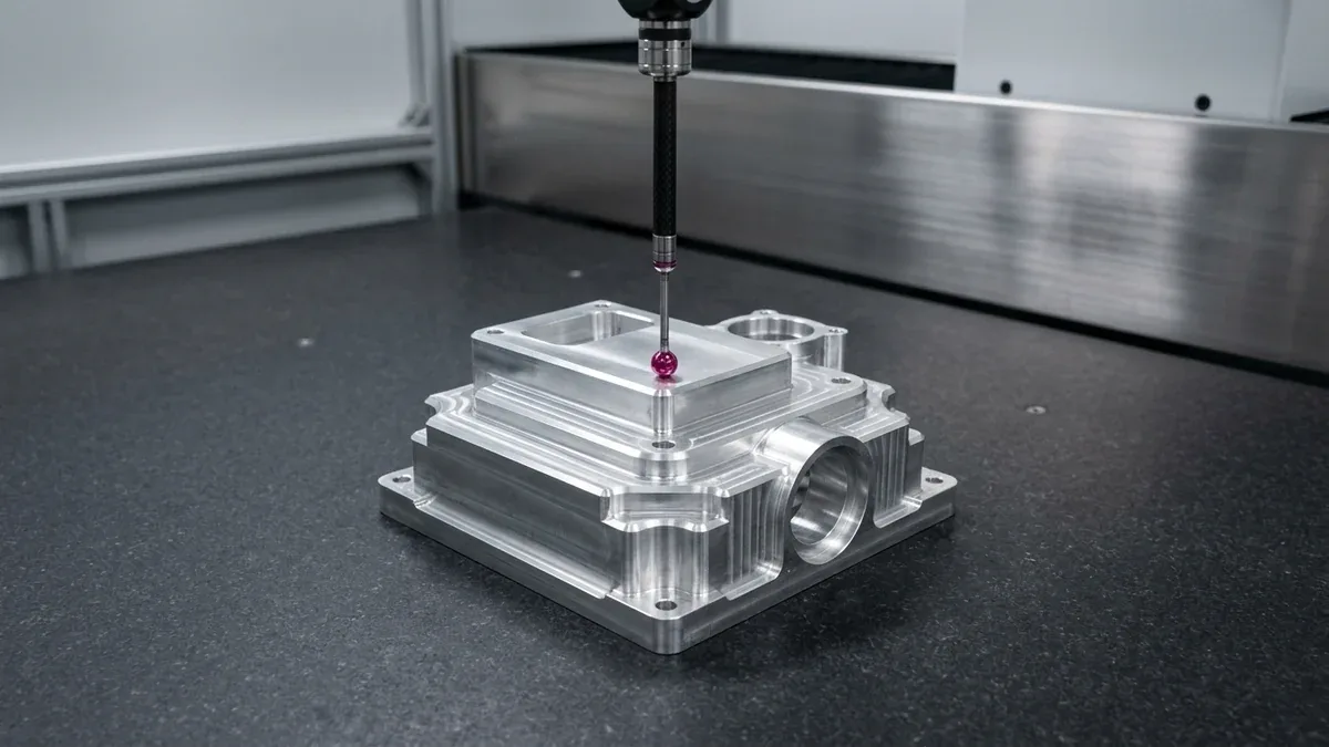
Precision CNC milling is an intricate equilibrium of cutting forces, thermal dissipation, harmonic dynamics, and metallurgical behavior. When cutting flight-critical aerospace structures, surgical implants, or high-tolerance optical housings, even minor process instabilities can manifest as visible surface blemishes, severe chatter waves, or out-of-tolerance dimensional failures. A ruined workpiece wastes expensive billet material, destroys premium carbide tooling, and threatens project milestones. In precision manufacturing, mastering cnc milling defects and solutions ensures repeatable dimensional stability and predictable production scaling.
At AS Prototypes, with over a decade of precision rapid prototyping and CNC manufacturing leadership in Shenzhen, our machine shop operates on zero-defect quality principles. Eliminating defects requires understanding their root physical mechanisms. In this comprehensive troubleshooting guide, our senior machining engineers dissect the five most prevalent CNC milling defects—chatter marks, clamping dents, thermal burns, burr formation, and tool deflection—and provide shop-proven countermeasures to ensure flawless, repeatable parts.
1. The 5 Most Common CNC Milling Defects & Root Causes
When an unpredicted defect appears on a machined workpiece, operators must distinguish between metallurgical, mechanical, and toolpath-induced root causes:
1. Clamping Dents and Fixturing Distortion
Dents or localized surface indentations frequently occur when machining soft, ductile alloys such as 6061-T6 aluminum, brass, bronze, or copper. This defect is driven by excessive, uncalibrated clamping pressure from pneumatic or hydraulic vise jaws. Furthermore, if the raw stock is clamped unevenly, the workpiece elastically deforms during machining; once the clamps are released, the part springs back into a distorted, out-of-flat geometry.
2. Chatter Marks & Harmonic Wave Patterns
Chatter manifests as regular undulating ripples, fish-scale waves, or dull, noisy witness marks across milled floors and vertical walls. Chatter is caused by regenerative vibration—a resonant feedback loop between the cutting tool, tool holder, spindle, and workpiece. Major contributors include excessive tool overhang (L/D > 4:1), improper spindle harmonics, a worn cutting edge, or an alternating climb-to-conventional toolpath.
3. Thermal Surface Burns & Local Discoloration
Brown, blue, or blackened heat-tinted bands along machined surfaces indicate extreme thermal spikes exceeding the material’s oxidation threshold. Thermal burns occur when the cutting tool rubs against the metal rather than cleanly shearing chips. This happens when the feed per tooth (fz) is set too low relative to the cutting speed (Vc), when tool flank wear is severe, or when coolant fails to penetrate deep pockets in heat-sensitive alloys like titanium (Ti-6Al-4V) or 316L stainless steel.
4. Heavy Burrs and Edge Flashing
Burrs are sharp, plastically deformed fins of unsevered material left clinging to edges after drilling or face milling. As the cutting tool exits the boundary of a ductile workpiece, the thin remaining wall lacks the mechanical rigidity to support shear cutting; instead, it rolls over in the direction of tool motion. Burrs pose severe assembly interference and safety hazards, demanding labor-intensive deburring.
5. Dimensional Taper & Wall Deflection (Overcut / Undercut)
When milling deep vertical walls, long-reach end mills experience lateral radial cutting forces (Fr). The tool pushes off away from the material, creating an unintended taper (undercut at the bottom). Conversely, when cutting internal pockets, cutter deflection in corners can cause the tool to pull into the cut, creating an irreversible gouge (overcut).
2. Troubleshooting Matrix: CNC Milling Defects, Causes & Solutions
The engineering reference table below provides quick diagnostics and actionable remedies for shop-floor troubleshooting:
| Defect Category | Visual / Physical Symptom | Root Cause Mechanism | Immediate Shop-Floor Remedy | Long-Term Preventive Measure |
|---|---|---|---|---|
| Clamping Dents | Depressions or crushed edges at vise contact points | Excessive hydraulic clamping force; localized high-pressure contact | Insert sacrificial aluminum shims; reduce hydraulic regulator pressure | Machine in-situ soft jaws contouring the part; deploy vacuum chuck fixtures |
| Chatter Marks | Ripples, scalloped surface waves, high Ra roughness | Regenerative vibration; long tool overhang; blunt cutter edge | Shorten tool gauge length; adjust spindle RPM by ±10% to find stable harmonic sweet spot | Adopt variable-pitch & variable-helix end mills; utilize hydraulic or shrink-fit chucks |
| Thermal Burns | Blue/straw discoloration, built-up edge (BUE), micro-cracks | Tool rubbing due to insufficient feed per tooth; dry cutting in titanium/stainless | Increase feed per tooth (fz); verify flood coolant nozzle alignment | Equip 70-bar Through-Spindle Coolant (TSC); apply TiAlN or DLC anti-friction coatings |
| Exit Edge Burrs | Sharp ragged metal flash along cut exit edges | Plastic deformation roll-over at boundary exit; dull cutting edge | Program chamfer toolpath along boundaries; replace worn cutters | Optimize CAM entry/exit angles (roll-in toolpaths); integrate vibratory mass finishing |
| Wall Taper Deflection | Non-perpendicular vertical walls; dimensional drift | Radial tool push-off under high radial engagement (ae) | Take a final spring pass (zero radial stepover) at light feed | Use high-rigidity carbide shank tools; transition to dynamic trochoidal milling toolpaths |
3. Optimizing Spindle Dynamics & Coolant Delivery
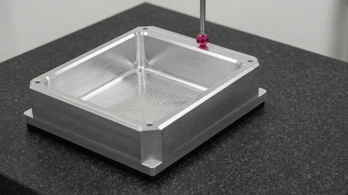
Preventing chatter and thermal burns requires strict CAM toolpath planning:
- Commit Exclusively to Climb Milling: In climb (down) milling, the cutter tooth enters with maximum chip thickness and exits at zero thickness, transferring cutting heat into the chip and away from the finished surface. In conventional (up) milling, the tooth rubs before shearing, accelerating tool flank wear and degrading surface finish.
- Dynamic Trochoidal Milling for Uniform Tool Load: Traditional 90° corner cuts spike tool engagement from 25% up to 100%, causing instant chatter and tool deflection. Dynamic toolpaths maintain a constant small radial engagement (ae = 8% – 15% D) with high axial depths, keeping cutting forces smooth and predictable.
- Temperature-Controlled Flood Coolant (20°C ± 1°C): Coolant temperature fluctuations cause workpiece thermal expansion drift. AS Prototypes equips CNC mills with closed-loop coolant temperature control to maintain thermal equilibrium throughout multi-hour roughing and finishing cycles.
4. Precision Deburring & Quality Control Protocols
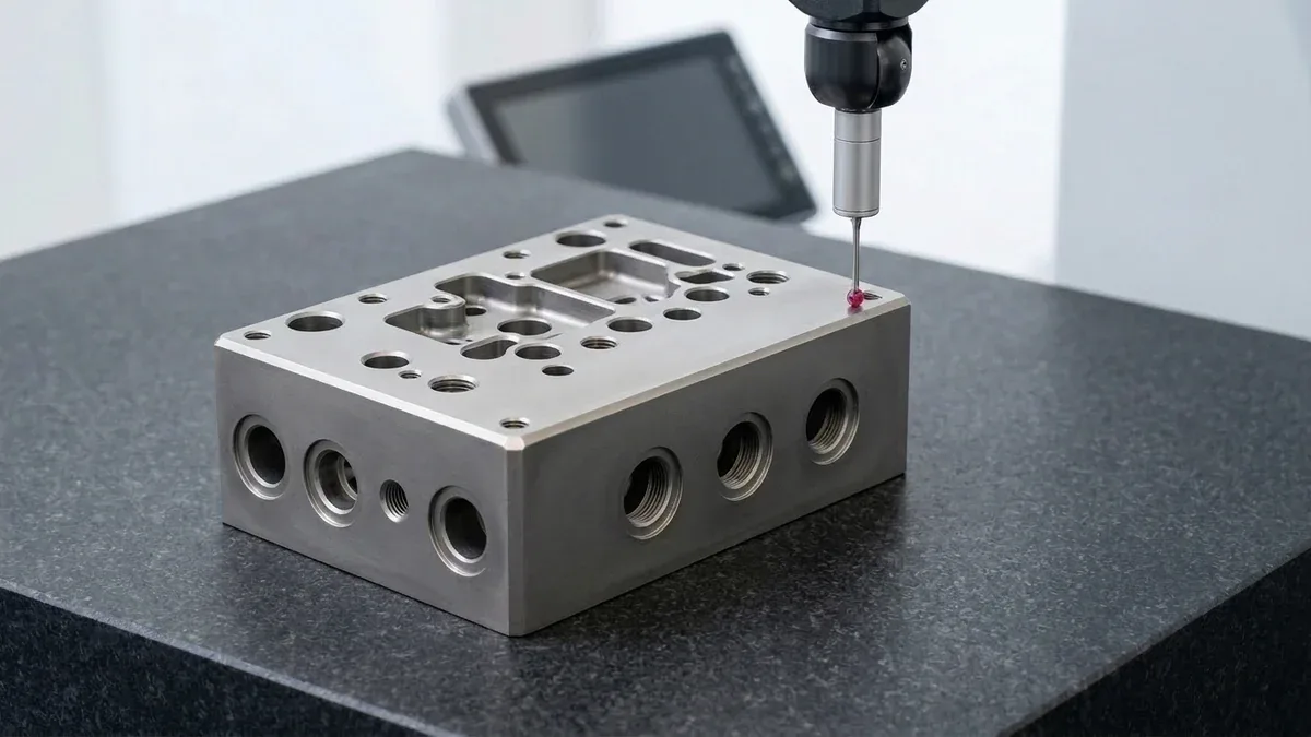
Burrs are not acceptable on precision medical or aerospace parts. Our quality assurance protocol incorporates a multi-tier deburring and metrology workflow:
- In-Process CNC Chamfering: Before a part is released from the vise, a dedicated 45° or 60° chamfer mill traces all profile edges to slice off burrs while the part is still rigidly referenced.
- Micro-Deburring Under Magnification: Experienced hand-finishers utilize specialized surgical micro-blades and ceramic stones under 10× optical magnification to break sharp micro-burrs in cross-drilled internal ports.
- CMM & Surface Profilometer Verification: Critical features are verified on programmable Zeiss bridge CMM machines (available upon request), 2.5D optical vision systems, and calibrated contact stylus profilometers (ISO 4287) to confirm that surface roughness (Ra 0.4 to 0.8 μm) and critical dimensional tolerances (±0.010 mm / ±0.0004″) comply with drawing specifications.
5. The AS Prototypes Quality Assurance Guarantee
By enforcing closed-loop process monitoring, rigid tool life management, custom fixturing design, and comprehensive quality assurance and dimensional inspection protocols, AS Prototypes eliminates manufacturing defects before parts ever ship to our international clients.
6. Technical Engineering FAQ
Chatter stems from dynamic resonance between tool natural frequency and spindle harmonics. Solutions include reducing overhang (L/D ≤ 3), employing variable-helix end mills, and shifting spindle speed into stable lobe zones.
Burrs occur when exiting tools push plastically deformed material outward. We program automated chamfer deburring passes using 90° helical chamfer mills and optimize climb milling paths so tools exit into solid stock.
Floor scallop unevenness results from cutter axial runout, tool deflection, or slight spindle misalignment. Applying dedicated spring passes with bull-nose or wiper end mills eliminates transition steps.
Partner with Our Precision CNC Machining & Engineering Team
Eliminate tool deflection, residual stress distortion, and tolerance stack-up risks before production begins. Upload your 3D CAD files (STEP/IGES) and 2D GD&T drawings for a comprehensive shop-floor DFM review and custom quotation.
Upload 3D CAD for Engineering DFM & RFQ