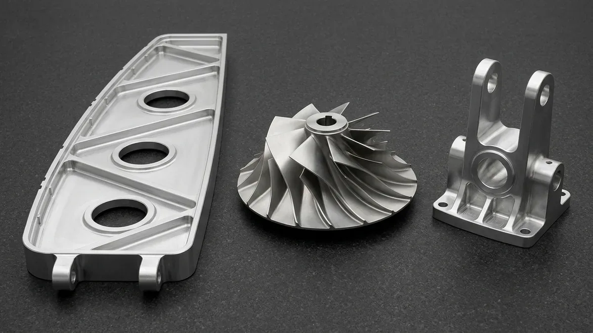
Modern aircraft development programs demand flight-ready hardware that survives extreme aerodynamic bending loads, high-frequency turbine vibration, and thermal cycling from −55 °C to +700 °C (−67 °F to +1,292 °F). Executing precision aviation CNC prototyping from wrought aerospace billets bridges the critical engineering gap between digital finite-element simulations and physical wind-tunnel, structural-rig, or iron-bird qualification testing.
Unlike polymer additive stand-ins with layer anisotropy, subtractive Computer Numerical Control (CNC) machining carves functional prototypes directly from traceable 7075-T7351, Ti-6Al-4V, and 15-5PH billets. Our in-house CNC machining facility integrates 3/4-axis Vertical Machining Centers (VMCs), simultaneous 5-axis CNC machining, cylindrical grinding, and 20 °C Coordinate Measuring Machine (CMM) verification for custom aerospace prototype manufacturing.
Executive Summary & Engineering Takeaways (BLUF)
- Alloy-to-Component Architecture: Specify over-aged 7075-T7351 (AMS 4045) for monolithic wing ribs and fuselage frames to prevent Stress Corrosion Cracking (SCC), Ti-6Al-4V Grade 5 (AMS 4928) for high-speed compressor blisks, 15-5PH H1025 (AMS 5659) for 35 MPa (5,000 psi) hydraulic manifolds, and 58–60 HRC 440C stainless steel for ground servo valve spools.
- Process & Tolerance Partitioning: General machined features follow ISO 2768-mK, critical bearing bores (H7) and clevis pin locations hold ±0.010 mm to ±0.020 mm (±0.0004″ to ±0.0008″) on 3/4/5-axis VMCs, and cylindrical-ground spool lands or Wire Electrical Discharge Machining (EDM) profiles achieve ±0.005 mm (±0.0002″).
- Thin-Wall & Airfoil Kinematics: Staggered 1-to-6 waterline step-down passes (axial depth ap ≤ 0.5 · tw) suppress cantilevers on 1.2 mm (0.047″) aluminum ribs, while circle-segment tapered barrel cutters expand 5-axis blade stepover by 3.4× over ball-nose tools at a 1.5 µm (59 µin) cusp limit.
- Surface Finishing & Ex-Factory Lead Times: Bare-metal CNC aviation prototypes ship ex-factory in 4 ~ 8 Business Days, surface-treated hardware (MIL-A-8625 Type II/III anodizing, MIL-DTL-5541 Type II SurTec 650, ASTM A967 passivation) ships in 7 ~ 12 Business Days, and complex 5-axis/low-volume runs ship in 7 ~ 30 Business Days (plus 3 ~ 5 Days air transit).
Article Engineering Navigation
- 1. Monolithic Airframe Hogouts: 7075-T7351 Airfoil Wing-Box Ribs and Wing-Spar Truss Struts
- 2. Why Do Thin-Wall 7075-T7351 Aviation Ribs Deflect During Pocket Milling?
- 3. Simultaneous 5-Axis Propulsion Prototyping: Ti-6Al-4V Blisks and 17-4PH Stator Rings
- 4. Flight-Control Hydraulics & Avionics Cooling: 15-5PH Manifolds, 440C Spools, and 6061 Cold Plates
- 5. Quantitative Derivation: 5-Axis Blade Scallop Cusp Height and Barrel-Cutter Stepover Math
- 6. Aviation Metrology, Datum-Locking Verification & Shop-Floor Failure Troubleshooting
- 7. Engineering Verdict: Selecting the Optimal Aviation Prototyping Architecture
- 8. Technical Engineering FAQ
1. Monolithic Airframe Hogouts: 7075-T7351 Airfoil Wing-Box Ribs and Wing-Spar Truss Struts
Monolithic airframe hogouts are single-piece structural components machined from pre-stretched wrought aluminum plate (7075-T7351 or 2024-T351) with 85%–94% volumetric chip removal, holding ±0.010 mm (±0.0004″) tolerances and Ra 0.8 µm (32 µin) finishes. Consolidating riveted sheet assemblies into one billet part eliminates fastener mass, though deep pockets require strict Design for Manufacturability (DFM) controls.
Legacy aircraft construction required stamping dozens of sheet webs and driving hundreds of rivets per rib. Modern fixed-wing, regional electric aircraft, and electric vertical takeoff and landing (eVTOL) programs replace built-up assemblies with monolithic billet hogouts (as shown in the 7075-T7351 airfoil wing-box rib hogout and wing-spar X-truss strut below).
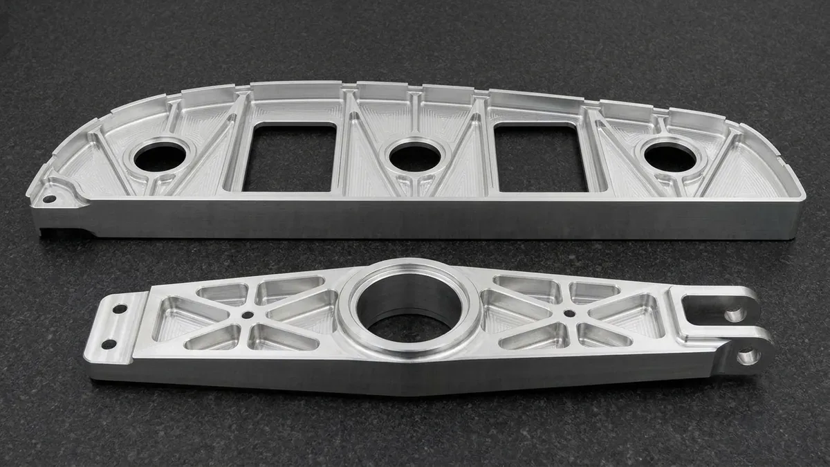
Component Anatomy & Process Routing in Figure 1
Understanding the structural load path and machine-tool assignment for each airframe geometry prevents unnecessary 5-axis cost inflation while preserving flight-critical Geometric Dimensioning and Tolerancing (GD&T) datums:
- 7075-T7351 Wide-Chord Airfoil Wing-Box Rib Hogout (Figure 1, Top): Spanning 600 to 1,600 mm (23.6″ to 63.0″) in chord length on commercial, regional electric, and commuter aircraft wings, this monolithic rib maintains the aerodynamic airfoil camber while transferring distributed skin pressure loads into the front and rear wing spars. Its outer perimeter forms a standing 18–28 mm (0.71″–1.10″) Outer Mold Line (OML) skin-attachment flange with periodic castellated stringer cutout notches (“mouseholes”) along the upper camber rim so longitudinal wing-skin stringers pass continuously through the rib. Inside the perimeter rim, integral diagonal Warren-truss and vertical blade stiffeners (1.2–1.5 mm / 0.047″–0.059″ thick) frame a recessed 1.5 mm horizontal diaphragm web pierced by two rectangular wing-battery module bays, three circular flanged lightening apertures with raised reinforcing collars that prevent local web shear buckling, and a leading-edge spar shear-tie lug. Ribs with orthogonal 90° flanges are rough- and finish-milled on 3-axis bed mills with vacuum grid fixtures, whereas ribs with variable compound bevel angles matching a tapered wing loft undergo 5-axis swarf milling along the outer skin land.
- 7075-T7351 Wing-Spar X-Truss Strut & Shear-Tie Clevis Fitting (Figure 1, Bottom): Engineered to transfer concentrated actuator, landing-gear, or wing-to-fuselage shear loads into the primary spar web, this monolithic strut integrates radial X-truss triangular weight-relief pockets (R 5.0 mm / 0.197″ internal corner radii) that maximize torsional rigidity per gram. The central cylindrical boss houses a precision-bored Ø32 mm H7 (+0 / +0.025 mm) spherical bearing seat with a stepped locating shoulder for flight-control rod routing, while the right-hand twin-ear clevis fork holds ±0.010 mm (±0.0004″) coaxiality across opposing pin bores and the left-hand flange provides a 4-hole spar-cap bolt pattern. Because all pocket walls, bearing bosses, and floor webs lie orthogonal to the primary XY datum plane with side-indexed clevis bores, our shop machines this component on high-speed 3-axis and 4-axis CNC milling centers (Brother and Makino VMCs) using precision machine vises for Op10 and custom-contoured aluminum soft jaws for Op20.
| Aerospace Alloy & Spec | Tensile / Yield Strength (MPa / ksi) | Machinability & SCC Resistance | Relative Machining Cost Ratio | Achievable Feature Tolerance (mm / in.) | Recommended Application / When to Choose |
|---|---|---|---|---|---|
| 6061-T651 Aluminum (AMS 4027) | 310 / 276 MPa (45.0 / 40.0 ksi) | 85% rating; high corrosion & SCC resistance; weldable | 1.0x (Baseline) | ±0.010 mm (±0.0004″) | Best for conduction-cooled avionics heatsinks, cockpit housings, and Alpha form-and-fit prototypes |
| 7075-T7351 Aluminum (AMS 4045) | 505 / 435 MPa (73.2 / 63.1 ksi) | 70% rating; high SCC immunity in thick plate; non-weldable | 1.3x | ±0.010 mm (±0.0004″) | Best for monolithic wing rib truss struts, thick fuselage bulkhead frames, and hydraulic manifold brackets |
| 2024-T351 Aluminum (AMS 4037) | 470 / 325 MPa (68.2 / 47.1 ksi) | 70% rating; superior cyclic fatigue crack arrest; needs anodizing | 1.35x | ±0.012 mm (±0.0005″) | Best for tension-loaded lower wing skins, fuselage shear ties, and high-cycle vibration links |
| 15-5PH / 17-4PH Steel (AMS 5659 / 5643) | 1,170 / 1,070 MPa (170 / 155 ksi, H1025) | 45% rating; transverse toughness (15-5PH); high SCC resistance | 2.2x | ±0.010 mm (±0.0004″) | Best for 35 MPa flight-control hydraulic manifolds (15-5PH) and turbine stator casing rings (17-4PH) |
| 440C Stainless Steel (AMS 5630, 58–60 HRC) | 1,965 / 1,895 MPa (285 / 275 ksi) | 30% annealed turn; requires post-HT cylindrical grinding | 2.8x | ±0.005 mm (±0.0002″ ground) | Best for wear-resistant hydraulic servo valve spools, fuel metering sleeves, and actuator bearing races |
| Ti-6Al-4V Grade 5 (AMS 4928) | 950 / 880 MPa (138 / 128 ksi) | 22% rating; 6.7 W/m·K thermal conductivity; needs 70-bar TSC | 3.4x | ±0.010 mm (±0.0004″) | Best for 5-axis centrifugal compressor blisks, engine pylon mounts, and carbon-composite mating fittings |
When to Avoid Peak-Aged 7075-T651 in Thick Monolithic Airframes
Although peak-aged 7075-T651 provides 572 MPa (83.0 ksi) tensile strength, engineers must avoid specifying T651 for thick monolithic bulkheads (> 25 mm / 1.0″) where deep pocketing exposes short-transverse grains to sustained preload. In humid or altitude-condensation service, peak-aged 7075-T651 is highly susceptible to intergranular Stress Corrosion Cracking (SCC).
Specifying the over-aged 7075-T7351 temper stabilizes grain-boundary precipitates and eliminates SCC risk while retaining 505 MPa (73.2 ksi) tensile strength. In addition, 7075 alloys must never be fusion arc-welded due to severe solidification micro-cracking in the zinc-magnesium-copper matrix; assemblies requiring welded ducting or brackets must switch to 6061-T6 or formed 5052-H32 aerospace sheet metal fabrication.
2. Why Do Thin-Wall 7075-T7351 Aviation Ribs Deflect During Pocket Milling?
Thin-wall 7075-T7351 aviation ribs deflect during CNC pocket milling when radial cutting forces (Fr) act against an unsupported cantilever web (tw ≤ 1.5 mm / 0.059″), causing elastic wall spring-back, tapered cross-sections exceeding 0.08 mm (0.0031″), and regenerative harmonic chatter. Suppressing this deflection requires an alternating waterline step-down toolpath paired with pre-stretched stress-relieved billet stock.
For bulk residual-stress warping, thermal drift (ΔL = α · L · ΔT), and low-temperature annealing (≤ 100–110 °C for 7075), consult our aluminum residual stress and distortion prevention guide. To size pocket corner radii and limit end-mill cantilever deflection (δ ∝ L³/D⁴), apply our CNC internal corner radius and tool deflection guide.
Even with stress-relieved stock and rigid tooling, a 1.2 mm (0.047″) rib wall behaves as an elastic cantilever under radial cutting pressure. As shown in the 2D CAD cross-sectional comparison below, single-side full-depth milling bends the thin web away from the cutter (> 0.08 mm deflection), whereas alternating 1-to-6 waterline step-downs hold ±0.010 mm (±0.0004″).
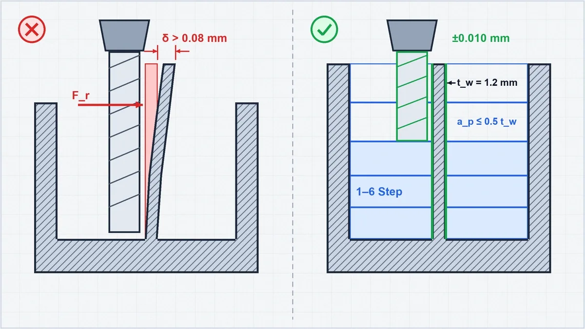
Shop-Floor Alternating 1-to-6 Waterline Step-Down Protocol (Figure 2 Analysis)
In our in-house CNC machining facility practice, when milling 7075-T7351 wing ribs with web thicknesses down to 0.8–1.2 mm (0.031″–0.047″) and height-to-thickness ratios above 25:1, we replace full-depth radial profiling with a staggered 1-to-6 waterline step-down sequence to hold ±0.010 mm (±0.0004″) wall thickness:
- Leave Sacrificial Buttress Stock During Pocket Roughing: High-speed adaptive roughing leaves a stepped pyramidal allowance (0.40 mm / 0.016″ per side at the rib crest increasing to 0.80 mm / 0.031″ toward the pocket root) so the thin web remains rigidly anchored to the uncut lower bulk material.
- Execute Alternating Left-Right Axial Step-Downs (Passes 1 → 6): As shown on the right side of Figure 2, a sharp, polished 3-flute solid carbide end mill (45° helix, high positive rake) finishes Zone 1 on the left face, steps across the rib crest to finish Zone 2 on the right face, and alternates downward through Zones 3, 4, 5, and 6.
- Restrict Axial Finishing Depth to ap ≤ 0.5 · tw: For a 1.2 mm (0.047″) thick aviation rib, each axial finishing step-down is capped at ap = 0.50–0.60 mm (0.020″–0.024″) with a light radial engagement of ae = 0.15–0.20 mm (0.006″–0.008″) at Vc = 320 m/min (1,050 SFM) and fz = 0.06 mm/tooth, ensuring the cutting zone is always directly supported by full-width unmachined stock immediately below the tool tip.
- Support Thin Floor Webs via Vacuum Grid or Low-Melt Alloy Backing: Before machining the opposing side of a 1.0 mm (0.039″) thin floor web, the completed Op10 pockets are seated onto a custom O-ring vacuum chuck or filled with water-soluble/low-melt dampening compound to eliminate “oil-canning” floor drum vibration.
3. Simultaneous 5-Axis Propulsion Prototyping: Ti-6Al-4V Blisks and 17-4PH Stator Rings
Simultaneous 5-axis propulsion prototyping coordinates X, Y, Z linear translation with A/B or B/C trunnion rotation to machine undercut aerodynamic airfoils and stator rings in one setup, holding blade profiles of ⌒ 0.015 mm (0.0006″) and concentricity within ◎ 0.010 mm (0.0004″). Single-setup kinematics eliminate fixture datum shifts, though titanium requires strict heat extraction.
While planar ribs belong on 3/4-axis VMCs, aircraft propulsion, Auxiliary Power Unit (APU), and Environmental Control System (ECS) turbomachinery parts feature twisted blades with deep overhang undercuts. Multi-setup 3-axis indexing leaves blend steps and rotor unbalance (as seen in the simultaneous 5-axis Ti-6Al-4V blisk and 17-4PH turbine stator ring below).
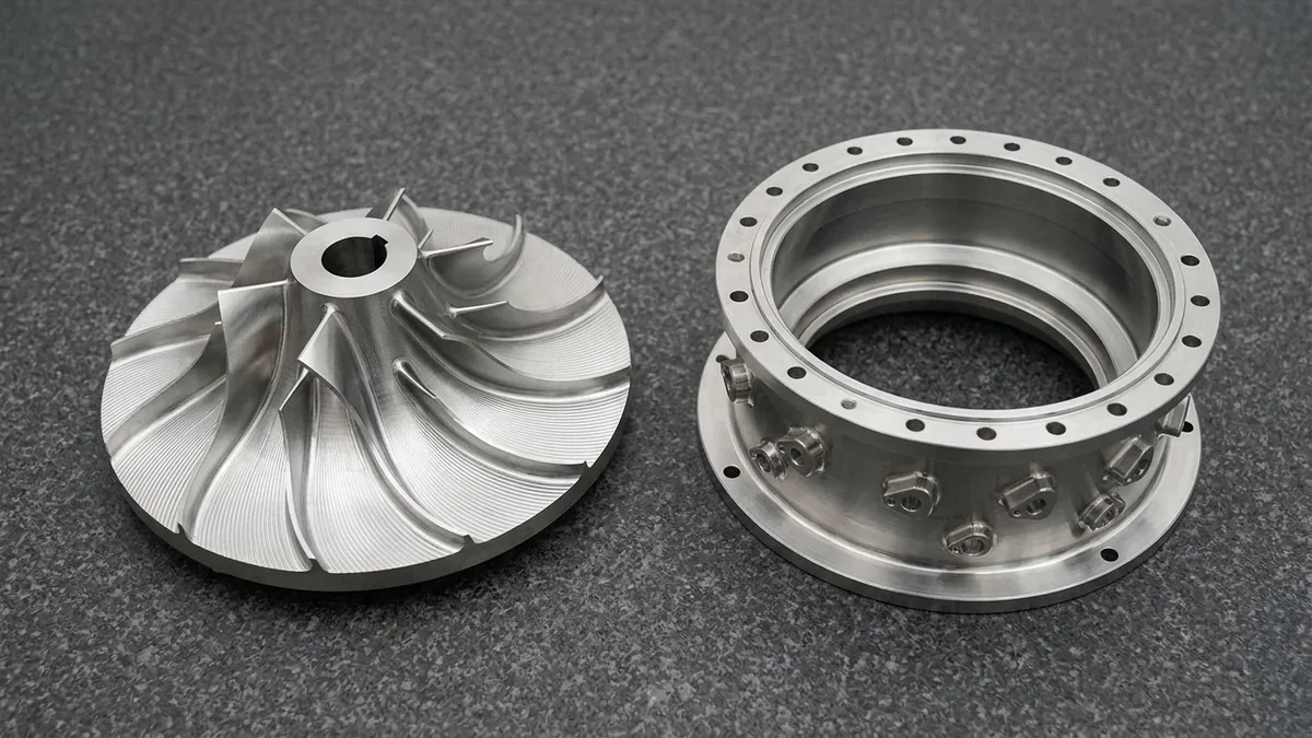
Anatomical Breakdown & 5-Axis Toolpath Architecture in Figure 3
Each turbomachinery prototype in Figure 3 addresses a distinct aerodynamic and thermo-mechanical operating envelope inside an aircraft gas turbine or environmental compressor:
- Ti-6Al-4V Grade 5 (AMS 4928) Centrifugal Compressor Impeller Blisk (Figure 3, Left): Machined from a single forged and ultrasonic-inspected titanium billet, this Blade-Integrated Disk (“blisk”) eliminates mechanical dovetail blade slots, reducing rotor hub mass by up to 30% and eradicating dovetail fretting fatigue at rotational speeds of 45,000 to 80,000 RPM. Its functional geometry comprises full-length twisted inducer blades that draw axial airflow into the rotor, alternating with shortened mid-channel splitter blades that prevent boundary-layer flow separation as gas compresses radially outward. Variable-radius tangential root fillets (R 2.5–4.0 mm) blend each blade smoothly into the contoured hub disk to dissipate centrifugal hoop stress, while the precision central shaft bore (Ø20 mm H6, +0 / +0.013 mm or +0 / +0.0005″) and back-face balancing land ensure Total Indicator Reading (TIR) radial runout stays below 0.010 mm (0.0004″). For deeper rotor-dynamics and channel slotting sequences, see our 5-axis impeller CNC machining guide.
- 17-4PH Stainless Steel (AMS 5643, H900/H1025) Turbine Stator Casing Ring (Figure 3, Right): Encircling the rotating compressor or turbine stage, this containment ring maintains a uniform radial blade-tip clearance (typically 0.15–0.30 mm / 0.006″–0.012″) across thermal transients up to 315 °C (600 °F). Precipitation-hardened 17-4PH provides a low coefficient of thermal expansion (10.8 × 10⁻⁶ /K—less than half that of aluminum) alongside 1,170–1,310 MPa (170–190 ksi) tensile strength. The ring features CNC-turned concentric rabbet pilot flanges (roundness ○ 0.010 mm), 4-axis/5-axis milled peripheral weight-reduction pockets, and compound-angle external bosses bored and thread-milled for Exhaust Gas Temperature (EGT) thermocouples, Pitot-static pressure transducers, and borescope inspection plugs.
Because Ti-6Al-4V has low thermal conductivity (6.7 W/m·K), nearly 80% of cutting heat concentrates at the tool tip. Our 5-axis centers deploy 70-bar (1,015 psi) Through-Spindle Coolant (TSC) with AlTiN variable-helix carbide cutters in climb milling mode (Vc = 55–75 m/min, fz = 0.05–0.08 mm/tooth) to prevent work-hardening and alpha-case embrittlement.
4. Flight-Control Hydraulics & Avionics Cooling: 15-5PH Manifolds, 440C Spools, and 6061 Cold Plates
Flight-control hydraulic actuation and avionics thermal management hardware require multi-process manufacturing chains combining 5-axis compound port drilling, precision bore honing, post-hardening cylindrical grinding to ±0.005 mm (±0.0002″), and conductive surface conversion. Isolating each sub-component to its optimal machine platform guarantees leak-free 35 MPa (5,000 psi) fluid metering and low-resistance heat dissipation.
Fly-by-wire electro-hydraulic servo actuators (EHSAs) demand micron-matched valve assemblies alongside high-density avionics cold plates. As shown in the passivated 15-5PH hydraulic manifold block, cylindrical-ground 440C multi-land servo spool, and open-ended 6061-T651 heatsink cold plate below, each subsystem relies on specialized metallurgy and finishing.
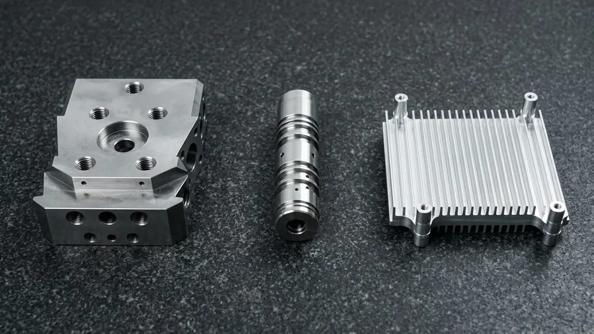
Component-by-Component Engineering & Finishing Breakdown (Figure 4)
- 15-5PH Stainless Steel (AMS 5659, H1025) Flight-Control Hydraulic Manifold Block (Figure 4, Left): Operating under 21 to 35 MPa (3,000 to 5,000 psi) aviation hydraulic pressure (MIL-PRF-83282 or Skydrol), manifold blocks cannot use free-machining 303 or standard 304 stainless steel, nor should they use 17-4PH when high-pressure cross-drilled galleries intersect transverse to the billet rolling direction. Vacuum-remelted 15-5PH eliminates delta-ferrite stringers, delivering uniform short-transverse ductility against fatigue cracking at internal drill intersections. After 5-axis compound-angle port drilling and SAE O-ring boss thread milling, internal cross-port intersections undergo mechanical and high-pressure abrasive deburring, the central spool bore is precision honed to cylindricity ⌭ 0.004 mm (0.00016″) and surface roughness Ra 0.2 µm (8 µin), and the entire block receives ASTM A967 citric/nitric acid passivation (~0.002 µm film thickness, causing zero dimensional shift on honed bores).
- 440C Martensitic Stainless Steel (58–60 HRC) Multi-Land Servo Valve Spool (Figure 4, Center): Sliding directly inside the manifold sleeve without elastomer seals, a servo valve spool meters high-pressure fluid via micron-scale radial diametral clearance (typically 0.004–0.008 mm / 0.00016″–0.0003″) to prevent both internal pressure leakage and spool seizure. We rough-turn the multi-land profile from annealed 440C bar stock, perform vacuum hardening (1,040 °C oil/gas quench) followed by −80 °C cryogenic stabilization (transforming retained austenite so the spool never grows dimensionally in service), and finish the metering lands and journal diameters via precision cylindrical grinding to ±0.005 mm (±0.0002″), concentricity ◎ 0.003 mm, and Ra 0.15–0.20 µm (6–8 µin). Metering land edges are held sharp (edge radius ≤ 0.015 mm, zero feather burrs) to guarantee linear hydraulic flow gain.
- 6061-T651 Conduction-Cooled Avionics Heatsink Cold Plate (Figure 4, Right): Avionics power converters, radar transmit/receive modules, and flight-control FPGAs rely on 6061-T651 aluminum for its high thermal conductivity (167 W/m·K vs 130 W/m·K for 7075-T6). Machined on high-speed 3-axis VMCs, this chassis integrates an open-ended parallel fin array (1.2 mm fin thickness, 2.5 mm channel pitch) for unimpeded ram-air cooling, paired with raised internal PCB mounting bosses fly-cut to a flatness of ⏥ 0.020 mm (0.0008″) to minimize thermal interface resistance. Rather than insulating anodic coatings, avionics cold plates typically specify MIL-DTL-5541 Type II (RoHS-compliant trivalent chromate conversion / SurTec 650) to preserve electrical contact resistance below 5,000 µΩ/in² for Electromagnetic Interference (EMI) chassis grounding, or selective masking where exterior fins receive black MIL-A-8625 Type II anodizing (for oxide growth and masking rules, see our aluminum anodizing specification guide).
| Aviation Material Grade | Finishing Surface Speed Vc (m/min / SFM) | Feed per Tooth fz (mm/tooth / IPT) | Finishing Engagement (ae / ap) | Tool Geometry & Coolant Delivery | Recommended Application / When to Choose |
|---|---|---|---|---|---|
| 7075-T7351 Aluminum | 280–420 m/min (920–1,380 SFM) | 0.06–0.12 mm (0.0024″–0.0047″) | ae = 0.15–0.25 mm; ap ≤ 0.5 · tw | 3-flute polished carbide / ZrN, 45° helix; high-flow flood emulsion | Best for thin-wall 1.2 mm wing rib truss struts and contoured fuselage frames (Ra 0.8 µm) |
| 6061-T651 Aluminum | 350–500 m/min (1,150–1,640 SFM) | 0.08–0.15 mm (0.0031″–0.0059″) | ae = 0.20–0.40 mm; ap = 0.5–1.5 × D | 2/3-flute polished uncoated or DLC carbide; air-blast + flood coolant | Best for high-aspect-ratio avionics heatsink fins and EMI-shielded instrument housings |
| Ti-6Al-4V Grade 5 | 55–75 m/min (180–245 SFM) | 0.05–0.08 mm (0.0020″–0.0031″) | ae = 0.08–0.12 × D; ap = 1.0–1.5 × D | 5/6-flute variable-pitch AlTiN carbide; 70-bar (1,015 psi) TSC mandatory | Best for 5-axis centrifugal compressor blisks and high-load engine mount clevises (Ra 0.4 µm) |
| 15-5PH / 17-4PH (H1025) | 90–130 m/min (295–425 SFM) | 0.05–0.09 mm (0.0020″–0.0035″) | ae = 0.10–0.15 × D; ap = 0.8–1.2 × D | 4-flute TiAlN/AlCrN carbide + carbide parabolic drills with 70-bar TSC | Best for 35 MPa hydraulic valve manifolds and turbine stator casing shroud rings |
| 440C Stainless (58–60 HRC) | 110–150 m/min (turn) / 30 m/s (grind) | 0.08–0.15 mm/rev (turn) / 0.002 mm infeed | 0.15 mm radial grind stock per side post-HT | Vitrified white Al2O3 / CBN cylindrical grinding wheel + chilled flood oil | Best for precision multi-land hydraulic servo spools holding ±0.005 mm (±0.0002″) and Ra 0.2 µm |
5. Quantitative Derivation: 5-Axis Blade Scallop Cusp Height and Barrel-Cutter Stepover Math
Five-axis airfoil blade finishing is governed by differential-geometry coupling between cutter profile radius (Rt or Rb), convex blade curvature radius (ρ), and radial stepover (ae), which dictates residual scallop cusp height (hs). Switching from a ball-nose cutter to a tapered barrel cutter enlarges effective contact radius (Reff) by 11.7×, slashing finishing time.
On compressor blisks, machining cusps taller than 1.5 µm (59 µin) trip laminar boundary layers into turbulence and initiate high-cycle fatigue cracks. As shown in the 2D CAD schematic below, an Rt = 2.0 mm ball-nose cutter requires a 0.15 mm stepover on a ρ = 40 mm blade, whereas a barrel cutter reaches ae = 0.52 mm.
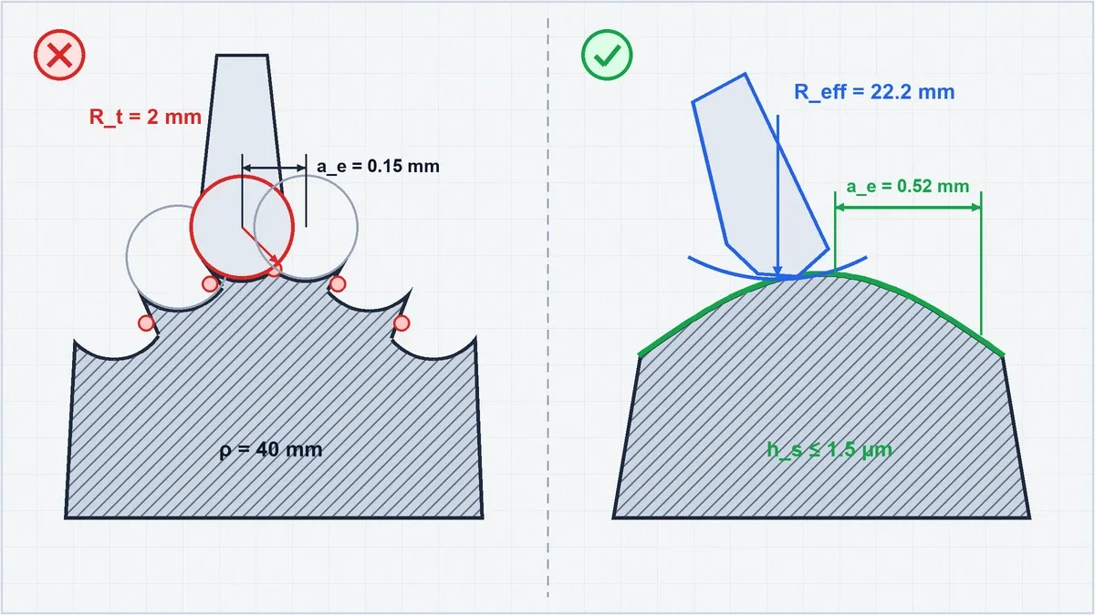
Shop-Floor Mathematical Derivation: Convex Airfoil Scallop Cusp Height & Stepover Optimization
1. Workpiece & Tooling Input Parameters (Illustrative Ti-6Al-4V Blisk Blade Flank):
• Convex airfoil suction-side local curvature radius: ρ = 40.0 mm (1.575″)
• Active aerodynamic blade span width to finish: B = 36.0 mm (1.417″)
• Maximum allowable pre-polish scallop cusp height: hs,max = 0.0015 mm (1.5 µm / 59 µin)
• Tool Option A (Standard Solid Carbide Ball-Nose End Mill): tip radius Rt = 2.0 mm (Ø4.0 mm cutter)
• Tool Option B (Circle-Segment Tapered Barrel Cutter): tangential barrel arc radius Rb = 50.0 mm (1.969″)
2. Governing Kinematic Equations (Convex Curvature Coupling):
When a cutter of profile radius Rtool machines a convex surface of radius ρ, the relative curvature adds, reducing the effective contact radius Reff:
1 / Reff = (1 / Rtool) + (1 / ρ) ⇒ Reff = (Rtool × ρ) / (Rtool + ρ)
The residual scallop cusp height hs across stepover pitch ae and the required pass count Npasses over span B are:
hs = ae² / (8 × Reff) ⇒ ae,max = √(8 × Reff × hs,max) , Npasses = B / ae
3. Step-by-Step Numerical Calculation:
• Option A (Rt = 2.0 mm Ball-Nose End Mill):
Reff,ball = (2.0 × 40.0) / (2.0 + 40.0) = 80.0 / 42.0 = 1.905 mm
ae,ball = √(8 × 1.905 × 0.0015) = √(0.02286) = 0.151 mm → Programmed ae = 0.15 mm (0.0059")
Actual hs,ball = (0.15)² / (8 × 1.905) = 0.0225 / 15.24 = 0.00148 mm (1.48 µm ≤ 1.5 µm)
Nball = 36.0 mm / 0.15 mm = 240 finishing passes per blade flank
• Option B (Rb = 50.0 mm Tapered Barrel Cutter):
Reff,barrel = (50.0 × 40.0) / (50.0 + 40.0) = 2,000.0 / 90.0 = 22.222 mm (≈ 22.2 mm)
ae,barrel = √(8 × 22.222 × 0.0015) = √(0.26667) = 0.5164 mm (≈ 0.52 mm nominal / 0.51 mm conservative CAM input)
Nbarrel = 36.0 mm / 0.5164 mm = 69.7 → 70 finishing passes per blade flank
4. Shop-Floor Engineering Verdict & Process Countermeasure:
Deploying a Rb = 50.0 mm circle-segment barrel cutter expands the effective contact radius from 1.905 mm to 22.22 mm (11.67× gain), widening the allowable stepover from 0.15 mm to 0.51–0.52 mm (3.43× wider pitch) and cutting finishing passes from 240 down to 70 passes per flank (−70.8% toolpath distance). In Ti-6Al-4V blisks, this 70.8% reduction in cutter contact time prevents flank notch wear (holding VB ≤ 0.12 mm across all blades) while maintaining a uniform 1.5 µm surface ready for final Ra 0.2 µm vibratory finishing.
6. Aviation Metrology, Datum-Locking Verification & Shop-Floor Failure Troubleshooting
Aviation metrology verifies ASME Y14.5 GD&T compliance through climate-controlled (20 °C ± 1 °C / 68 °F ± 1.8 °F) Zeiss bridge Coordinate Measuring Machine (CMM) probing, ISO 4287 contact profilometry, and pressure-decay testing with ±0.002 mm (±0.00008″) repeatability. Without strict datum-locking and thermal soak before probing, micron-level aluminum or titanium inspection records suffer thermal drift.
Before any aviation prototype enters our metrology laboratory, it undergoes ultrasonic deionized-water cleaning to strip residual cutting oil and microscopic swarf from deep threads and hydraulic ports, followed by a minimum 4-hour thermal soak on the granite surface plate (as shown in the bridge CMM ruby-probe verification of the 7075-T7351 hydraulic manifold bracket below).
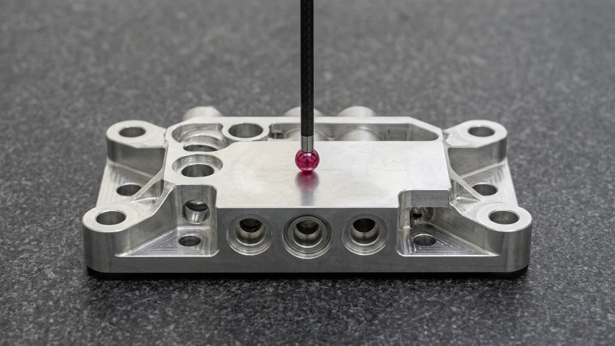
Metrology Datum Establishment & Verification Workflow (Figure 6 Analysis)
In our in-house inspection lab practice, when verifying a multi-datum 7075-T7351 hydraulic actuator manifold bracket like the component in Figure 6, we execute a three-plane kinematic alignment before evaluating internal fluid bores and mounting patterns (for detailed probing physics and sampling density rules, consult our CMM precision metrology and GD&T verification guide):
- Lock Primary Datum A (Top Horizontal Mounting Plane): As captured in Figure 6, the vertical Zeiss bridge CMM head drives a calibrated spherical synthetic-ruby stylus across distributed points on the top machined reference face to verify flatness within ⏥ 0.010 mm (0.0004″) and establish the primary Z-axis spatial plane.
- Establish Secondary Datum B & Tertiary Datum C (Actuator Bore & Dowel Axis): Multi-level circular scanning paths inside the central hydraulic piston bore establish the secondary axis (verifying perpendicularity ⊥ 0.012 mm to Datum A and cylindricity ⌭ 0.006 mm), while probing the precision reamed dowel pin hole locks rotational orientation for true-position (⌖ Ø0.015 mm) evaluation of all surrounding manifold ports.
- Execute Complementary Surface, Optical & Pressure-Decay Verification: Sealing lands and spool bores are checked with ISO 4287 / ASME B46.1 contact profilometers (Ra / Rz), delicate thin-wall sheet brackets are inspected non-destructively on our 2.5D Optical Vision Measuring System (VMS), and internal hydraulic galleries undergo 3.5–6.0 bar (50.8–87.0 psi) dry-air pressure-decay and underwater bubble leak testing alongside full First Article Inspection (FAI) and Mill Test Report (MTR) documentation.
Shop-Floor Aviation Failure Root Cause & Troubleshooting
During rapid prototyping of complex flight hardware, three recurring failure modes must be preempted at the CAM programming and tooling stage:
- Failure Mode 1 — Thin-Wall 7075-T7351 Wing Rib Wall Taper & Crown Bulging: Symptom: A 1.2 mm (0.047″) deep pocket rib measures 1.26 mm at the top crest and 1.19 mm near the floor with visible harmonic chatter ripples (Ra > 3.2 µm). Root Cause: Full-depth radial wall finishing on one side pushed the unsupported elastic cantilever away from the cutter, reducing actual radial depth of cut near the top edge. Corrective Action: Switch to the alternating 1-to-6 waterline step-down sequence (Figure 2) with axial step ap ≤ 0.5 · tw (0.6 mm) and a high-rake polished 3-flute carbide tool so uncut lower stock supports every pass.
- Failure Mode 2 — Ti-6Al-4V Blisk Blade Tip Micro-Chipping & Subsurface Work-Hardening: Symptom: Premature carbide flank notch wear (VB > 0.25 mm) mid-pass leaves glazed, work-hardened streaks and +0.035 mm profile deflection on thin titanium splitter blades. Root Cause: Insufficient coolant pressure allowed a vapor blanket to insulate the cutting zone, while tool dwell at blade leading/trailing edges rubbed the material instead of shearing a clean chip. Corrective Action: Engage 70-bar (1,015 psi) Through-Spindle Coolant (TSC), maintain continuous 5-axis rotary lead/tilt vectors with fz ≥ 0.05 mm/tooth (never dwelling), and replace ball-nose tools with circle-segment barrel cutters (Figure 5) to cut contact distance by 70.8%.
- Failure Mode 3 — 15-5PH / 440C Hydraulic Servo Spool Micro-Stiction & Port Feather Burrs: Symptom: A precision-ground 440C valve spool binds intermittently inside a 15-5PH manifold bore under pressure cycling, or sheds metallic particles into fluid ports. Root Cause: Cross-drilled internal hydraulic port intersections retained microscopic secondary roll-over burrs, or retained austenite in the 440C spool transformed and swelled after grinding. Corrective Action: Incorporate a −80 °C cryogenic soak between vacuum quench and double tempering prior to cylindrical grinding of the 440C spool, and execute automated cross-hole brush/thermal deburring followed by plateau honing (Ra 0.2 µm) on the 15-5PH sleeve bore.
7. Engineering Verdict: Selecting the Optimal Aviation Prototyping Architecture
Selecting the optimal aviation CNC prototyping route requires matching your component’s structural load path, operating temperature, and mating tolerance tier to the most economical machine platform, avoiding unnecessary 5-axis machine-hour surcharges on prismatic parts while guaranteeing single-setup accuracy on complex aerodynamic contours.
- For Primary Airframe Ribs, Bulkheads & Structural Brackets (Stiffness-to-Weight Priority): Specify pre-stretched, over-aged 7075-T7351 (AMS 4045) machined on high-speed 3-axis and 4-axis VMCs using alternating waterline step-down toolpaths and MIL-A-8625 Type II/III anodizing (with silicone plug masking on H7 bearing bores). Ex-factory turnaround is 4 ~ 8 Business Days bare metal or 7 ~ 12 Business Days anodized.
- For High-RPM Impeller Blisks, Inducers & Aero-Engine Contours (Thermal & Airfoil Priority): Specify forged Ti-6Al-4V Grade 5 (AMS 4928) or precipitation-hardened 17-4PH H900 (AMS 5643) routed to simultaneous 5-axis CNC milling centers with circle-segment barrel cutters and 70-bar TSC. Typical ex-factory turnaround is 7 ~ 15 Business Days depending on blade count and CMM airfoil scanning density.
- For 35 MPa Flight-Control Hydraulic Manifolds & Servo Spools (Micron Sealing Priority): Pair 5-axis drilled, plateau-honed, and ASTM A967 passivated 15-5PH H1025 manifold blocks with vacuum-hardened, cryogenically stabilized, and cylindrical-ground 440C (58–60 HRC) spools holding ±0.005 mm (±0.0002″) land tolerances.
- For Avionics Cold Plates, Sensor Enclosures & Fast Iteration Prototypes (Thermal & Schedule Priority): Choose 6061-T651 (AMS 4027) milled on 3-axis VMCs with MIL-DTL-5541 Type II (SurTec 650 / Alodine) conductive chromate conversion for EMI grounding and low thermal contact resistance.
- Preventing Residual Stress Warping & Thermal Drift in Aluminum CNC Milling
- Sharp Internal Corners in CNC Machining: End-Mill Cantilever Deflection (L³/D⁴) & Relief DFM
- Simultaneous 5-Axis CNC Machining & CAM Engineering Practice for Impellers
- Aluminum Anodizing Specification Guide: MIL-A-8625 Type II vs. Type III Hardcoat & Masking
- Zeiss CMM Precision Metrology, Datum Alignment & First Article Inspection (FAI) Guide
- Aerospace Sheet Metal Fabrication: 5052/6061/7075 Forming Radii & DFM Standards
8. Technical Engineering FAQ
Over-aged 7075-T7351 aluminum (AMS 4045) trades 10% of peak T651 yield strength for superior Stress Corrosion Cracking (SCC) resistance across exposed short-transverse billet cores. Our machine shop pairs 7075-T7351 with alternating step-down milling to hold ±0.010 mm (±0.0004″) tolerances on thin airframe ribs.
Planar wing ribs, mounting brackets, and conduction-cooled 6061-T651 avionics cold plates should be routed to high-speed 3-axis and 4-axis Vertical Machining Centers (VMCs) using custom soft jaws. Simultaneous 5-axis milling is reserved for undercut Ti-6Al-4V impeller blisks, compound-angle hydraulic manifolds, and contoured fuselage frames.
Martensitic 440C stainless steel spools are rough-turned, vacuum heat-treated to 58–60 HRC with cryogenic stabilization, and finished via precision outer-diameter cylindrical grinding to ±0.005 mm (±0.0002″). The mating 15-5PH manifold bore undergoes precision honing to Ra 0.2 µm (8 µin) and ASTM A967 passivation without dimensional change.
Bare-metal aviation CNC prototypes ship ex-factory in 4–8 business days (7–12 business days with MIL-A-8625 anodizing or ASTM A967 passivation), plus 3–5 days air transit. Quality deliverables include traceable Mill Test Reports (MTR), 20 °C Zeiss CMM coordinate records, and First Article Inspection (FAI) reports.
Ready to Machine Your Custom Aviation CNC Prototypes?
Upload your 3D CAD models (STEP/IGES) and 2D GD&T tolerance drawings for a comprehensive manufacturability review, datum-locking strategy, and custom production quotation from our in-house engineering team.
Upload 3D CAD for Engineering DFM & RFQ →