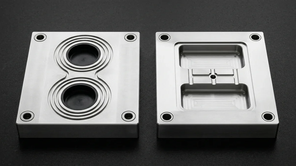
Selecting the proper polymer forming technology dictates tooling capital expenditure, unit cost, and component durability. Therefore, manufacturing engineers frequently compare compression molding vs injection molding when developing elastomeric or structural plastic parts. Both processes utilize precision heated metal tooling to shape raw polymer materials. However, their fundamental heating mechanics, tooling configurations, and resin compatibilities differ substantially.
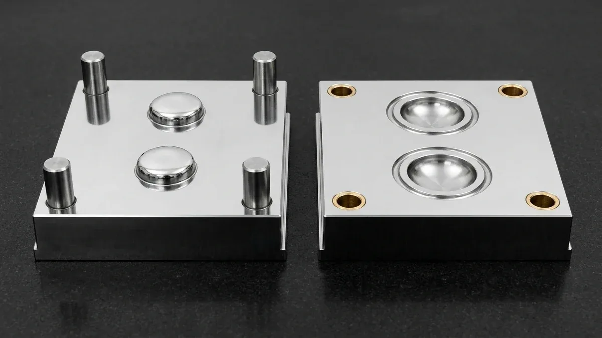
Compression molding relies on placing a preheated polymer charge directly into an open mold cavity. Subsequently, hydraulic pressure closes the heated tool halves, forcing viscous material into every corner. Conversely, injection molding feeds granular resin through a heated reciprocating screw barrel. The screw injects molten resin at high velocity into a clamped, closed mold cavity. In this engineering evaluation, we examine critical technical distinctions to guide your manufacturing program.
1. Fundamental Process Kinematics and Cycle Dynamics
The mechanical workflow of compression molding begins with precise manual or robotic charge placement. Because the cavity remains open initially, material flows under direct vertical platen compressive force. Furthermore, excess resin escapes into perimeter flash grooves, requiring secondary deflashing operations. In shop-floor practice, compression molding cycles range from one to several minutes to allow thorough material cross-linking.
In contrast, high-speed injection molding delivers rapid, fully automated production cycles. Molten polymer enters through cold or hot runner manifolds under thousands of pounds of hydraulic pressure. Furthermore, water cooling channels within the tool extract thermal energy within seconds. Therefore, injection cycle times typically range between fifteen and sixty seconds per shot.
2. Material Compatibility: Thermosets, Elastomers, and Thermoplastics
Material science represents a major boundary separating these two molding disciplines. Compression molding excels at processing high-viscosity thermosetting resins, synthetic rubbers, and fiber-reinforced compounds. Common materials include silicone rubber, EPDM, fluorosilicone, and sheet molding compounds. Because thermoset polymers form irreversible chemical cross-links when heated, they cannot be melted again after curing.
Conversely, injection molding processes engineering thermoplastics such as ABS, polycarbonate, nylon, and PEEK. Through our advanced custom injection molding services, tooling teams control thermal shrinkage and crystalline warpage. In addition, low-volume elastomeric prototypes can be produced via polyurethane vacuum casting before investing in hardened production steel. Thus, material thermal properties determine whether compression or injection tooling proves most suitable.
The comparative engineering parameters of both manufacturing methods are detailed in the table below.
| Engineering Attribute | Compression Molding | High-Pressure Injection Molding |
|---|---|---|
| Primary Material Class | Thermosets, Silicone, EPDM, SMC | Thermoplastics, TPE, Liquid Silicone |
| Typical Cycle Time | 1 to 10 minutes per cycle | 15 to 60 seconds per cycle |
| Tooling Initial Cost | Moderate (Simplified Compression Mold) | High (Precision Multi-Action Injection Mold) |
| Geometric Complexity | Low to medium, flat cross-sections | Extremely high, thin walls, internal ribs |
| Scrap and Flash Generation | High flash volume requiring trimming | Minimal flash, recyclable runners |
3. Tooling Complexity, Part Geometry, and Deflashing Operations
Tooling design requirements differ drastically between the two forming methods. Compression molds feature relatively straightforward cavities without complex runner manifolds or narrow sprue gates. Consequently, compression tooling costs remain significantly lower, making it attractive for low-to-medium volume production. However, compression parts cannot easily incorporate deep internal undercuts, delicate side-action slides, or extremely thin rib walls.
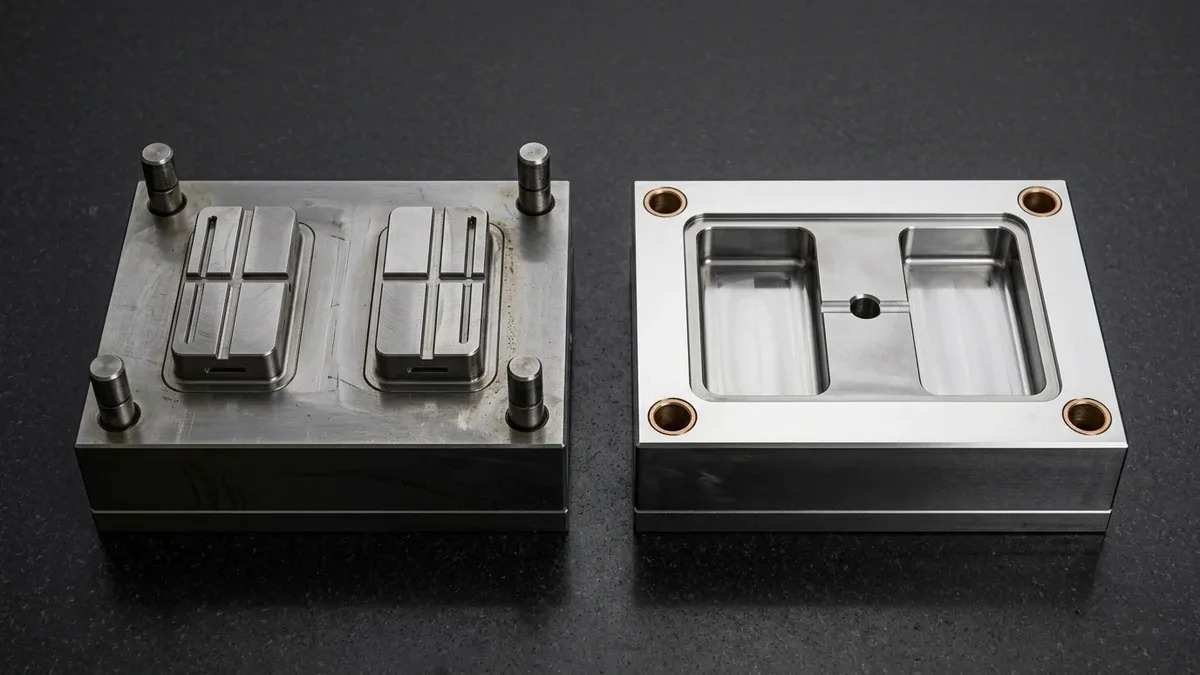
Conversely, injection molds incorporate multi-plate assemblies, precision lifters, and hydraulic side cores. Therefore, injection tooling easily handles complex geometric housings, threaded bosses, and snap-fit features. Furthermore, parts eject clean and virtually flash-free, eliminating labor-intensive secondary trimming. Moreover, automated robotic pickers can transfer components directly into packaging cells.
4. Cost Economics and Volume Breakeven Analysis
Selecting between compression and injection molding involves a direct tradeoff between tooling investment and piece-part labor cost. For production runs below 5,000 large rubber gaskets, compression molding provides superior cost efficiency. The lower initial tooling expense offsets longer molding cycle times and manual deflashing labor. Therefore, compression molding dominates heavy-duty industrial seals, vibration mounts, and thick composite panels.
However, when part volumes exceed 10,000 units, injection molding delivers unmatched economic scaling. Fast cycle times and automated part ejection reduce per-part labor overhead to a minimal fraction of total unit cost. In addition, tighter dimensional tolerances reduce quality inspection overhead across massive production runs. AS Prototypes provides thorough DFM consultations to help engineering teams select the most cost-effective tooling pathway.
The operational cost structure and economic volume thresholds are summarized in the table below.
| Cost Factor | Compression Molding Strategy | Injection Molding Strategy |
|---|---|---|
| Tooling Breakeven Volume | 500 to 5,000 parts | 5,000 to 100,000+ parts |
| Secondary Labor Demand | High (flash trimming, cryogenic deflashing) | Very low (automated gate degating) |
| Dimensional Tolerances | ±0.10 mm to ±0.25 mm | ±0.025 mm to ±0.05 mm (ISO 20457) |
| Wall Thickness Range | 1.5 mm to 25.0+ mm | 0.5 mm to 4.5 mm uniform walls |
| Ideal Product Families | O-rings, brake pads, electrical insulators | Enclosures, medical devices, automotive gears |
5. Technical Engineering FAQ
Compression molding is ideal for producing large, thick-walled elastomeric components, silicone seals, and heavy thermoset composite parts in low-to-medium volumes (500 to 5,000 units). It offers significantly lower initial tooling investment, avoids gate vestige marks, and excels with high-viscosity rubber compounds and sheet molding compounds (SMC).
Injection molding injects liquid polymer into a rigidly clamped, closed mold cavity under closed-loop hydraulic pressure and packing control. In contrast, compression molding involves open-cavity charge positioning and vertical platen closure, causing slight flash thickness variations along horizontal parting lines.
While feasible for specialized ultra-high-molecular-weight polyethylene (UHMWPE) or PTFE billets and long-fiber thermoplastic composites, compression molding standard thermoplastics is generally inefficient because the entire steel mold must be heated above the polymer melting point and cooled below its solidification temperature on every single cycle. High-pressure injection molding into a temperature-stabilized tool is far more productive for thermoplastic components.
Transition Seamlessly from Rapid Tooling to High-Precision Molding
Optimize cavity life, gate geometry, and part unit economics with our in-house tooling and injection molding engineering team. Upload your 3D CAD models (STEP/IGES) for a comprehensive Moldflow and DFM manufacturability assessment.
Upload 3D CAD for Tooling & Molding DFM Review